

PacComm Micropower-2_Tiny-2_Technical_reference_manual_DC7XJ_1989.pdf PacComm_Micropower-2_Tiny-2_Technical_reference_manual_DC7XJ_1989.pdf

TECHNICAL REFERENCE MANUAL
for
PacComm Packet Controller Models
TINY-2 and MICROPOWER-2

TINY-2/MICRO-2 Technical Ref., 2. Ed 1989
TABLE OF CONTENTS
INTRODUCTION ............................................................................... 4
Features ................................................................................ 4
NET/ROM and ROSE Compatibility ........................................... 4
COMPUTER INTERFACING ................................................................. 5
RS-232 Port Signals ................................................................ 5
Nonstandard RS-232C Serial Ports ........................................... 6
Serial Port Operation At TTL Levels .......................................... 7
Serial Data Signal Definitions .................................................. 7
RS-232C Handshaking Protocol ................................................ 9
RADIO INTERFACING ........................................................................ 10
Radio Connector (J2) Pin Definitions ........................................ 10
Direct Connection to Microphone and Speaker .......................... 10
Accessory Jack Connection ...................................................... 11
External Interface Box ............................................................ 11
HARDWARE DESCRIPTION ................................................................ 12
LEDs ..................................................................................... 12
Detailed Circuit Description ..................................................... 12
Modem Disconnect - J5 ........................................................... 13
ADJUSTMENTS ................................................................................. 16
Jumper Functions ................................................................... 16
JP B: Lithium Battery .................................................... 16
JP D: NET/ROM + RFDCD ............................................. 16
JP L: Digital Loopback .................................................. 16
JP RA: Audio Input Impedance ..................................... 16
JPAux: Auxiliary I/O ..................................................... 16
JP 8: Power Connection ................................................ 16
Trimpot/Varicap Adjustments .................................................. 16
Baud Rate Setting .................................................................. 16
Audio Input Level ................................................................... 17
Transmit Level Setting ............................................................. 17
Modem Receive Bias Adjustment ............................................. 18
Carrier Detect Level ................................................................ 18
Crystal Oscillator Adjustment .................................................. 18
TROUBLESHOOTING ......................................................................... 19
Loopback testing .................................................................... 20
Analog loopback .......................................................... 20
Digital loopback ........................................................... 20
General Tests ......................................................................... 20
Step 1: Obvious Problems ............................................. 20
Step 2: Power Supply ................................................... 21
Computer Terminal Interface .................................................. 21
Packet Controller won't sign on to the Computer ............ 21
The Controller prints only gibberish ............................... 21
The Controller won't accept commands ......................... 22
- 2 -

Other Symptoms .................................................................... 22
APPENDICES
Node Interconnection Cables .................................................. 24
Computer Interfacing Diagrams ............................................... 25
Radio Interfacing Diagrams ..................................................... 26
RS-232 Signal Table ................................................................ 27
Bit-Shifted ASCII Character Table ............................................. 28
Schematic .............................................................................. 29
TINY-2/MICRO-2 Technical Ref., 2. Ed 1989
TINY-2/MICRO-2 appears dead ..................................... 22
Modem won't key transmitter ........................................ 22
Uncopyable transmitted packets .................................... 22
Uncopyable received packets ........................................ 23
DCD LED flickers excessively or stays on ........................ 23
Transmitter locks in transmit condition ........................... 23
Dual TINY-2/MICRO-2 Node .......................................... 24
Dual Node, TINY-2/MICRO-2 and TNC-2(00) .................. 24
Triple Node .................................................................. 24
- 3 -

TINY-2/MICRO-2 Technical Ref., 2. Ed 1989
INTRODUCTION
This manual applies to both the TINY-2 and MICROPOWER-2 packet controllers. These units share
the same basic design and interface to radios and computer terminals identically. The term TINY2/MICRO-2 is used throughout this manual to refer to both units when dealing with components
and procedures which are the same for both units.
The terms "Computer and terminal" are used interchangeably to refer to the computer or terminal
used to communicate with the packet controller. This is not meant to imply that a computer is necessary for operation of a packet controller.
Every effort has been made to make this manual complete and accurate, however PacComm assumes no responsibility for damages incurred as a result of using this documentation. PacComm
reserves the right to make changes to equipment specifications or documentation at any time
without notice or obligation to previous purchasers. Your comments and suggestions for improvement are welcome.
Be sure to read any errata, manual updates, and software release notes before operating the packet controller.
Features
Firmware
Completely TNC-2 firmware Compatible
Supports all 'TAPR' commands plus many PacComm additions.
Personal Message System (optional on TINY-2)
Hardware
NMOS Z-80 CPU and SIO (MDLC) [MICROPOWER-2: CMOS]
4.9 MHz CPU clock speed
32k EPROM and 32k RAM
Typical Power Consumption: 9 – 14 VDC @ 220 mA [40 mA]
Crystal controlled IC modem supports 1200/2200 Hz tones
DE-9P (male) for RS-232 Computer
TNC-2 type modem disconnect header
Power, Connect, Status, PTT, Carrier Detect LEDs
Extruded aluminum case 5 × 7 × 1 3/8 inches with gray, oven baked wrinkle finish
Metal end panels grounded to prevent RFI
MICROPOWER-2 printer port and hardware clock options
NET/ROM and ROSE Compatibility
The TINY-2/MICRO-2 are TNC-2 compatible meaning that an EPROM designed for a TNC-2 compatible (such as both NET/ROM and ROSE networking EPROMs) will operate in a TINY-2/MICRO-2.
Please refer to Appendix A for interconnection cable Information for dual/multi-node units.
- 4 -

TINY-2/MICRO-2 Technical Ref., 2. Ed 1989
COMPUTER INTERFACING
The TINY-2/MICRO-2 packet controller communicates with the computer or terminal through a serial port using either RS-232C or "TTL" level signals. One of these signal levels should properly interface to most computers. See the Appendices to this manual for specific computer interfacing instructions.
RS-232 Port Signals
The serial port connectors on the TINY-2/MICRO-2 packet controller are on the rear panel marked
"RS-232" and "TTL Computer". The pins on the serial port connector of packet controller that must
be connected are shown in the following table. This is commonly called a "three-wire" RS-232 cable.
RS-232 Serial Port "3 Wire" Cable Wiring for DB-25
Computer DB-25 TINY-2/MICRO-2
1 and 7 –––––––– 5
2 ––––––––––––– 3
3 ––––––––––––– 2
RS-232 Serial Port "3 Wire" Cable Wiring for DE-9
Computer DE-9 TINY-2/MICRO-2
5 and Shell ––––– 5
2 ––––––––––––– 2
3 ––––––––––––– 3
The packet controller is configured as Data Communications Equipment (DCE), the technical term
for an RS-232C modem. Most computers and terminals are configured as Data Terminal Equipment
(DTE). Specifically, the packet controller connector is an IBM "AT style" using a male DE-9 connector, wired as DCE rather than DTE. If you use an "AT" PC or portable Computer with a 9-pin serial
port, you can wire cable connector pins 2 through 8 directly (pin 2 to pin 2, etc.).
Pin 1 on the TINY-2/MICRO-2 is the Data Carrier Detect (DCD) signal which goes high (true) when
the packet controller is in the "connected" state. This is analogous to the DCD signal on telephone
modems, i.e. the pin is asserted when a communication connection exists. Pin 9 is used as an auxiliary radio carrier detect input. This pin may also be used when two or more packet controllers are
mated for use with network firmware such as the NET/ROM or ROSE EPROM. More detailed information is presented later in the manual.
Some computers require that Clear To Send (CTS) of the computer serial port connector (pin 5 of a
DB-25 or pin 8 of a DE-9) be connected to an appropriate signal. Others may require connections
for Data Carrier Detect (DCD) (pin 8/pin 1) and Data Terminal Ready (DTR) (pin 20/pin 4). You
may jumper the computer's input and output signals on DB-25 pins 4/5 (DE-9 pins 7/8), and on
DB-25 pins 6/8/20 (DE-9 pins 6/1/4) in addition to the connections shown in the "3 wire" RS-232
diagram above, or build an "8 wire" interface cable as shown below:
Jumpering RTS/CTS and DTR/DSR/DCD at the Computer Gable End
DB-25: DE-9:
4 –––––– 5 7 –––––– 8
6 –––––– 8 –––––– 20 1 –––––– 4 –––––– 6
- 5 -

TINY-2/MICRO-2 Technical Ref., 2. Ed 1989
"Eight-wire" RS-232 Cable
Computer DB-25 or DE-9 to TINY-2/MICRO-2 DE-9P
1 –––––––– Shell –––––––– 5
2 ––––––––– 3 –––––––––– 3
3 ––––––––– 2 –––––––––– 2
4 ––––––––– 7 –––––––––– 7
5 ––––––––– 8 –––––––––– 8
6 ––––––––– 6 –––––––––– 6
7 ––––––––– 5 –––––––––– 5
8 ––––––––– 1 –––––––––– 1 "connected" signal
20 –––––––– 4 –––––––––– NC
Non-Standard RS-232C Serial Ports
NOTE: Some computers which require an external TTL to RS-232 adapter to support an RS-232 serial port may be interfaced to the TINY-2/MICRO-2 without the RS-232 adapter unit by using the
TINY- 2/MICRO-2 TTL level signals.
Computers with non-standard RS-232 serial ports must meet the following conditions:
Voltage levels sent by the computer must be greater than +3 Volts in one state and less than
-3 Volts in the other state.
The polarity of the signals must conform to the RS-232C standard, i.e. the low voltage state is
a logical "1" and the high voltage state is a logical "0".
Make or buy a cable that provides the following connections:
The computer serial port common (ground) pin must be tied to the TINY-2/MICRO-2 serial port
connector pin 5.
The signal line that sends data from the computer must be tied to the TINY-2/MICRO-2 connector pin 3.
The pin on which the computer receives data must be tied to the TINY-2/MICRO-2 connector
pin 2.
The documentation provided with the computer or its accessory serial port should clarify any requirements for additional signals.
- 6 -

TINY-2/MICRO-2 Technical Ref., 2. Ed 1989
P3
Signal Name
Description
8
No Connection
Serial Port Operation At TTL Levels
The TINY-2/MICRO-2 packet controller is designed to operate with computers which have a TTL
level serial port without requiring the use of an RS-232C adapter. This includes such popular computers as the Commodore VIC-20, C-64, and C-128. TTL signals are routed through an 8 pin connector on the rear panel. TTL signal levels must be greater than +2.4 Volts in one state and less
than +.4 Volts in the other state.
Use caution in connecting the TTL cable to insure that pin one of the cable is attached to pin one
of the connector. Pin one is clearly marked on the rear panel of the controller. Pin one of the cable
connector is marked with a red stripe, Be sure to observe this marking both in constructing and attaching the cable.
TTL serial port signals used by the TINY-2/M1CRO-2 controller.
1
Receive Data
2
Carrier Detect
3
Frame Ground
4
Clear to send
5
Transmit Data
6
Signal Ground
7
Request to send
Serial data to computer from the TlNY-2/MICRO-2
Goes high when connection exists
Common ground for case and data lines
Computer Signal Clearing Controller to send data
Serial data to the TINY-2/MICRO-2 from computer
Common ground for both data lines and case
Controller signal to computer when data is ready
Serial Data Signal Definitions
This section describes the pins used on the packet controllers serial port connectors. Since the pins
are defined with respect to the Data Terminal Equipment (DTE) (computer) end of the circuit, and
the packet controller is wired as Data Communications Equipment (DCE) (modem), some standard
pin names appear to be the reverse of the packet controller function. A complete RS-232 signal table appears in the Appendices.
Serial Port Pin Functions
Frame Ground (FG) is provided for attachment to the chassis of the packet controller and the
chassis of the attached computer terminal. This is common to the signal ground on the TINY2/MICRO-2.
Transmit Data (TXD) is an input line to the packet controller on which the attached computer
terminal device sends data.
Receive Data (RXD) is an output line from the TINY-2/MICRO-2 on which it sends data to the
attached computer terminal device.
Request to Send (RTS) is an input to the packet controller signaling that the attached computer terminal device is ready to accept data from the TINY-2/MICRO-2. This line is used for hardware flow control.
Clear To Send (CTS) is an output from the packet controller signaling the attached computer
terminal device to send data to the TINY-2/MICRO-2. This line is used for hardware flow control.
Data Set Ready (DSR) is an output from the packet controller telling the attached computer
terminal device that the packet controller is operational. On the TINY-2/MICRO-2 this pin is
tied high (ready).
Signal Ground (SG) is the common, or return, path for all signals between the TINY-2/MICRO-2
and the attached Computer terminal device. It is common with the frame ground.
- 7 -

TINY-2/MICRO-2 Technical Ref., 2. Ed 1989
Definition
Pin
Nr.
Pin
Nr.
Pin
Nr.
Pin
Nr.
9
Data Carrier Detect (DCD) is an output from the packet controller. DCD reflects the status of
the CON LED: It is high when a packet connection exists and it is low when no connection exists. This Signal is useful when the packet controller is used with telephone style and BBS software, since the connect signal, like a modem carrier on the telephone, indicates the presence
of a user.
Data Terminal Ready (DTR) is an input to the TINY-2/MICRO-2 signaling that the attached
computer terminal device is ready to accept data from the packet controller. Not used on the
TINY-2/MICRO-2.
The table below provides a cross reference to the pinouts of the industry standard 25 pin connector as used on many computers and terminals. The TNC-2 and PacComm TNC-200, and relates
them to the newer 9 pin connectors used on many modem computers and the TINY-2/MICRO-2.
Note that connecting a DTE device to a DCE device using either 25 pin connectors or 9 pin connectors at both ends of the cable provides a 'straight through' wiring of pin numbers, i.e. connect column 1 to column 4 OR connect column 2 to column 3. However, when a 25 pin connector and 9
pin connector are used on the same cable, i.e. column 1 to column 3, several pairs of signal lines
must be crossed.
TINY-2/MICROPOWER-2 RS-232 Serial Port Signal Cross Reference
Conventional
RS-232
FG
TXD
RXD
RTS
CTS
DSR
SG
DCD
Test
Test
DTR
RI
a
This line goes high when a connection exists
b
RFDCD (Also used for multi-node NET/ROM and ROSE)
Conventional
RS-232 DTE DB-25
1
2
3
4
5
6
7
8
9
10
20
22
IBM AT
RS-232 DTE DE-9P
shell
3
2
7
8
6
5
1
V+
V-
4
9
TINY/MICRO
RS-232 DCE DE-9P
5
3
2
7
8
6
5
a
1
-
-
nc
b
TNC-2(00)
RS-232 DC DB-25
1
2
3
nc
5
6
7
a
8
+12V
-12V
20
(23)
- 8 -

TINY-2/MICRO-2 Technical Ref., 2. Ed 1989
RS-232C Handshaking Protocol
The CTS and RTS lines of the TINY-2/MICRO-2 serial port (labeled P4 on the circuit board and RS232C on the rear panel) are used by the TINY-2/MICRO-2 firmware for hardware "handshaking" to
control the flow of data between the computer and the packet controller.
The TINY-2/MICRO-2 always asserts (makes true) Data Set Ready (DSR) on P4 pin 6 via a pullup
resistor. Thus, whenever the TINY-2/MICRO-2 is powered up, it signals to the computer connected
to P4 that the packet controller is "on line".
The computer terminal indicates it is ready to receive data from the TINY-2/MICRO-2 by asserting
its Request To Send (RTS) Signal on P4 pin 4. The packet controller will send data when RTS is asserted (if there is data to be sent). If the computer is not ready to receive data, it negates (make
false) RTS to the TINY-2/MICRO-2. Thus, data flow from the packet controller to the computer is
controlled by the use of the RTS line.
The packet controller asserts its Clear To Send (CTS) Output, P4 pin 5, whenever it is ready to receive data from the computer, if the TINY-2/MICRO-2's buffers fill, it will negate CTS, signaling the
computer to stop sending data. The packet controller will assert CTS when it is again ready to receive data from the computer. Thus, data flow from the computer to the packet controller is regulated by the use of the CTS line. The CTS line is always toggled, even if "software flow control" is
enabled in this direction.
If "software flow control" is preferred, or if the computer terminal serial I/O port does not implement CTS/RTS and DTR/DSR handshaking, then a three wire cable should be used. If these RS232 control lines are not connected they will be pulled up (and thus asserted) by resistors at the
TINY-2/MICRO-2 end and proper operation will result. However, a non-standard serial port may
use some pins for other purposes, such as supplying power to a peripheral device, so be sure that
the system either implements the CTS, RTS and DSR handshake or has no connections to these
pins of P4 whatsoever. Note that reference to RS-232C "compatibility" or the presence of a DB-25
type connector does not guarantee that you have a standard RS-232C serial port!
The PacComm TINY-2/MICRO-2 packet controller supports asynchronous computer terminal baud
rates of 300, 1200, 2400, 4800, 9600 and 19,200. The port supports standard parity options as
well as 7- or 8-bit character lengths. Factory settings are 1200 bauds, eight bit wordlength, no parity and one stop bit. (UK = 1200, 7, E, 1)
If you want to interface the TINY-2/MICRO-2 with a device configured as DCE, such as a telephone modem or another packet controller, a so-called "null modem" cable may be constructed to
interchange the data and handshake signals.
- 9 -

TINY-2/MICRO-2 Technical Ref., 2. Ed 1989
RADIO INTERFACING
This section describes how to connect the signal cable between the TINY-2/MICRO-2 and the radio. The interconnection should be planned so as to minimize pickup of stray audio and RF noise
by the lines. You should use shielded wire for all signal-carrying leads.
Read the remainder of this chapter carefully before starting to interface the packet controller to
the radio.
Connect the TINY-2/MICRO-2 and radio according to one of the following methods. Then turn on
the packet controller and computer and start the computer communications program. Connect the
radio to a dummy load and listen to the transmission with another nearby radio. Set the transmit
level by the procedure in the Adjustments Chapter.
You should use shielded wire for all signal-carrying leads. If you notice a significant hum level in
the monitored audio, take measures to remove it. If the transmitter has an adjustable microphone
gain control, try reducing the sensitivity of the transmitter microphone circuit and increasing the
signal level from the TINY-2/MICRO-2 to minimize hum or other noise problems.
Radio Connector (J2) Pin Definitions
Interfacing the TINY-2/MICRO-2 to a radio involves connecting the following signals at J2, the five
pin DIN connector.
Pin 1 - Audio output from the TINY-2/MICRO-2 to the transmitter.
Pin 2 - Ground for both audio and PTT.
Pin 3 - Push-to-talk to allow keying the transmitter.
Pin 4 - Receive audio from the receiver speaker or auxiliary jack to the TINY-2/MICRO-2.
Pin 5 - Optional Radio Squelch input for RF Carrier Detection.
Radio Connector Viewed from Rear of Packet Controller
Direct Connection to Microphone and Speaker
The packet controller was designed to allow hookup and testing to be done without any modifications to the radio or any signal level balancing devices in the cables. The direct interconnection
method is useful if you devote the radio exclusively to packet. If you share the radio between
packet and voice, you may want to use the external interface method below. The packet controller's audio signals are fed directly into the microphone connector or similar auxiliary input of the
radio, and the TINY-2/MICRO-2 output is adjusted to give a proper modulation level. The receiver
audio is taken from an auxiliary audio output or Speaker jack and fed directly to the packet controller.
- 10 -
TINY-2/MICRO-2 Technical Ref., 2. Ed 1989
Accessory Jack Connection
If the radio has an accessory jack with PTT, transmit audio, and receive audio signals, all connections between the radio and TINY-2/MICRO-2 may be done through this jack. The TINY-2/MICRO2 is designed to operate with from 10 to 700 millivolt audio input. This is compatible with the signal level provided by most modern transceivers at the "Fixed Audio Output" connector on the rear
panel. It is recommended that a squelched fixed audio output be used if available. If the audio
output is squelched or can be adjusted to a low enough level to prevent false carrier detection, a
direct connection to the TINY-2/MICRO-2 audio input may be made.
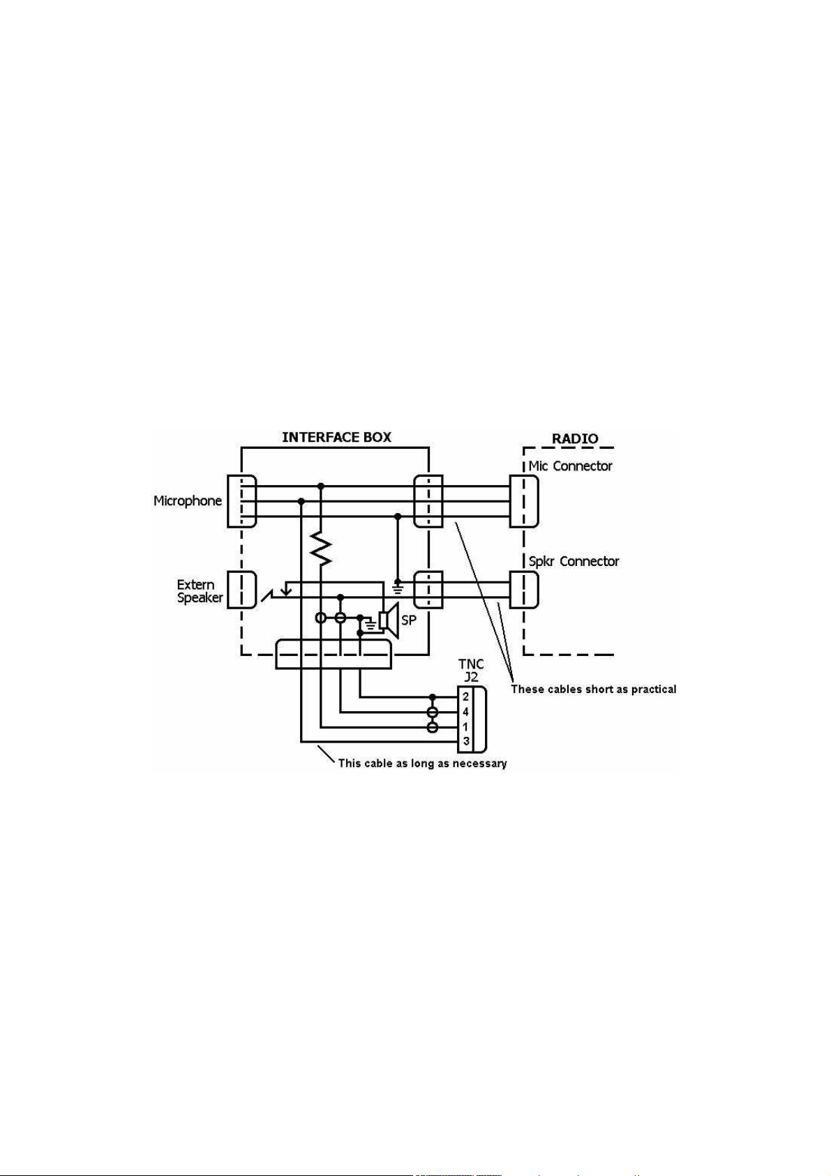
External Interface Box
If you desire to use the radio for both packet and voice, and the radio does not have an accessory
jack and you don't wish to add a connector to the radio, you should construct a separate interface
box to permit simultaneous connection of the TINY-2/MICRO-2 and a microphone. It may either
have its own speaker or pass the signal through to a speaker so that you can monitor the receive
audio while the packet controller is hooked up. A schematic of an external interface box is shown
below.
External Interface Circuit Schematic
- 11 -

TINY-2/MICRO-2 Technical Ref., 2. Ed 1989
HARDWARE DESCRIPTION
This section includes detailed hardware specifications and a functional description of the hardware
design of the TINY-2 and MICROPOWER-2 packet controllers. Specifications apply to both packet
controller models unless specified otherwise. MICROPOWER-2 specifications (when different) will
be placed in square brackets [ ]. Firmware specifications and operating instructions are contained
in the Operating Manual.
LEDs
PWR The POWER LED is illuminated whenever the TINY-2/MICRO-2 is connected to a power
source and the power switch is on.
CON The CONNECT LED illuminates when an AX.25 connection exists on the selected stream for
that port. (See multi-connection explanation in Operating Manual).
STA The STATUS LED illuminates whenever an AX.25 frame has been sent but not yet acknowl-
edged. If a connection is to be terminated (DISCONNECTED) and the STA LED is lit, some
frames which were sent but not acknowledged may be lost.
PTT The PTT LED illuminates whenever the TINY-2/MICRO-2 activates the radio keying line.
DCD The DCD LED illuminates when the modem senses a signal.
Detailed Circuit Description
Oscillator: The crystal, capacitors and resistors in the 74HC4060 (U7) circuit provide for a stable clock source for the 4.9152 MHz master clock. The 74HC4060 also provides all baud clocks
(X16) and a 600 Hz signal for the real time clock interrupt applied to the SIO (U14) SYNC-B input.
CPU Complex: The microprocessor (U1) is an NMOS Z-80 (8400-06) [CMOS, 84C00-06]. Both
asynchronous serial and HDLC functions are performed by a Z80 SIO/0 (8440-06) [84C40-06]
(U14). The 27256 [27C256] EPROM (32k bytes) (U2) contains all the firmware, addressed from
0 to 7FFF. The 32k × 8 RAM (U8) holds all buffered data and battery backed parameters for
the 8400-06 [84C00-06](Z-80) CPU (U1). RAM is addressed from 8000 to FFFF. Each memory
device's chip select is provided by the 74HC139 decoder (U3), and the RAM chip select is also
buffered by a power failure detection circuit. When voltage is low or removed, the RAM enters
low power mode, drawing approximately one microamp while retaining memory contents.
Serial Port: SIO (U14) channel B performs asynchronous communications through either a
MAX231 single chip CMOS RS232 transceiver (U15), or at TTL levels, via an 8-pin connector
(P3). RS232 signals are interfaced via an "IBM AT" style DE-9P connector with a DCE pinout.
Baud rates of 300, 1200, 2400, 4800, 9600 and 19.2k are supported.
HDLC: The HDLC function is performed by SIO (U14) channel A connected to the modem disconnect header (J5), and to the on-board integrated circuit modem. Data rates of 300 bauds to
19.2 kilobauds are supported at the header. The SIO HDLC data signal is converted from NRZ
to NRZI in two logic stages enroute to the modem.
Watchdog Timer: The SIO (U14) RTSA (pin 17) provides the signal that ultimately keys the radio transmitter. When the TINY-2/MICRO-2 is transmitting, RTSA goes low, which is fed to a
Schmidt trigger gate (U6 pin 9) which turns on the PTT LED and returns a high signal to the
gate of a VN10 (FET) transistor (Q2). This high state on the VN10 gate causes it to conduct to
ground, keying the transmitter, and starts C26 charging through R17. If the RTSA Signal remains low more than 60 seconds, C26 reaches the Schmidt trigger voltage, causing the gate
(U6) to turn off the PTT LED and the VN1 0, thus unkeying the transmitter.
- 12 -

TINY-2/MICRO-2 Technical Ref., 2. Ed 1989
Modem: The TCM3105 modem (U16) employs a Bell 202 modulator and demodulator in a single CMOS package. The modulator transmits either 1200 or 2200 Hz depending on the state of
the SIO TXD line (U14 pin 14). The modem tone output (U16 pin 11) goes through a 10k trimpot to allow amplitude adjustment to achieve proper transmitter deviation.
Since the TCM 3105 always produces tones when powered, there is an audio cut-off circuit employed using a VN10 FET (Q3) and a 2.2k resistor that swamps most transmit audio to ground
when the RTSA line is high (receive). This allows normal voice use of the radio while the TINY2/MICRO-2 is connected.
The demodulator contains a switched capacitive filtering network, and is sensitive to audio levels down to 10 mV. The receive bias adjustment (R9) allows optimizing the bias level for a particular TCM3105 modem IC . Received data is output on U16 pin 8 and is routed through the
clock recovery circuit before the SIO (U14).
NOTE: The on-board radio modem is only capable of 1200 baud operation as installed. For
higher (or lower) radio data rates, attach an external modem to the J5 modem disconnect
header.
Battery backed RAM (bbRAM): The entire 32k of RAM (U8) is backed up with a 3 Volt lithium
battery. The 74HC132 IC (U3) is also battery powered keeping pin 20 (CE) of the RAM disabled
(high) during periods of low power to the TINY-2/MICRO-2 (typically 7.5 Volts and below).
Power Supply: The 7805 regulator (U5) supplies the main portion of the board with clean, stable 5 Volt power. The incoming positive voltage is routed through a choke (L1) and diode (D6)
for reverse polarity protection and to the power switch. It feeds the 7805 regulator and pin 14
of the MAX231 IC (U15). The MAX231 has internal oscillators which allow it to generate a negative voltage to support the RS232 levels. A voltage approximately one Volt below the incoming
supply voltage can normally be measured. The battery circuit is isolated by diodes to keep the
RAM and the 74HC132 powered whenever JP-B is installed. The TINY-2 requires approximately
220 mA at 9 – 14 VDC [MICROPOWER-2 = 40 mA.]
Modem Disconnect - J5
The modem disconnect on the TINY-2/MICRO-2 PC board (J5) is provided for using higher-speed
modems, or more sophisticated, higher-performance modems for satellite or other uses. This connector is the same as the TAPR TNC-2 header.
A physical connector for J5 is installed on the MICROPOWER-2, but not on all versions of the TINY-
2. Any Standard 20-pin header for use with IDC cable connectors should be suitable for installation
on the TINY-2. Parts are available from PacComm. When installing the connector, be sure to line
up the marked pin (pin 1 ) of the header with the the PC board pin 1 marking.
To use an external modem, it is necessary to cut the traces between pins 1-2 and 17-18 on the
bottom of the TINY-2/MICRO-2 PC board with a sharp knife or MotoTool. If RX Clock is provided by
the external modem, then cut 13-14. If CTS is provided, cut 9-10.
CAUTION: DO NOT CUT ANY OTHER TRACES WHICH PASS THROUGH THE J5 AREA AND WHICH
ARE NOT TO J5 PINS!
Once the traces are cut at J5, you must install push-on jumpers or a shorting connector on the
above pin pairs to use the on-board modem. This also applies to the MICROPOWER-2.
- 13 -

TINY-2/MICRO-2 Technical Ref., 2. Ed 1989
The signals used at connector J5 are at standard TTL interface levels. A TTL high is greater than
+2.4 Volts but less than +5.25 Volts. A TTL low is less than 0.4 Volts but greater than 0 Volts.
DO NOT connect an RS-232C level modem directly to J5!
If you elect to use an off-board modem, be sure to properly shield the interconnecting cables for
RFI protection.
J5 Pin Definitions
The following information is primarily for those who wish to interface external modems to the
packet controller. Familiarity with modem and serial data channel terms is assumed.
Pin 1 Carrier Detect Input
This pin tells the SIO radio port that a valid data carrier has been detected. It should be
pulled high when no carrier is detected and low when a carrier is present. It is normally
jumpered to pin 2 when the on-board modem is used.
Pin 2 Carrier Detect Output
This pin is an output from the on-board modem (via an inverter gate) and provides the
necessary signals required by pin 1 above. It is normally jumpered to pin 1 when the on-
board modem is used.
Pin 3 SIO Special Interrupt Input
This pin is routed to the radio port DCD input pin on the SIO. This pin is normally jumpered
to pin 4 when the on-board modem is used.
Pin 4 SIO Special Interrupt Generator Output
This signal is an output from the on-board modem. It is normally jumpered to pin 3 when
the on-board modem is used.
Pin 5 SIO RTS Output
This signal is used for transmitter activation. It activates the PTT pin of the radio connector
via the watch-dog timer. The SIO will pull this output low when the TINY-2/MICRO-2 wants
to transmit; otherwise it will remain high. This pin is normally jumpered to pin 6 when the
on-board modem is used.
Pin 6 Modem RTS Input
This Signal is an input to the on-board modem. It should be left high and pulled low only
when transmission is desired. This pin is normally jumpered to pin 5 when the on-board
modem is used,
Pin 7 CONNECT Status Output
This pin is an output from the SIO. It is normally low and goes high only when the TINY-
2/MICRO-2 is in a connected state. Its Status is reflected by the CON LED.
Pin 8 Unacknowledged Packets Pending Status Output
This pin is an output from the SIO. It is normally low and goes high only when the TINY-
2/MICRO-2 has unacknowledged packets in its transmit buffer. Its Status is reflected by the
STA LED.
- 14 -

Pin 9 SIO CTS Input
This pin is an input to the SIO. It is high when the attached modem is not ready to accept
data, and low when the attached modem is ready to accept data. The packet controller will
not attempt to send data when this pin is high. This pin is normally jumpered to pin 10
when the on-board modem is used.
Pin 10 Modem CTS Output
This pin is used by the on-board modem to signal the SIO when it is ready to accept data.
This pin is normally jumpered to pin 9.
Pin 11 Transmitter Clock (16×) Input
This pin is tied to the NRZ-to-NRZI Converter, which expects a clock signal at 16 times the
desired radio port data rate, e.g. 4800 Hz for 300 bauds. This pin is normally jumpered to
pin 12 when the on-board modem is used.
Pin 12 Transmitter Clock (16×) Output
This pin is tied to the radio baud rate switch network. It provides a clock at 16 times the
desired radio port data rate. This pin is normally jumpered to pin 11 when the on-board
modem is used.
TINY-2/MICRO-2 Technical Ref., 2. Ed 1989
Pin 13 Receive Clock Input
This pin is tied to the SIO receive clock input pin. It expects a clock at the desired data rate
(1200 Hz for 1200 bauds), of the proper phase relationship to the received data, This pin is
normally jumpered to pin 14 when the on-board modem is used.
Pin 14 Receive Clock Output
This pin is the received data clock signal derived from the NRZI-to-NRZ converter. This pin
is normally jumpered to pin 13 when the on-board modem is used.
Pin 15 TINY-2/MICRO-2 Ground Reference
This pin ties to the TINY-2/MICRO-2 digital ground at the SIO.
Pin 16 Additional Ground Reference
Pin 17 Receive Data Input
This pin is the received data input to the NRZI-to-NRZ Converter. This pin is normally jum-
pered to pin 18 when the on-board modem is used.
Pin 18 Receive Data Output
This pin provides receive data from the on-board modem. This pin is normally jumpered to
pin 17 when the on-board modem is used.
Pin 19 Transmit Data Output
This line is the SIO data output. This pin is normally jumpered to pin 20 when the on-board
modem is used.
Pin 20 Transmit Data Input
This input line accepts data to be be transmitted by the modem. This pin is normally jum-
pered to pin 19 when the on-board modem is used.
- 15 -

TINY-2/MICRO-2 Technical Ref., 2. Ed 1989
ADJUSTMENTS
Jumper Functions
The following table lists the function of each jumper on the TINY-2/MICRO-2 PC board. The normal (Standard jumper setting) positions for each are shown.
JP B : Lithium Battery
• ON (normal) Lithium battery connected
• OFF Lithium battery disconnected
JP D: NET/ROM + RFDCD
• N (normal) NET/ROM input to DCDB
• RF RF Squelch to DCDB
JP L: Digital Loopback
• N (normal) Normal Modem Operation
• L Digital loopback mode
JP RA: Audio Input Impedance
• ON (normal) Speaker audio input
• OFF High impedance audio input
JP Aux: Auxiliaryl/O
• Auxiliary I/O lines for MICROPOWER-2 with printer option
JP 8: Power Connection
• Auxiliary connection point for 12 V and gnd for accessories
Trimpot/Varicap Adjustments
Most of the following adjustments must be performed with the TINY 2/MICRO-2 removed from its
cabinet. Remove the packet controller from its cabinet by removing both front and rear end plates
and plastic bezels. Use caution not to damage the grounding straps attached to some of the end
plate screws.
• C17 CPU oscillator frequency
• R9 Modem bias level
• R12 Transmit output level
• R26 Modem carrier detect level
Baud Rate Setting
To set the baud rate on the packet controller, remove the TINY-2/MICRO-2 from its cabinet. There
are two sets of jumper headers [DIP switches] along the front edge of the circuit board with labels
of 3, 12, 24, 48, 96, and 19.2 for both TERMINAL and RADIO. These numbers correspond to 300,
1200, 2400, 4800, 9600, or 19,200 baud rates. Place the jumper on the two pins [turn the section
of the DIP switch ON] for the desired rate for both the computer and radio.
WARNING: Place one and only one jumper for the computer side, and only one on the radio side.
[Only one switch on the MICROPOWER-2 should be ON per section.
- 16 -

TINY-2/MICRO-2 Technical Ref., 2. Ed 1989
Audio Input Level
The TINY-2/MICRO-2 is designed to operate with from 10 to 700 mV audio input. If you obtain audio from the headphone or external speaker jack on the radio, place a shorting block on the pins
of JPR (factory default) and adjust the audio level to approximately 20 mV with the aid of a high
impedance Voltmeter or oscilloscope. If no such measuring equipment is available, set the volume
control at a position below that normally used.
If direct connection is made to the radio's discriminator (demodulator) or any other high impedance audio source, remove the shorting block from JP R.
NOTE: The audio level should be set as to as low a value as possible if an unsquelched radio is
used. The TINY-2/MICRO-2 modem will show false DCD indications on noise if the audio level is
set too high.
Transmit Level Setting
Connect the TINY-2/MICRO-2 and radio as shown in the radio interfacing chapter. Turn on the
packet controller and computer and start the computer communications program. Connect the radio to a dummy load and listen to the transmission with another nearby radio. The output level is
set by adjusting trimpot R12 which is accessible through the rear panel opening marked "TTL Computer."
1. Enter the command CAL<CR> and the letter 'K' to cause the TINY-2/MICRO-2 to key the radio
with a steady tone. The high or low tone is selected by pressing the space bar. NOTE: The
watchdog timer will cause the PTT circuit to reset approximately one minute after the 'K' key is
depressed. If you need a longer adjustment time, type 'Q'<CR> to return to the command
prompt and restart the procedure.
2. With the TINY-2/MICRO-2 keying the transmitter and the higher frequency tone selected, ad-
just the transmit audio level trimpot (R12) while observing a service monitor or deviation meter
tuned to the transmitting frequency. Set the deviation for 3 to 3.5 kHz on the higher pitched
tone and check that the lower tone is at least 2.5 kHz deviation.
3. If the proper equipment is not available as described above, make the deviation adjustment by
turning the adjustment screw on the trimpot until no increase in output level is heard at the
monitoring receiver. Then rotate the adjustment screw of the trimpot in the opposite direction
until the audio signal on the monitoring receiver is slightly, but noticeably, reduced from the
maximum level.
NOTE: It is better to have too low than too high a drive level. A high drive level causes overdeviation, unnecessary interference, and makes your signal less copyable. Listeners may also
notice some low-level packet tones when using the radio for voice work.
4. The transmitter deviation is now set to approximately the correct level. Type the command 'Q'
to unkey the transmitter.
- 17 -

TINY-2/MICRO-2 Technical Ref., 2. Ed 1989
Modem Receive Bias Adjustment
Trimpot (R9 100k) is the modem bias adjustment. The factory procedure below is used to adjust
the modem bias. It normally results in a value of 2.65 to 2.70 VDC on pin 7 of the TCM3105 modem chip (U16). The setting does not seem to drift over time but may need to be changed it a different modem chip is substituted. If it is necessary to adjust the modem bias, the following procedure should be used.
1. Prepare to perform an audio loopback by jumpering pins 1 and 4 of J2, the radio connector.
2. Give the commands: CAL<CR>, KD<CR> to provide a 'dithered' transmit signal for loopback
demodulation. When the adjustment is completed, type 'Q' to discontinue the tone. NOTE: The
watchdog timer will cause the PTT circuit to reset approximately one minute after the 'KD' Keys
are depressed. If you need a longer adjustment time, type 'Q'<CR> to return to the cmd:
prompt and restart the procedure.
3. Observe the signal output on pin 8 of the TCM3105 (U16) with an oscilloscope. It may be nec-
essary to increase the modem output level by adjusting trimpot R12 to get a strong enough
signal for decoding. The signal should be a square wave. Adjust R26 to cause the positive and
negative portions of the square wave to be of equal duration.
4. Enter Q, remove the jumper from J2 and readjust R12 if needed.
Carrier Detect Level
Trimpot R26 should be adjusted to cause the DCD LED to illuminate when a weak input signal to
the modem is present and to go out when no signal is present. See the section on audio input levels.
Crystal Oscillator Adjustment
You may adjust the oscillator with the variable capacitor C17, to within a 5 kHz range (typical) from
its 4.9152 MHz nominal frequency to move a harmonic a few kilohertz off of a favorite operating
frequency. The setting of this frequency is not critical. A 30 kHz error at the oscillator frequency
will result in only a .6 % error at 1200 baud.
- 18 -

TINY-2/MICRO-2 Technical Ref., 2. Ed 1989
TROUBLESHOOTING
WARNING: Never remove or insert an IC with power on!
The PacComm packet controller is a complex piece of electronic equipment. Servicing must be approached in a logical manner. The best preparation for troubleshooting is to study the detailed
hardware description above. While it is not possible to present all possible problems, symptoms
and probable cures, this section of the manual will give direction to troubleshooting based on our
experience.
Press all socketed ICs into their socket along each edge. If there is any sign of corrosion on any IC
pins, remove each IC, one at a time, and burnish the pins. Often simply removing and reinstalling
the ICs will cure intermittent problems caused by vibration or humidity affecting the IC sockets. Inspect all solder joints for a smooth shiny appearance. A dull gray appearance may be an indication
of a crystallized solder joint. Use a small soldering iron designed for printed circuit work and resolder the connection.
Remember that all the logic circuits operate at standard TTL levels (a "low" is less than plus 0.4 V
and a "high" is greater than plus 2.4 Volts), and all digital inputs and outputs switch between
these two levels. Thus, if you see logic signals switching between 0 and, say, 1 V, you can be sure
there is a problem (usually a short). On the other hand, do not mistake switching transients on
digital logic lines for improper operation - these show up as ringing and other distortions.
Verify that there is activity on the control bus READ and WRITE lines, the CHIP ENABLE lines on
the memories (U2 and U8 pins 20), the IOREQ line on CPU (U1) pin 20 and the INT line on CPU
(U1) pin 16. Each of these lines should show activity, and if any line is quiet this is a sign of trouble. Address and data line problems may also show up as lack of activity on the control bus lines,
especially the chip selects. Check each of the 16 address and 8 data lines for activity. Any lines
showing a lack of activity are not operating properly.
If you suspect problems with address or data lines, try removing all the memory chips. Each address and data line will now show a distinct pattern. The address lines should be (possibly distorted) square waves whose periods increase by a factor of two on successive lines as you step line by
line from A0 to A15.
Logic lines that show no activity may often be traced to a short on the pc board, probably due to a
defective solder joint. Follow the instructions above for inspecting solder joints. If you decide to
use an Ohmmeter to check for shorted lines, use a low voltage/low current test instrument. (Most
modem DVMs are fine for this.) If in doubt, remove any ICs connected to the lines you are measuring. If you suspect a short, check the high density areas of the PC board for the problem. In most
cases the short will be found there.
If an oscilloscope is not available, then a Voltmeter can help you find serious difficulty on digital
signal and address lines. Set the meter for the scale where a full 5 Volts can be displayed. A reading of 1.5 to 3.5 volts indicates some varying digital signal. A reading of over 3.5 V or under 1.5 V
is most likely an indication of trouble. A very low, or very high voltage reading is a sign of no activity, or open and shorted circuits. If you cannot pinpoint the trouble using this set of guidelines,
then you must either obtain an oscilloscope, or send the board back to PacComm for repair.
If you have an oscilloscope available, the trouble shooting is much easier! The checks made above
still apply, but now you can "see" trouble on the oscilloscope waveforms. If you see a 'stair-stepped' waveform on two different pins, then it is likely they are shorted together. Also, square waves
of half amplitude, or lines with no activity are dead giveaways on the scope. The scope also allows
you to trace the analog sections of the device, including the modem.
- 19 -

TINY-2/MICRO-2 Technical Ref., 2. Ed 1989
Be very careful about shorting pins on ICs when applying meter or scope probes to the board. It is
a good idea to attach a secure ground lead to the meter or scope, one that won't accidentally
short across components on the board. A good place to pick up this ground is on the ground bus
that completely encircles the perimeter of the board. Avoid connecting in the area where power
leads run to and from the power switch to avoid the possibility of a short.
Loopback testing
Loopback testing consists of having the transmit section of the packet controller communicate with
the receive section. If this procedure is successful, the correct operation of both transmit and receive sections can be verified. If data is not successfully passed, clues to the malfunction may be
obtained.
There are two types of loopback testing, analog and digital. For both types of test, the command
FULLDUP must be ON and some type of connection must be made between the transmit output
and the receive input. Once the proper arrangements are made, testing consists of attempting to
pass information from the transmit section to the receive section of the packet controller. One
method is to send data to and from the PMS (if the PMS option is installed) by connecting to MYPCALL. You may also connect to MYCALL and send and receive from the terminal, or send UI frames
and monitor them. Be sure to undo all the loopback steps once the testing is completed.
Analog loopback
Remove JPR to place the input circuit in a high impedance state. Install a homemade jumper between pins 1 and 4 of the radio connector J2. Send UI frames and monitor for their reception or
try a connection as described above. The output level trimpot R12 may have to be turned to near
maximum to allow the modem to hear itself. Failure of the analog loopback test does not necessarily mean there is a modem problem since the transmit circuits and receive circuits are not optimized for direct connection.
Digital loopback
Move the JP L jumper to 'LOOP' and attempt to pass UI frames or connect. Digital loopback is very
reliable and should work every time if there is no problem in the digital portion of the board.
General Tests
The TINY-2/MICRO-2 has status LEDs which are powerful tools in troubleshooting. Many suspected
problems may be disproved by the following simple tests. Connect a power source to the TINY2/MICRO-2 and a Voltmeter (15 Volt scale) to pin 2 of the RS-232 connector. Do not connect any
computer or radio cables. Turn on the TINY-2/MICRO-2. Observe the LEDs. If the TINY-2/MICRO-2
powers up with the PWR, CON and STA LEDs lit, followed by the CON and STA LEDs extinguishing
a second or so later, and the Voltmeter shows a lot of activity for about ½ second, the TINY-2/
MICRO-2 digital section is operating and attempting to send a sign on message out the serial port.
Step 1: Obvious Problems
Look for any unusual physical symptoms. Is the unit drawing excessive current? Are any components discolored? Does something smell burnt? Do any of the parts seems excessively warm? In
general, their normal temperature (NMOS) will be quite warm to the touch. CMOS parts should not
show any heating.
- 20 -

TINY-2/MICRO-2 Technical Ref., 2. Ed 1989
Step 2: Power Supply
The first thing to check in any malfunction is the power supply.
NOTE: A frequent problem is the use of a poorly filtered or undervoltage DC power supply.
Check that the voltage under load is not low and that excessive ripple is not present. Check the
power supply levels at the output of the voltage regulator. Do all the ICs in the suspected area
have the proper voltage on their power pins? Is there excessive ripple in any of the DC voltage
lines? If so, check the regulator and associated components, working backwards toward the input
power switch. If the voltage is low, in conjunction with a hot regulator, suspect a short Circuit on
the board.
Computer Terminal Interface
If you can't get the packet controller to sign on and accept data from the terminal or computer,
the problem may be in the serial interface.
NOTE: The primary cause of non-communication between the packet controller and the computer
is improper cabling setup.
Inspect the interconnection cabling. Does it work on another controller or RS-232 device? Has the
radio and/or computer been successfully used on packet with this or another packet controller?
Are all the connections tight? Has the cable frayed or broken?
Packet Controller won't sign on to the computer
If you find the TINY-a/MICRO-2 won't send data to the computer, but appears to operate property
as described in General Tests above, verify that the CTS line at RS-232 connector P4 pin 8 or TTL
connector P3 pin 4 is not being held low. The packet controller will not send data to the computer
unless its CTS line is asserted. If the computer does not implement the RTS/CTS protocol, the
RTS/CTS lines (pins 7 and 8 on P4) should remain unconnected to the computer or else tied together.
Check the baud rates set on the packet controller and computer terminal. Some mismatched combinations of baud rate on controller and terminal will cause nothing to be displayed.
If the above checks are ok, observe pin 26 of the SIO (U14) with an oscilloscope and cycle the
packet controller power switch. Transitions on this pin shortly after reset indicate that the packet
controller is sending data. If no signal transitions are seen, recheck that the CPU appears to be operating {see below.) If data appears to be present, verify that TTL transitions are also present on
the MAX231 (U15) pin 8 and RS-232 Signal transitions are present on MAX231 (U15) pin 11 and
P2 pin 2.
The Controller prints only gibberish
This indicates that some combination of the data rate (terminal baud rate), parity option, or number of start and stop bits are not set the same at the packet controller and at the computer terminal. Verify that the computer terminal is set for eight data bits, no parity, and 1 stop bit. These settings may be made with DIP switches, jumper pins, or software commands depending on the computer terminal in use. The above settings are the default sign-on settings stored in the TINY-2/
MICRO-2 EPROM. Perform a hard reset by pressing the power switch OFF then ON (out then in).
The sign-on message should appear.
- 21 -

TINY-2/MICRO-2 Technical Ref., 2. Ed 1989
If the packet controller's sign-on message lines appear to be typed over each other, you should set
the packet controller command AUTOLF ON. If the sign-on message appears to be double-spaced,
you should set AUTOLF OFF. If the sign-on message appears to be single-spaced, AUTOLF is correct.
The Controller won't accept commands
After the packet controller signs on, try giving it any command. If the default settings are in effect,
it will attempt to echo each character you type back to the screen. If it doesn't echo, be sure that
the SIO (U14) pin 23 has a voltage level between 0 and +0.4 Volts on it. The voltage on MAX231
pin 5 should be greater than +3 Volts. If these conditions are not met, check the cable wiring and
refer to the section about terminal interface troubleshooting.
If the above checks are OK, use an oscilloscope to verify that data is present on SIO (U14) pin 28
and MAX231 (U15) pin 10 when you strike a key on the computer. If not, the data isn't getting
from the computer to the packet controller. Check the serial connector in use (P4-RS-232, or P3TTL), the cable and MAX231 (U15) again. Finally, be sure that the computer actually uses levels
less than -3 Volts and greater than +3 Volts for signal levels. 0 and +5 Volts will not work unless
the TTL port is used.
Other Symptoms
TINY-2/MICRO-2 appears dead
If no LEDs wink during the start-up cycle the problem is more serious. Check to see that the crystal oscillator is working (4.1952 MHz) and that the signal appears on the output of U7 (74HC4060)
pin 9. The clock signal is a (possibly distorted) square wave signal. Also check for clock signals Z80
CPU (U1) pin 6 and SIO (U14) pin 20.
Verify that the battery backed-up RAM protection circuit is working by measuring that pin 28 of the
RAM (U8) at least +4.7 Volts after input power is applied.
If the unit is operating and accepting commands from the terminal, an overall check of the CPU
complex may be conducted using the HEALTH command (see Operating Manual).
Modem won't kev transmitter
Check to see the commands XMITOK and TXUIFRAM are ON. If the transmitter doesn't key, the
problem is most likely in the connecting cable, or a carrier present (DCD) indication. If DCD is active and the command FUlldup is off, the controller will not activate the keying line. If this is the
problem, see the DCD section below. If the connections appear to be in order, check 8440 (U14)
pin 17 for keying (PTT) transitions. If nothing is seen on pin 17, either software or digital hardware
are faulty. If pin 17 is active, trace the signal through 74HC14 (U17) pin 9 to U17 pin 8 (now inverted) to the gate of the keying FET (Q2). The FET output line changes from high impedance to
low when a keying signal is present. This can be checked with an Ohmmeter.
Uncopyable transmitted packets
If other stations seem unable to decode your packet transmissions, it is possible that your transmitter is being overdriven. Listen to the sound of your TINY-2/MICRO-2 transmissions on another
receiver. Extremely weak signals indicate inadequate modem output. Refer to the Transmit Level
Adjustment Procedure. You may also be able to hear the beginning of transmissions clipped or
weak if inadequate transmit delay (RXD command) is being used for your transmitter. You can confirm that the digital logic and modem on the packet controller are operating properly by perform-
- 22 -

TINY-2/MICRO-2 Technical Ref., 2. Ed 1989
ing an Analog Loopback. If the loopback works properly, then reset the output level taking care to
set the drive level lower than previously. Note that direct connection to typical microphone inputs
requires the drive trimpot to be turned to near the minimum signal position for proper signal levels. If the Analog Loopback falls to operate properly, perform a digital loopback. If this test operates correctly, the CPU, Software, and SIO are operating correctly and the modem circuit is suspect.
Uncopyable received packets
If some but not all packets are copied, set the command MCOM ON. Many packet transmissions
are control frames and contain no printable information. MCOM will cause these frames to be displayed. Confirm proper wiring of the radio cable by opening the radio squelch and raising the volume level with some type of signal tuned in. If the DCD LED flickers or solidly illuminates then receiver audio is reaching the packet controller modem. Test the modem by performing an audio
loopback. If the test falls, perform a digital loopback to be sure the problem is really in the modem
section. Listen to the audio signal from the radio applied to the packet controller or examine the
signal with a scope for hum or other noise which might make the packet signals uncopyable. Confirm the proper level of the audio signal is applied to the packet controller with a digital meter or
scope.
DCD LED flickers excessively or stays on
If the DCD LED flickers on and off excessively or remains constantly on only with the signal cable
connected, be sure the radio is operating with squelch closed, that shielded signal cable is being
used, and that the audio drive level from the radio is not excessive. If audio is being obtained from
a speaker output or other low impedance output, place a jumper on JPR located near R12. If high
impedance audio is being used, JPR should be off. If these areas all check out, consider changing
the value of resistor R10 to a lower value between 10 and 100 Ohms.
Transmitter locks in transmit condition
The TINY-2/MICRO-2 is protected against PTT malfunction by a watchdog timer on the keying line.
However, if unshielded, improperly grounded cabling is used to feed the transmitter key line, and
other signal cables, RF energy can get back into the packet controller and lock up the keying transistor. Precautions are especially necessary if a high power amplifier is being used and there is a
strong RF field in the area of the packet controller.
- 23 -

TINY-2/MICRO-2 Technical Ref., 2. Ed 1989
APPENDICES
Node Interconnection Cables
These diagrams are intended for use with NET/ROM, ROSE and other network EPROMs. If these
diagrams do not agree with those suggested by the network software manual, use those provided
by the software manual, modified as necessary for the TINY-2/MICRO-2 9 pin connector.
Dual TINY-2/MICRO-2 Node
Pin # Unit 1 Pin # Unit 2
2 –––––––––––––––– 3
3 –––––––––––––––– 2
7 –––––––––––––––– 8
8 –––––––––––––––– 7
5 & 9 ––––––––––––– 5 & 9
Note; Lines 7 and 8 are optional.
Dual Node, TINY-2/MICRO-2 and TNC-2(00)
Pin # Unit 1 Pin # Unit 2
2 –––––––––––––––– 2
3 –––––––––––––––– 3
7 –––––––––––––––– 5
8 –––––––––––––––– 20
5 & 9 ––––––––––––– 10 & 23
Note: Lines 7 & 8 to 5 & 20 are optional.
Triple Node
Follow the cable assembly instructions in the NET/ROM manual substituting pin numbers
according to this table.
TINY-2/MICRO-2 TNC-2(00)
2 –––––––––––––––– 3
3 –––––––––––––––– 2
7 –––––––––––––––– 1 & 7
8 –––––––––––––––– 5
9 –––––––––––––––– 23
Triple (and larger) node cable diode matrices may be easily constructed using the "TNC Octopus"
diode matrix board by John Painter. The Octopus is available from PacComm.
- 24 -

Computer Interfacing Diagrams
Atari Joystick Port to TINY-2/MICROPOWER-2 TTL Port
Tandy/Radio Shack Color Computer to TINY-2/MICRO-2 RS-232 Port
TINY-2/MICRO-2 Technical Ref., 2. Ed 1989
Commodore VIC-20/C-64/C-128 User Port to TINY-2/MICRO-2 TTL Port
Apple Macintosh Computers
- 25 -
TINY-2/MICRO-2 Technical Ref., 2. Ed 1989
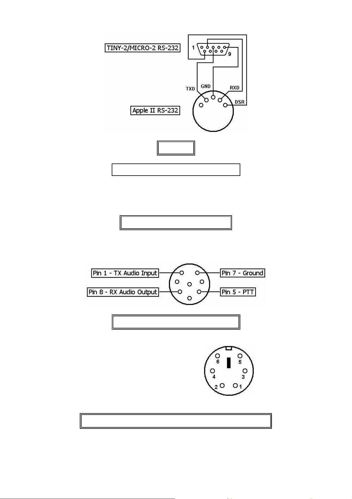
Apple II
Color Computer TINY-2/MICRO-2 RS-232
2 –––––––––––– 2
3 –––––––––––– 5
4 –––––––––––– 3
Tandy/Radio Shack Color Computer
Radio Interfacing Diagrams
ICOM 8-pin (IC-27 etc.) Mic Jack Pinout
1 Data IN
2 GND
3 PTT
4 Data OUT (before Squelch)
5 Squelch
6 Data OUT (after Squelch)
Mini-DIN
Data Output of New Transceivers (TS-2000, FT-817 etc.)
- 26 -

TINY-2/MICRO-2 Technical Ref., 2. Ed 1989
RS-232 Signal Table
The EIA RS-232C Standard
The Electronic Industries Association (EIA) RS-232C Standard defines the interfacing between data
terminal equipment and data communication equipment employing serial binary data interchange.
Electrical signal and mechanical aspects of the interface are well specified. The complete RS-232C
interface consists of 25 data lines. This would seem to be enough signals for a complex parallel
communication line, but many of the 25 lines are very specialized and few are undefined. Most
computer terminals only require from 3 to 5 of these lines to be operational.
Because RS-232C was originally intended for data communications equipment, a few lines must be
swapped between a computer and terminal if no modem of other data communications equipment
is used. These wires are swapped within the cable connecting the two devices. This line is called a
null modem cable.
Pin Description
1 Protective Ground
2 Transmitted Data
3 Received Data
4 Request to Send
5 Clear to Send
6 Data Set Ready
7 Signal Ground (Common Return)
8 Received Line Signal Detector
9 (Reserved for Data Set Testing)
10 (Reserved for Data Set Testing)
11 Unassigned (See section 3.2.3)
12 Sec. Rec'd. Line Sig. Detector
13 Sec. Clear to Send
14 Secondary Transmitted Data
15 Transmission Signal Element Timing (DCE Source)
16 Secondary Received Data
17 Receiver Signal Element Timing (DCE Source)
18 Unassigned
19 Secondary Request to Send
20 Data Terminal Ready
21 Signal Quality Detector
22 Ring Indicator
23 Data Signal Rate Selector (DTE/DCE Source)
24 Transmit Signal Element Timing (DTE Source)
25 Unassigned
- 27 -

TINY-2/MICRO-2 Technical Ref., 2. Ed 1989
Bit-Shifted ASCII Character Table
The characters of AX.25 callsigns are standard 7 bit ASCII characters shifted to occupy the upper 7
bits of the byte. The following table contains the hexadecimal values for the characters of the alphabet and digits 1 - 0 bit shifted one place for use in callsign definitions in packet controller
EPROMs.
Format:
Character
ASCII Hex Bitshifted Hex
A B C D E F G
41 82 42 84 43 86 44 88 45 8A 46 8C 47 8E
H I J K L M N
48 90 49 92 4A 94 4B 96 4C 98 4D 9A 4E 9C
O P Q R S T U
4F 9E 50 A0 51 A2 52 A4 53 A6 54 A8 55 AA
V W X Y Z space
56 AC 57 AE 58 B0 59 B2 5A B4 20 40
1 2 3 4 5 6 7
31 62 32 64 33 66 34 68 35 6A 36 6C 37 6E
8 9 0
38 70 39 72 30 60
Example: Normal hex values for W1AW = 57 31 41 57
Bit-shifted hex values for W1AW = AE 62 82 AE
- 28 -
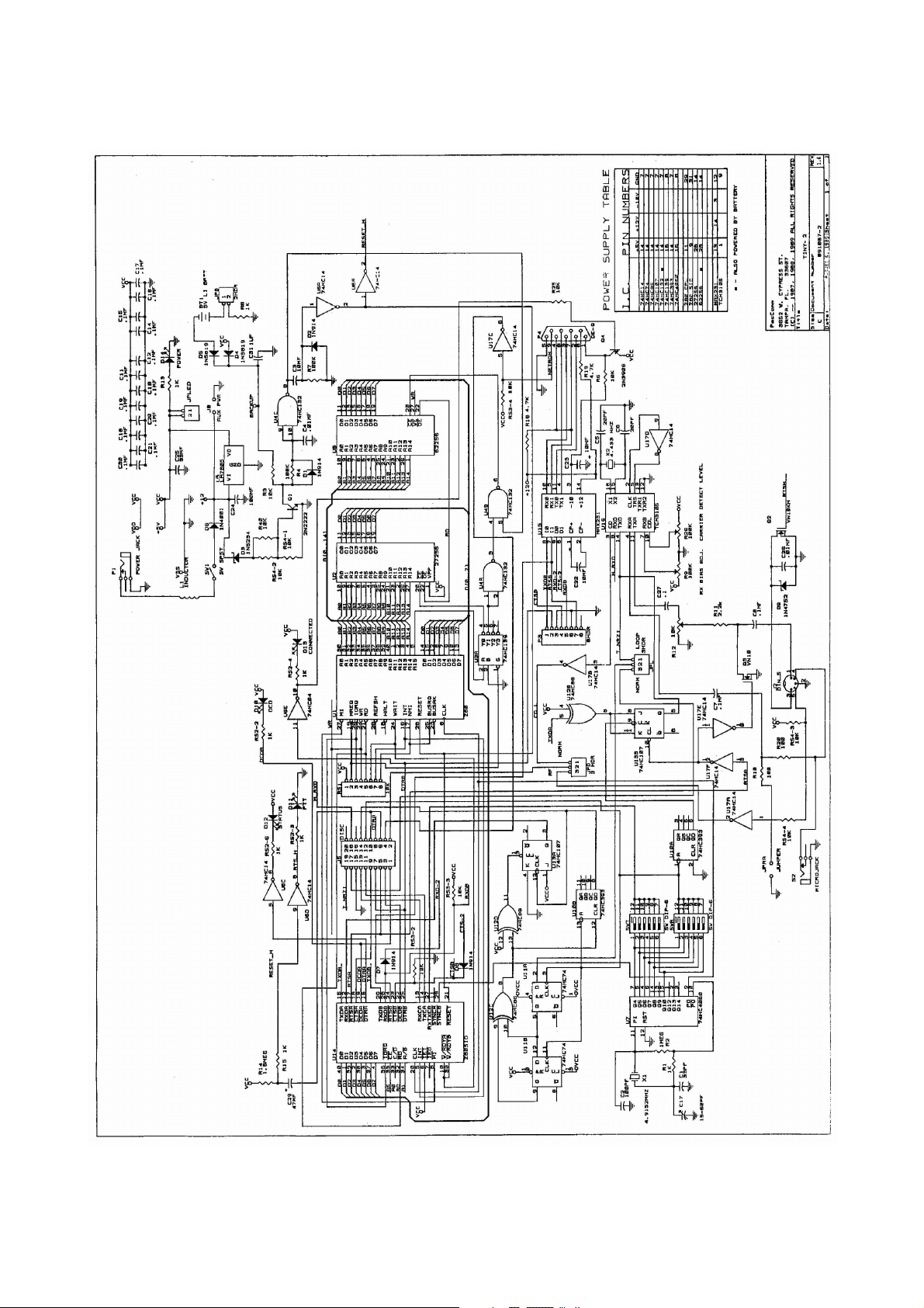
TINY-2/MICRO-2 Technical Ref., 2. Ed 1989
- 29 -
 Loading...