

Paccar SM001-300, SmartAir eHVAC System Service Manual
HVAC
PM820010 Rev. 9 © 9/2016
SERVICE
M
ANUAL
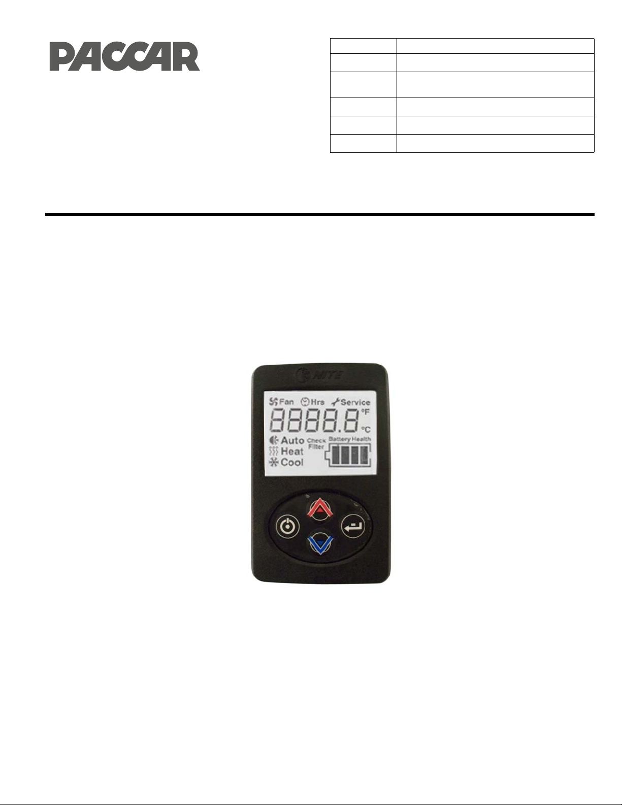
Kenworth Idle Management System
Technical Information and Diagnostic Guide
Section
Title Idle Management System Service Manual
Number
Date Rev. 9 © 9/2016
Model All w/ Idle Management System
Page 1 of 39
HVAC
SM001-300
This guide will assist you in becoming more familiar with the working components
of the Kenworth Idle Management System and the proper steps and procedures to
completely diagnose the Kenworth Idle Management System unit.
©2016 PACCAR Corporation
Confidentiality Notice: This document and the information contained h
in whole or in part, or used for manufacture without the written permission of PACCAR. You are hereby notified that any dissemination of
this information is strictly prohibited.
erein is proprietary. It shall not be reproduced, copied or disclosed,

HVAC: Idle Management System
GENERAL SAFEY INSTRUCTIONS . . . . . . . . . . . . . . . . . . . . . . . . . . . . . . . . . . . . . 5
Warnings, Cautions, and Notes . . . . . . . . . . . . . . . . . . . . . . . . . . . . . . . . . . . 5
Precautions for Working with HFC134a (R134a) Refrigerant and Po lyvinyl Ether
(PVE) Refrigerant Oil . . . . . . . . . . . . . . . . . . . . . . . . . . . . . . . . . . . . . . . . . . . . 5
• Important Safety Notices . . . . . . . . . . . . . . . . . . . . . . . . . . . . . . . . . . . . . 6
EXTERNAL COMPONENT IDENTIFICATION AND LOCATION . . . . . . . . . . . . . . . 8
A. Fuses . . . . . . . . . . . . . . . . . . . . . . . . . . . . . . . . . . . . . . . . . . . . . . . . . . . . . 8
B. Relays . . . . . . . . . . . . . . . . . . . . . . . . . . . . . . . . . . . . . . . . . . . . . . . . . . . . 9
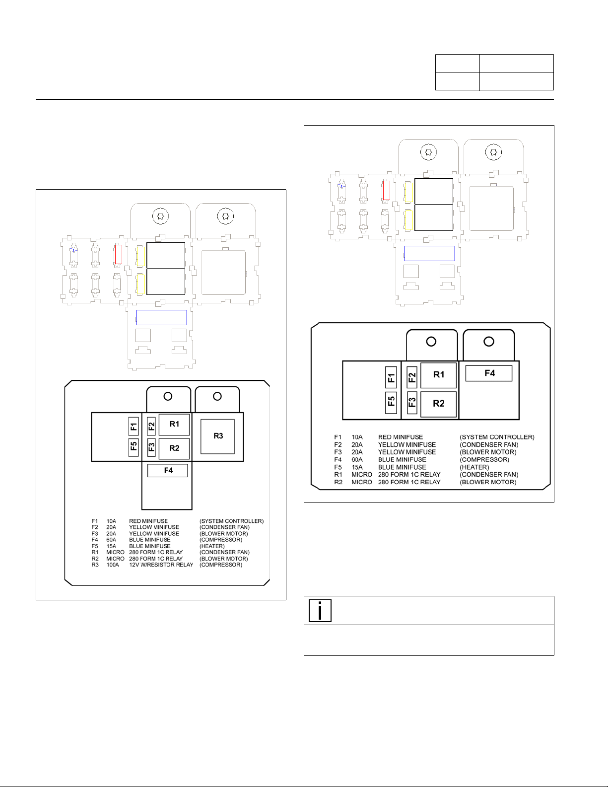
C. Fan and Temperature Control Display LED Display . . . . . . . . . . . . . . . . . 9
D. System and Compressor Con tro lle r . . . . . . . . . . . . . . . . . . . . . . . . . . . . . . 9
E. Linear Power Module . . . . . . . . . . . . . . . . . . . . . . . . . . . . . . . . . . . . . . . . 10
F. Discharge Temperature Sensor – Freeze Switch . . . . . . . . . . . . . . . . . . 10
Page 2 of 39
Number SM001-300
Contents
G. Evaporator Blower . . . . . . . . . . . . . . . . . . . . . . . . . . . . . . . . . . . . . . . . . . 10
H. Condenser Fan . . . . . . . . . . . . . . . . . . . . . . . . . . . . . . . . . . . . . . . . . . . . 10
I. Battery Management System (BMS) . . . . . . . . . . . . . . . . . . . . . . . . . . . . 10
J. Battery Separator . . . . . . . . . . . . . . . . . . . . . . . . . . . . . . . . . . . . . . . . . . . 10
INTERNAL COMPONENTS . . . . . . . . . . . . . . . . . . . . . . . . . . . . . . . . . . . . . . . . . . 12
A. High Pressure Switch . . . . . . . . . . . . . . . . . . . . . . . . . . . . . . . . . . . . . . . . 12
B. Compressor . . . . . . . . . . . . . . . . . . . . . . . . . . . . . . . . . . . . . . . . . . . . . . . 12
C. Thermal Limit Switch on Compressor . . . . . . . . . . . . . . . . . . . . . . . . . . . 12
D. Evaporator Inlet Filter . . . . . . . . . . . . . . . . . . . . . . . . . . . . . . . . . . . . . . . . 12
A/C System Diagnostic . . . . . . . . . . . . . . . . . . . . . . . . . . . . . . . . . . . . . . . . . . . . . . 13
ESPAR Heating System Diagnostic Table . . . . . . . . . . . . . . . . . . . . . . . . . . . . . . . 16
Appendix . . . . . . . . . . . . . . . . . . . . . . . . . . . . . . . . . . . . . . . . . . . . . . . . . . . . . . . . . 18
A. Battery Condition and Performance . . . . . . . . . . . . . . . . . . . . . . . . . . . . . 18
B. Fan and Temperature Control Display . . . . . . . . . . . . . . . . . . . . . . . . . . . 18
C. Relay Testing . . . . . . . . . . . . . . . . . . . . . . . . . . . . . . . . . . . . . . . . . . . . . . 18
D. Pressure Switch Testing . . . . . . . . . . . . . . . . . . . . . . . . . . . . . . . . . . . . . 18
E. Check Continuity Across Fuse Body . . . . . . . . . . . . . . . . . . . . . . . . . . . . 19
F. Discharg e Tem p er at ur e Se nso r /Fre ez e Switch Te stin g . . . . . . . . . . . . . 19
G. Compressor Thermal Limit Switch . . . . . . . . . . . . . . . . . . . . . . . . . . . . . . 19
H. Main Controller/Compressor Contro ller . . . . . . . . . . . . . . . . . . . . . . . . . . 19

HVAC: Idle Management System
I. Condenser Fan Motor Testing . . . . . . . . . . . . . . . . . . . . . . . . . . . . . . . . . .20
J. Evaporator Blower Motor and Linear Power Module Testing . . . . . . . . . .20
K. Compressor Rubber Mounts . . . . . . . . . . . . . . . . . . . . . . . . . . . . . . . . . . .20
L. Testing the Battery Management System (BMS) . . . . . . . . . . . . . . . . . . .21
M. Can Bus . . . . . . . . . . . . . . . . . . . . . . . . . . . . . . . . . . . . . . . . . . . . . . . . . . .22
N. Testing the Espar Heater Connected to the EHVAC Digital Controller . . .22
O. Connecting the System . . . . . . . . . . . . . . . . . . . . . . . . . . . . . . . . . . . . . . .23
P. Evacuating the System . . . . . . . . . . . . . . . . . . . . . . . . . . . . . . . . . . . . . . .24
Q. Charging the Kenworth EHVAC System . . . . . . . . . . . . . . . . . . . . . . . . . .25
Service Instructions for Ring Terminal / Controller and Compressor . . . . . . . . . . . .33
Operation . . . . . . . . . . . . . . . . . . . . . . . . . . . . . . . . . . . . . . . . . . . . . . . . . . . . . . . . .37
Page 3 of 39
Number SM001-300

HVAC: Idle Management System
Page 4 of 39
Number SM001-300
List of Figures
Figure 1. Fuses and Relays . . . . . . . . . . . . . . . . . . . . . . . . . . . . . . . . . . . . . . . . . . . . . . . . . . . . . . . . . . . . . . . . 8
Figure 2.
Figure 3.
Figure 4.
Figure 5.
Figure 6.
Figure 7.
Figure 8.
Figure 9.
Figure 10.
Figure 11.
Figure 12.
Figure 13.
Figure 14.
Figure 15.
Figure 16.
Figure 17.
Figure 18.
Figure 19.
Figure 20.
Figure 21.
Figure 22.
Figure 23.
Figure 24.
Figure 25.
Figure 26.
Figure 27.
Figure 28.
Figure 29.
Fuses and Relays (Units built 8/1/2016 to Present). . . . . . . . . . . . . . . . . . . . . . . . . . . . . . . . . . . . . . . 8
Fan and Temperature Control Display. . . . . . . . . . . . . . . . . . . . . . . . . . . . . . . . . . . . . . . . . . . . . . . . . 9
System and Compressor Controller. . . . . . . . . . . . . . . . . . . . . . . . . . . . . . . . . . . . . . . . . . . . . . . . . . . 9
Linear Power Module. . . . . . . . . . . . . . . . . . . . . . . . . . . . . . . . . . . . . . . . . . . . . . . . . . . . . . . . . . . . . 10
Discharge Temperature Sensor. . . . . . . . . . . . . . . . . . . . . . . . . . . . . . . . . . . . . . . . . . . . . . . . . . . . . 10
Evaporator Blower and Condenser Fan. . . . . . . . . . . . . . . . . . . . . . . . . . . . . . . . . . . . . . . . . . . . . . . 10
Battery Management System. . . . . . . . . . . . . . . . . . . . . . . . . . . . . . . . . . . . . . . . . . . . . . . . . . . . . . . 10
Battery Separator Solenoid, located in the battery box.. . . . . . . . . . . . . . . . . . . . . . . . . . . . . . . . . . . 11
Automated Battery Disconnect Solenoid, located in the battery box. . . . . . . . . . . . . . . . . . . . . . . . . 11
High Pressure Switch. . . . . . . . . . . . . . . . . . . . . . . . . . . . . . . . . . . . . . . . . . . . . . . . . . . . . . . . . . . . . 12
Compressor . . . . . . . . . . . . . . . . . . . . . . . . . . . . . . . . . . . . . . . . . . . . . . . . . . . . . . . . . . . . . . . . . . . . 12
Thermal Limit Switch on Compressor . . . . . . . . . . . . . . . . . . . . . . . . . . . . . . . . . . . . . . . . . . . . . . . . 12
Evaporator Inlet Filter. . . . . . . . . . . . . . . . . . . . . . . . . . . . . . . . . . . . . . . . . . . . . . . . . . . . . . . . . . . . . 12
Relay Testing. . . . . . . . . . . . . . . . . . . . . . . . . . . . . . . . . . . . . . . . . . . . . . . . . . . . . . . . . . . . . . . . . . . 18
Service Equipment. . . . . . . . . . . . . . . . . . . . . . . . . . . . . . . . . . . . . . . . . . . . . . . . . . . . . . . . . . . . . . . 23
Service Recovery Connections . . . . . . . . . . . . . . . . . . . . . . . . . . . . . . . . . . . . . . . . . . . . . . . . . . . . . 24
Internal Wiring Diagram (Before 8/1/2016) . . . . . . . . . . . . . . . . . . . . . . . . . . . . . . . . . . . . . . . . . . . . 28
External Wiring Diagram . . . . . . . . . . . . . . . . . . . . . . . . . . . . . . . . . . . . . . . . . . . . . . . . . . . . . . . . . . 29
Wiring Diagram (8/1/2016 to Present) . . . . . . . . . . . . . . . . . . . . . . . . . . . . . . . . . . . . . . . . . . . . . . . . 30
On/Off Button. . . . . . . . . . . . . . . . . . . . . . . . . . . . . . . . . . . . . . . . . . . . . . . . . . . . . . . . . . . . . . . . . . . 37
Changing Mode . . . . . . . . . . . . . . . . . . . . . . . . . . . . . . . . . . . . . . . . . . . . . . . . . . . . . . . . . . . . . . . . . 37
Changing Blower Speeds. . . . . . . . . . . . . . . . . . . . . . . . . . . . . . . . . . . . . . . . . . . . . . . . . . . . . . . . . . 37
Changing Temperature . . . . . . . . . . . . . . . . . . . . . . . . . . . . . . . . . . . . . . . . . . . . . . . . . . . . . . . . . . . 37
View System Runtime/Hours . . . . . . . . . . . . . . . . . . . . . . . . . . . . . . . . . . . . . . . . . . . . . . . . . . . . . . . 38
Change from °F to °C. . . . . . . . . . . . . . . . . . . . . . . . . . . . . . . . . . . . . . . . . . . . . . . . . . . . . . . . . . . . . 38
Enter Service Mode . . . . . . . . . . . . . . . . . . . . . . . . . . . . . . . . . . . . . . . . . . . . . . . . . . . . . . . . . . . . . . 38
Service Screens. . . . . . . . . . . . . . . . . . . . . . . . . . . . . . . . . . . . . . . . . . . . . . . . . . . . . . . . . . . . . . . . . 39
EHVAC Filter . . . . . . . . . . . . . . . . . . . . . . . . . . . . . . . . . . . . . . . . . . . . . . . . . . . . . . . . . . . . . . . . . . . 39

HVAC: Idle Management System
GENERAL SAFEY INSTRUCTIONS
Page 5 of 39
Number SM001-300
A number of alerting messages are in this manual.
Please read and follow them. They are there for your protection and information. These
avoid injury to yourself or others and help prevent costly
damage to the vehicle.
messages can help you
Warnings, Cautions, and Notes
Key symbols and “signal words” are used to indicate
what kind of message is going to follow. Pay special
attention to instructions prefaced by symbols and signal
words “WARNING”, “CAUTION”, or “NOTE”. Please do
not ignore any of these alerts.
WARNING!
When you see this symbol and word, the messa g e th a t
follows is especially vital. This signals something that
can cause injury or even death. This message will tell
you what the hazard is, what can happen if you don’t
heed the warning, and/or how to avoid it.
CAUTION
• The air conditioning system uses HFC134a
(R134a) refrigerant and polyvinyl ether (PVE)
refrigerant oil, which are not compatible with
CFC-12 (R12) refrigerant, mineral oil, or PAG
oil. If the refrigerants or oils are mixed the compressor may fail.
• Do not attempt to use R-12 servicing equipment;
damage
ing equipment will result.
• Use only service equipment that is U.L. listed and
is
to remove HFC134a (R134a) from the air conditioning system.
• Verify the HFC134a (R134a ) refri gerant i n the vehi cle system and the recycling equipment/recovery
ank are contaminant free by using a refrigerant
t
identifier.
to the air condition system or your servic-
certified to meet the requirements of SAE J2210
NOTE
CAUTION
This symbol and word signals something that could
damage your vehicle.
NOTE
This symbol gives you information we believe to be
helpful. The information can be a service hint or something to assist with the r
epairing of the vehicle.
Precautions for Working with HFC134a
(R134a) Refrigerant and Polyvinyl Ether
(PVE) Refrigerant Oil
WARNING!
• DO NOT breathe A/C refrigerant and oil vapor or
mist. Exposure may irritate eyes, nose and throat.
• Additional health and safety information may be
btained from refrigerant and oil manufacturers.
o
• If accidental system disc
work area before resuming service.
harge occurs, ventilate
THIS SYSTEM MUST BE SERVICED BY QUALIFIED
PERSONNEL ONLY.
R134a service equipment or vehicle air conditioning
systems shou
with compressed air.
• This air conditioning system may contain R134a
orescent dye for leak detection. Inspect with a
flu
high intensity ultraviolet light system.
• A label on the unit will identify sy
cent dye.
ld not be pressure tested or leak tested
stems with fluores-
NOTE
The Air Conditioning system is designed for use only
with the specified polyvinyl ether (PVE) refrigerant oil
for HFC134a (R134a) A/C systems and HFC134a
(R134a) components. Idemitsu FVC68D PVE oil is the
ONLY recommended oil. The PVE oil is very Hygroscopic. Hygroscopic means that it
out proper sealing, oil will become moisture saturated
d should not be used.
an
absorbs water. With-
HVAC: Idle Management System
NOTE
Take care to follow the handling procedures below:
• Only use the specified FV
sealed container.
• Immediately reseal containers of oil.
• To avoid contamination, do not return oil to original
tainer once it is dispensed, and never mix it
con
with other refrigerant oils.
• Do not allow PVE oil to come in contact with Styrofoam parts. Damage may occur.
• Do not allow PVE oil to come in c
cle paint. Damage may occur.
• If any connection in the refrigerant loop is opened it
uld be closed as soon as possible in order to
sho
minimize the amount of moisture that enters the
system.
• Any components that are replaced should have
ust caps left in place until the component is ready
d
to be installed in the refrigerant loop.
• Any component removed from th e refrigerant loop
ould have dust caps in place as soon as possible
sh
in order to minimize moisture intrusion.
C68D PVE oil from a
ontact with vehi-
Important Safety Notices
WARNING!
Improper practices, carelessness, or ignoring any
warnings may cause death, personal injury, equipment
or property damage.
Read and understand all of the safety precautions and
nings before performing any repair. This list contains
war
the general safety precautions that must be followed to
provide personal safety. Special safety precautions are
included in the procedures when they apply.
Work areas should be dry, well lit, ventilated, and be free
m clutter, loose tools, parts, ignition sources and haz-
fro
ardous substances. Be aware of ha
that can exist.
• Wear protective glasses and protective shoes when
working.
• Rotating parts can cause cuts, mutilation or strangulation.
zardous conditions
Page 6 of 39
Number SM001-300
• Do not wear loose-fitting or torn clothing. Remove all
jewelry before
• Before beginning any repair, disconnect the battery
negative [-] cable) from both battery boxes and dis-
(
charge any capacitors.
• Disconnect the air starting motor, if equipped, to prevent accidental engine starting.
•Put a “DO N
compartment or on the controls.
• Allow the engine to cool before beginning any repair.
• Always use blocks or proper stands to support the
icle or vehicle components before performing any
veh
service work. Do not work on anything that is supported only by lifting jacks or a hoist.
• To reduce the possibility of personal injury, use a
ist or get assistance when lifting components that
ho
weigh 23 kg [50 lb] or more. Ensure all lifting devices
such as chains, hooks, or slings are in good condition and are of the correct load capacity. Make sure
y lifting devices are positioned correctly. Always
an
use a spreader bar when necessary. The lifting
hooks must not be side-loaded.
• Corrosion inhibitors and lubrica ting oils may contain
li. Do not get the substance in eyes and avoid
alka
prolonged or repeated contact with skin. Do n ot swallow. In case of contact, immediately wash
soap and water. In case of harmful contact, immediately contact a physician. Alway
cals OUT OF REACH OF CHILDREN.
• Naptha and Methyl Ethyl Ketone (MEK) are flammable materials and must be used with caution. Follow
the ma
when using these materials. Always keep any
chemicals OUT OF REACH OF CHILDREN.
• When working on the vehicle, be alert for hot part s on
systems
flow, and hot fluids in lines, tubes, and compartments. Contact with any hot surface may cause
rns.
bu
• Always use tools that are in good condition. Make
e you have the proper understanding of how to
sur
use the tools before performing any service work.
Use ONLY genuine replacement parts from PACCAR.
• Always use the same fastener part number (or equ ivalent) when replacing items. Do
lesser quality if replacements are necessary.
working.
OT OPERATE” tag in the operator's
skin with
s keep any chemi-
nufacturer's instructions to ensure safety
that have just been turned off, exhaust gas
not use a fastener of

HVAC: Idle Management System
Page 7 of 39
Number SM001-300
• Do not perform any repair when impaired, tired,
fatigued or after consuming alcohol or drugs that can
impair your functioning.
• Some state and federal agencies in the United States
of America have determined that used engine oil can
be carcinogenic and can cause reproductive toxicity.
Avoid inhalation of vapors, ingestion, and prolonged
contact with used engine oil.
• Liquefied petroleum gas is heavier than air and can
accumulate near the floor, in sumps, and low-lying
areas.
• Close the manual fuel valves prior to performing
maintenance and repairs, and when storing the vehi
cle inside.
• California Proposition 65 Warning – Diesel engine
exhaust and some of its constituents are known to
the State of California to cause cancer, birth defects,
and other reproductive harm.
• DO NOT breathe A/C refrigerant and oil vapor or
mist. Exposure may irritate eyes, nose and throat.
• Additional health and safety information may be
obtained from refrigerant and oil manufacturers.
• If accidental system discharge occurs, ventilate work
area before resuming service.
-
HVAC: Idle Management System
EXTERNAL COMPONENT
IDENTIFICATION AND LOCATION
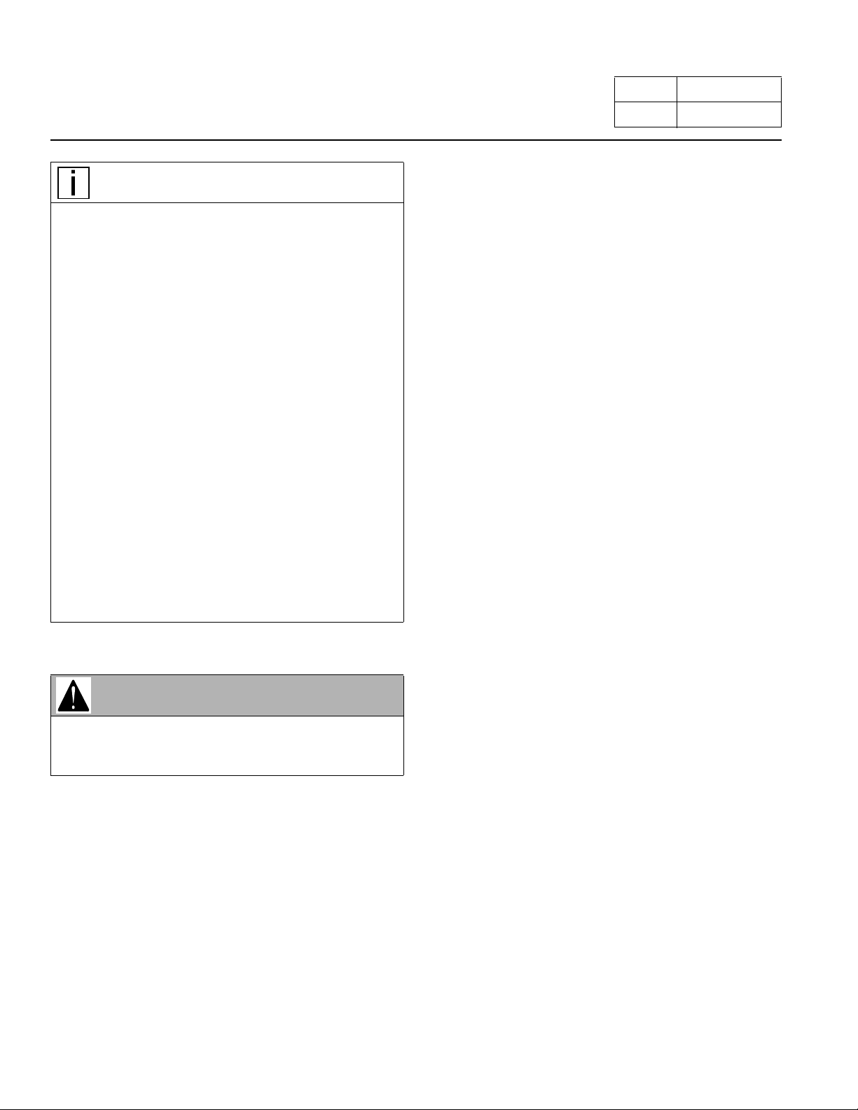
A. Fuses
Page 8 of 39
Number SM001-300
Figure 1. Fuses and Relays
Figure 2. Fuses and Relays (Units built 8/1/2016 to
Present)
F1 Fuse 10 Amp (Mini)
This fuse provides short circuit prot ection for the System
rol.
cont
NOTE
Removing fuse F1 for 10-15 seconds will reset the system controller to factory default settings.
Location: on the control center.
F2 Fuse 10 Amp (Mini)
This fuse provides short circuit protection for the condenser fan.
HVAC: Idle Management System
Location: on the control center.
F3 Fuse 20 Amp (Mini)
This fuse provides short circuit protect ion for the evaporator blower.
Location: on the control center.
F4 Fuse 60 Amp (Maxi)
This fuse provides short circuit protection for the compressor.
Location: on the control center.
B. Relays
Location: on the control center.
R1. This relay controls the voltage to the condenser fan.
Page 9 of 39
Number SM001-300
R2. This relay controls the vo
module and evaporator blower.
R3. This relay controls the v
controller.
ltage to the linear power
oltage to the compressor
C. Fan and Temperature Control Display
LED Display
Allows for temperature and Blower speed adjustment of
the EHVAC (Electrical Heating and Ventilation Air Conditioning) unit when operating in Auto, cool or heat mode.
Unit – stops when unit is shut off or batteries are
A/C
depleted.
Figure 3. Fan and Temperature Control Display
Auxiliary heater will shut down when batteries are
depleted but will continue to run through the cool down
cycle. Also displays hours of service, battery health and
service items.
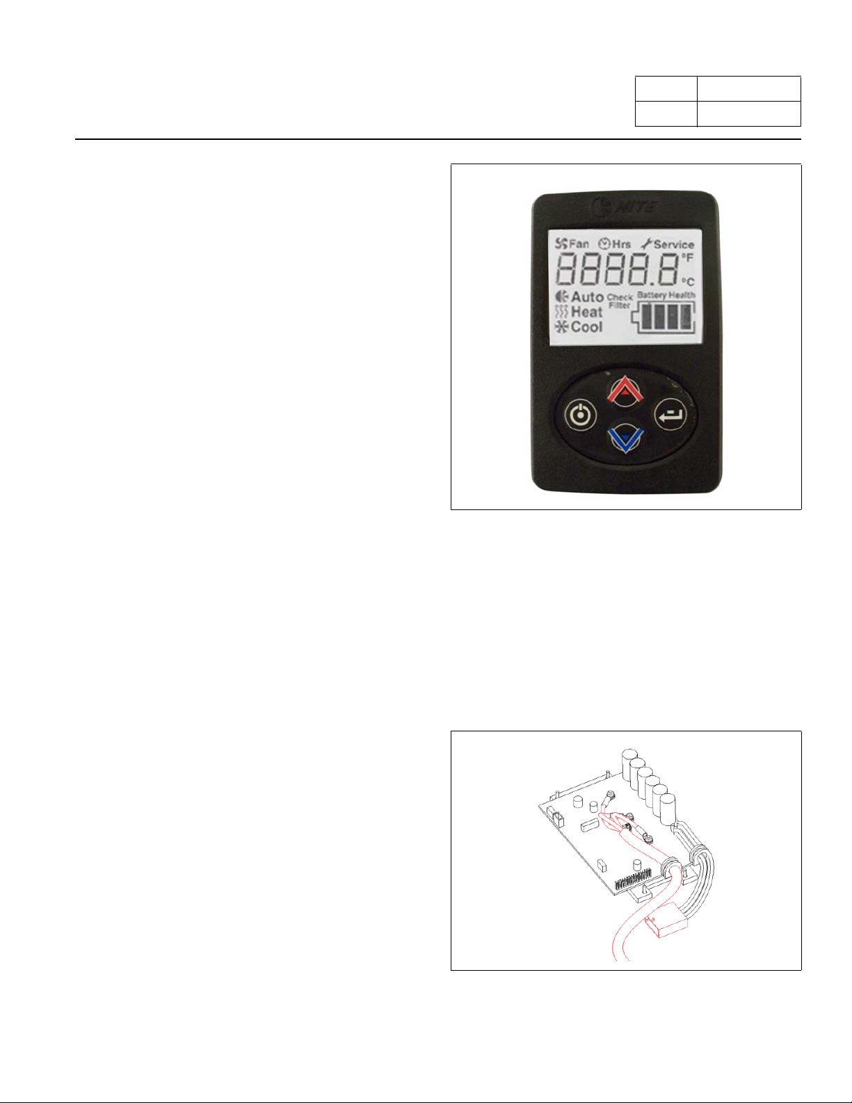
D. System and Compressor Controller
This device controls the unit and the output voltage to the
variable speed compressor. It is located under the large
access cover.
Figure 4. System and Compressor Controller
HVAC: Idle Management System
E. Linear Power Module
This module controls the amount of voltage delivered to
the evaporator blower creating variable blower speeds. It
is located in the return air in front of the evaporator coil.
Figure 5. Linear Power Module
F. Discharge Temperature Sensor – Freeze
Switch
Page 10 of 39
Number SM001-300
Figure 7. Evaporator Blower and Condenser Fan
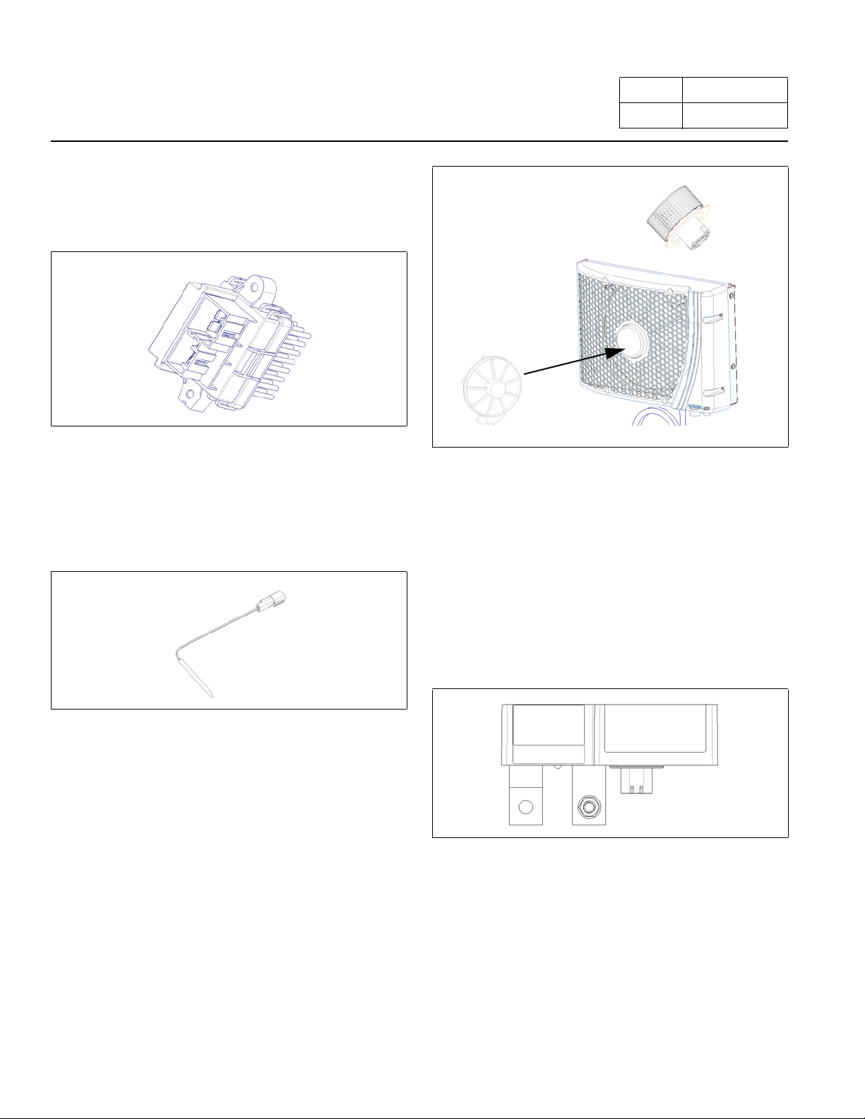
I. Battery Management System (BMS)
This sensor monitors the evaporator outlet temperature
as it enters the vehicle duct system.
Figure 6. Discharge Temperature Sensor
G. Evaporator Blower
This blower pulls air through the evaporator coil and
blows conditioned air into the interior of the sleeper.
H. Condenser Fan
This blower draws air through the condenser coil to cool
the refrigerant flowing through the system.
This device monitors the auxiliary batteries for state of
charge, communicates with the EHVAC system and controls the battery separator solenoid. LED light on this
vice indicates power to the device and does not pro-
de
vide diagnostics. Power inputs to this device are fuse
otected.
pr
If one of the BMS fuses blows, the solenoid will disen-
gage.
Figure 8. Battery Management System
J. Battery Separator
This device connects the truck batteries to the EHVAC
batteries. When the starting batteries are at or above
13.2 volts, the battery management device will engage
the solenoid to allow the alternator to charge the auxiliary
batteries. When the voltage drops to or below 12.5 vo lts
the battery management system will disengage the solenoid to prevent the truck starting batteries from being dis charged below the engine start level.
HVAC: Idle Management System
Figure 9. Battery Separator Solenoid, located in the
battery box.
Page 11 of 39
Number SM001-300
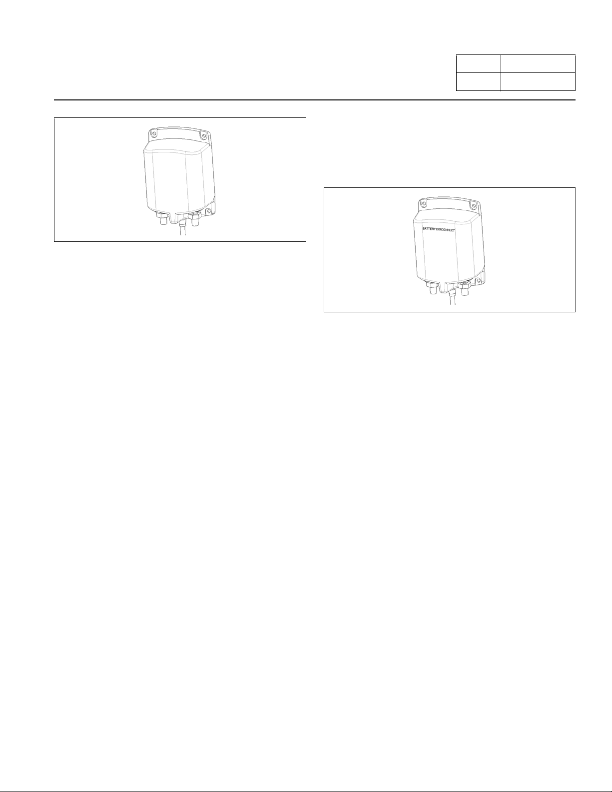
Automated Battery Disconnect (Option)
This device disconnects the EHVAC batteries from the
AC unit when the cab disconnect switch is set to
EHV
OFF. The cab disconnect switch must be set to ON for
the EHVAC unit to operate.
Figure 10. Automated Battery Disconnect Solenoid,
located in the battery box.

HVAC: Idle Management System
INTERNAL COMPONENTS
A. High Pressure Switch
This normally closed brazed pressure switch will open
and prevent the operation of the compressor due to high
internal pressure. It is NOT serviceable.
Figure 11. High Pressure Switch
Page 12 of 39
Number SM001-300
B. Compressor
This unit is part of the hermetically sealed refrigeration
system.
Figure 12. Compressor
C. Thermal Limit Switch on Compressor
This is a normally closed (auto reset) switch to protect
the compressor from high temperature.
Figure 13. Thermal Limit Switch on Compressor
D. Evaporator Inlet Filter
This filter protects the evaporator coil from dust and
debris. It is washable and should be serviced periodically
during routine maintenance.
Figure 14. Evaporator Inlet Filter
When necessary, the Check Filter indicator will notify you
that the EHVAC filter must be cleaned or changed. To
reset “Check Filter” – at screen 1 press and hold enter
button for 3 seconds.
 Loading...