

Paccar Peterbilt 587 Owner's Manual

© 2010 PACCAR INC - All Rights Reserved
This manual illustrates and describes the operation of features or equipment which may be either standard or optional on this vehicle. This
manual may also include a description of features and equipment which are no longer available or were not ordered on this vehicle. Please
disregard any illustrations or descriptions relating to the features or equipment which are not on this vehicle.
Peterbilt reserves the right to discontinue, change specifications, or change the desing of its vehicles at any time without notice and without
incurring any obligation.
Quick Table of Contents
Introduction . . . . . . . . . . . . . . . . . . 1
Cab And Frame Access . . . . . . . . . . . . 6
Getting To Your Engine . . . . . . . . . . . . . . 11
Controls And Displays. . . . . . . . . . . . . . . . . . . 14
Seat And Restraint Systems . . . . . . . . . . . . . . . . . 75
Driver’s Checklists . . . . . . . . . . . . . . . . . . . . . . . . . . . 88
Starting And Operating The Vehicle . . . . . . . . . . . . . . . . . . 93
Maintenance and Service . . . . . . . . . . . . . . . . . . . . . . . . . . 143
Vehicle Identification . . . . . . . . . . . . . . . . . . . . . . . . . . . . . . . . . . . 229
Consumer Information . . . . . . . . . . . . . . . . . . . . . . . . . . . . . . . . . . . . . 230
Subject Index . . . . . . . . . . . . . . . . . . . . . . . . . . . . . . . . . . . . . . . . . . . . . . . 233
Y53-6032.book Page 2 Monday, May 24, 2010 3:37 PM

PART 1: INTRODUCTION HOW TO FIND WHAT YOU WANT
PART 1: INTRODUCTION
This manual contains useful information for the safe and
efficient operation of your Peterbilt Model 587. It also provides information on maintaining your vehicle in the best
condition, with an outline for performing safety checks and
basic preventive maintenance inspections.
We have tried to present the information you’ll need to
learn about your vehicle’s functions, controls, and operation—and to present it as clearly as possible. We hope
you’ll find this manual easy to use.
Please remember, though—this manual is not a training
manual. It can’t tell you everything you need to know
about driving your Peterbilt vehicle. For that you need a
good training program or truck driving school. If you have
not been trained, get the proper training before you drive.
Only qualified drivers should drive this vehicle.
There will be times when you need to take this manual out
of your Peterbilt. When you do, please be sure to return it
to the cab when you are finished using it. That way it will
be there when you need it the next time or when you pass
How To Find What You Want
There are several tools built into this manual to help you
find what you need quickly and easily.
First is the Quick Table of Contents. Located at the front
of the manual, this lists the main subjects covered and
gives page numbers where you can find these subjects.
Use the Quick Table of Contents to find information on a
large subject like “Maintenance.”
Cross-referenced citations also help you get the information you need. If some other part of the manual contains
further information on the subject you are reading about,
we’ll indicate that in a cross-reference like this: (See
“
PART 6: DRIVER’S CHECKLIST”). You won’t have to go
searching for more information.
Finally you’ll find a helpful Subject Index. It’s in the back
of the manual and alphabetically lists the subjects covered. So if you want information on brakes, for example,
just look under Brake in the Subject Index. You’ll find all
Y53-6032.book Page 1 Monday, May 24, 2010 3:37 PM

A SPECIAL WORD ABOUT REPAIRS PART 1: INTRODUCTION
A Special Word About Repairs
Your Peterbilt dealer’s service center is the best place to
have your vehicle repaired. You can find Peterbilt dealers all
over the country with the equipment and trained personnel
to get you back on the road quickly—and keep you there.
Your vehicle is a complex machine. Anyone attempting
repairs on it needs good mechanical training and the
proper tools. If you are sure you have these requirements,
then you can probably perform some repairs yourself.
However, all warranty repairs must be performed by an
authorized Peterbilt service facility. If you aren’t an experienced mechanic, or don’t have the right equipment,
please leave all repairs to an authorized service facility.
They are the ones equipped to do the job safely and correctly.
WARNING! Attempting repair work without sufficient training, service manuals, and the proper
tools can be dangerous for yourself and others.
You could be injured or you could make your
truck unsafe and cause death or serious injury.
Do only those tasks you are fully qualified to do.
Maintenance Manuals. If you do decide to do any complex repair work, you’ll need the Peterbilt Maintenance
manuals. Order them from your authorized dealer. Please
provide your Chassis Serial Number when you order, to
be sure you get the correct manuals for your vehicle. Allow
about four weeks for delivery. There will be a charge for
these manuals.
Final Chassis Bill of Material. A complete, nonillustrated
computer printout listing of the parts used to custom-build
your Peterbilt vehicle is available through the Peterbilt
dealer from whom your purchased your vehicle.
WARNING! Modifying your vehicle can make it
unsafe. Some modifications can affect your
truck’s electrical system, stability, or other
important functions. Before modifying your
vehicle, check with your dealer to make sure it
can be done safely.
Additional Sources of Information
Operator’s manuals are also supplied by the manufacturers of components such as the engine, seats, transmission, and radio in your Peterbilt. If you are missing any of
Y53-6032.book Page 2 Monday, May 24, 2010 3:37 PM
PART 1: INTRODUCTION SAFETY SIGNALS
Another place to learn more about trucking is a local truck
driving school. Contact one near you to find out what
kinds of instruction it offers.
Federal agencies such as The National Highway Traffic
Safety Administration and the Federal Motor Carrier
Safety Administration also have information and various
agencies in state governments are sources for regulations
that differ from state to state.
Safety Signals
A number of alerting messages are in this manual. Please
read and follow them. They are there for your protection
and information. These messages can help you avoid
injury to yourself and others, as well as prevent costly
damages to the vehicle.
Key symbols and “signal words” are used to indicate what
kind of message is going to follow. Pay special attention to
instructions prefaced by symbols and the signal words
“WARNING”, “CAUTION”, and “NOTE”. Please do not
ignore any of these alerts.
WARNING
When you see this word, the message that follows is especially vital. It signals a potentially
hazardous situation which, if not avoided, could
result in an injury or death. This message will tell
you what the hazard is, what can happen if you
don't heed the warning, and how to avoid it.
Example:
WARNING! Never carry additional fuel containers in the vehicle. Such containers, full or
empty, may leak, explode or cause a fire in the
event of a collision.
CAUTION
Signals a potentially hazardous situation
which, if not avoided, could result in property or
vehicle damage.
Example:
CAUTION: Continuing to operate your vehicle
with insufficient oil pressure will cause seri-
Y53-6032.book Page 3 Monday, May 24, 2010 3:37 PM
VEHICLE SAFETY PART 1: INTRODUCTION
NOTE
Provides general information: for example, the
note may suggest how to operate the vehicle
more efficiently.
Example:
NOTE: Pumping the accelerator will not assist in
starting the engine.
Vehicle Safety
Make sure your Peterbilt is in top working condition before
heading out on the road—it is the responsible driver's duty
to do so. Inspect the vehicle according to “
PART 6:
DRIVER’S CHECKLIST”.
WARNING! Do not drink and drive. Your
reflexes, perceptions, and judgment can be
affected by even a small amount of alcohol.
You could have a serious—or even fatal accident—if you drive after drinking. Please do
not drink and drive or ride with a driver who
has been drinking.
WARNING! The use of alcohol, drugs, and certain medications will seriously impair perception, reactions, and driving ability. These
circumstances can substantially increase the
risk of an accident and death or personal
injury.
Please remember, this manual is not a training manual. It
cannot tell you everything you need to know about driving
your Peterbilt vehicle. For that you need a good training
Please take the time to read these messages when
you see them, and remember:
WARNING!
Something that could seriously injure or kill you or others.
CAUTION:
Something that could cause property or vehicle damage.
NOTE:
Useful information.
Y53-6032.book Page 4 Monday, May 24, 2010 3:37 PM

PART 1: INTRODUCTION VEHICLE SAFETY
program or truck driving school. If you have not been
trained, get the proper training before you drive. Only
qualified drivers should drive this vehicle.
Safe driving is only possible with the proper concentration
on the driving task. Keep distraction to a minimum to
improve your concentration. Examples of distractions
may include radio controls, GPS navigation controls, cellular telephone calls, cellular text messages, reading or
reaching for something on the floor. Minimizing your distractions will improve safe driving and will help avoid an
accident involving death or personal injury.
Be aware of local regulations that may prohibit the use of
cellular telephones while driving. In addition to being an
unsafe practice, it may be against local ordinances to use
cellular devices while operating the vehicle.
Every new Peterbilt vehicle is designed to conform to all
Federal Motor Vehicle Safety Standards applicable at the
time of manufacture. However, even with these safety features, continued safe and reliable operation depends
greatly upon regular vehicle maintenance. The vehicle
must be operated within the range of its mechanical capabilities and the limits of its load ratings. (See the Tire and
Rim Weight Ratings label on the driver's door edge.)
Y53-6032.book Page 5 Monday, May 24, 2010 3:37 PM

PART 2: GETTING INTO & OUT OF THE CAB AND FRAME ACCESS
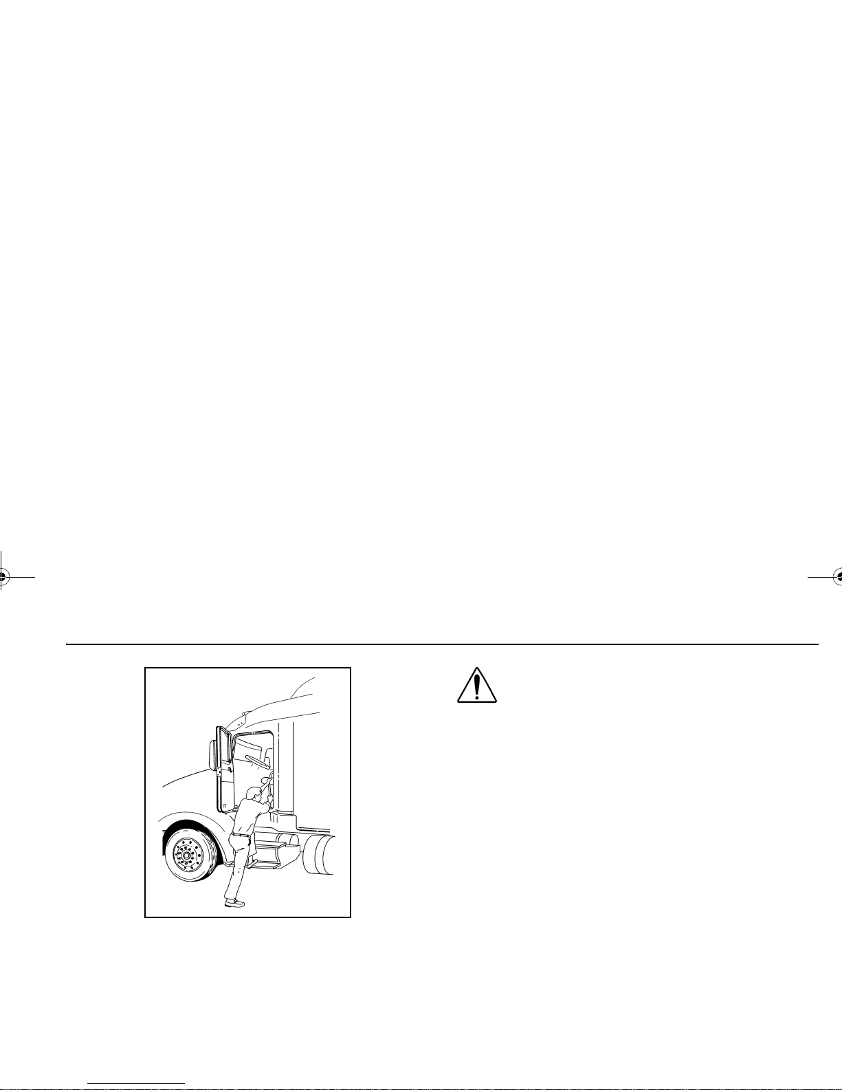
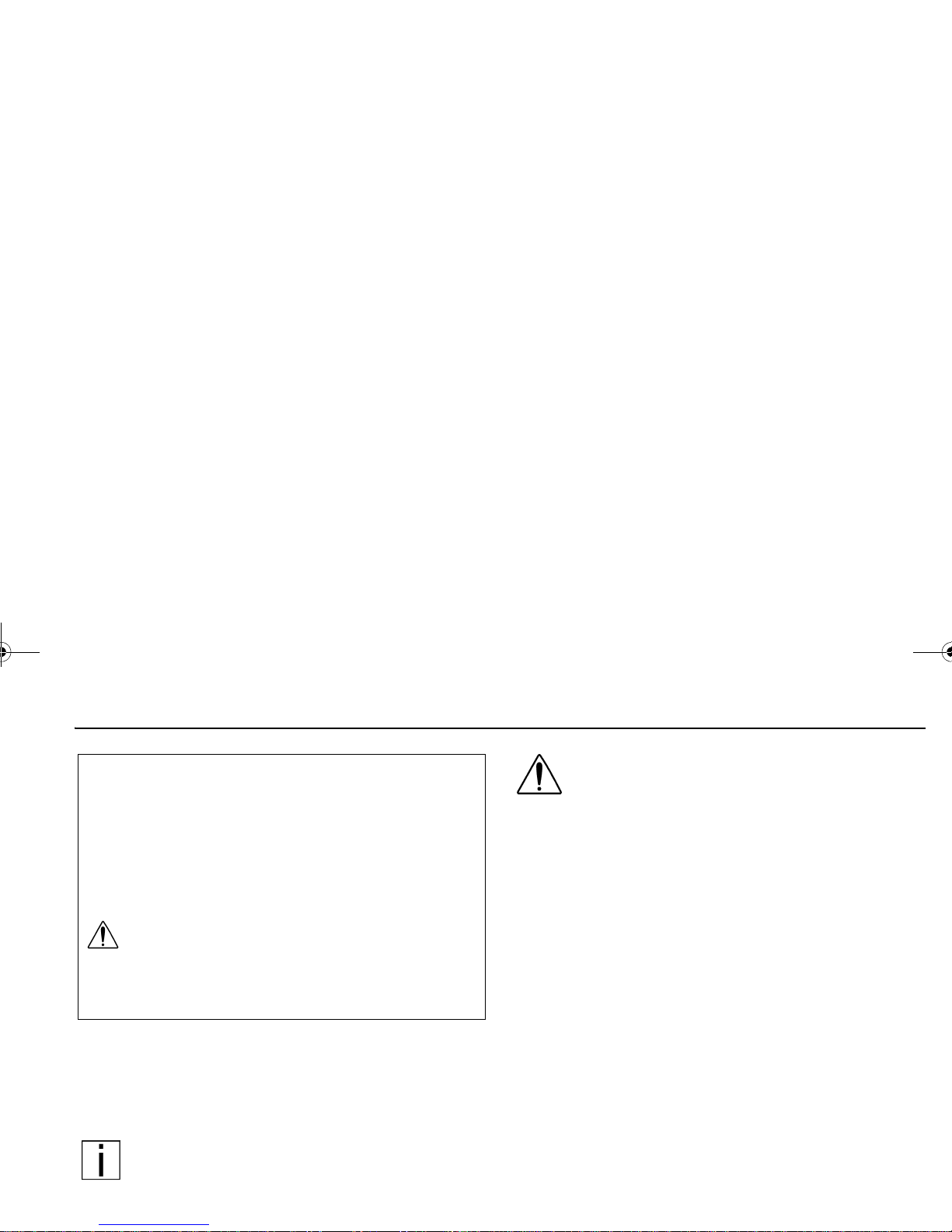
PART 2: GETTING INTO & OUT OF THE CAB AND FRAME ACCESS
Be careful whenever you get into or out of your vehicle’s
cab. Always maintain at least three points of contact with
your hands on the grab handles and your feet on the
steps.
WARNING! Do not jump out of the cab or get
into the cab without proper caution. You could
slip or fall, possibly suffering death or serious
injury. You could slip and fall if the steps are
wet or icy, or if you step in fuel, oil, grease,
snow or mud.
The illustrations that follow show the best ways to enter
and exit a cab.
Vehicle With External Grab Handle
02958-A
Y53-6032.book Page 6 Monday, May 24, 2010 3:37 PM
PART 2: GETTING INTO & OUT OF THE CAB AND FRAME ACCESS DOOR LOCK AND KEYS
Vehicle Without External Grab Handle
Door Lock and Keys
Doors can be locked from the inside by using the lock button. Close the door then push the button down to lock.
Doors automatically unlock when you open them from
inside, and can be locked from the outside with the key
only. To lock or unlock the doors from outside the cab,
insert the key in the lock. Turn the key toward the rear to
WARNING! To help lessen the chance and/or
severity of death or personal injury in case of
an accident, always lock the doors while driving. Along with using the lap shoulder belts
properly, locking the doors helps prevent
doors from inadvertently opening and occupants from being ejected from the vehicle.
Remote Keyless Entry (optional)
This vehicle may be equipped with a Remote Keyless
Entry (RKE) system that adds security and convenience
to your vehicle. The system will lock or unlock the driver’s
door and passenger’s door with the key fob and alert you
with parking lights when the selected door’s are locked or
unlocked. The system includes two key fobs that provide
secure rolling code technology that prevents someone
from recording the entry signal.
Operation
To unlock the driver’s door, press the UNLOCK button
once. The driver's door will unlock and the parking lights
will come on for 40 seconds.
To unlock the passenger’s door press the UNLOCK button
02958-B
Y53-6032.book Page 7 Monday, May 24, 2010 3:37 PM

DOOR LOCK AND KEYS PART 2: GETTING INTO & OUT OF THE CAB AND FRAME ACCESS
To lock both doors press the LOCK button. The doors will
lock and the parking lights will come on for 2 seconds. If
the doors are open they will not lock. The range of the
RKE system should be approximately 30 ft. This will be
reduced if it is operated close to other RF sources such as
TV/radio transmitters and cell towers.
Batteries
The key fob uses one CR2032, 3V battery. Batteries
should last approximately three years, depending on use.
Consistently reduced range is an indicator that the battery
needs replacement. Batteries are available at most discount, hardware and drug stores.
The battery is located under the back cover of the key fob.
Be sure to synchonize the key fob every time you replace
the batteries.
Synchronization
The key fob may need to be synchronized to the truck
when the battery is replaced or when the key fob has not
been used for an extended period time.
To Synchronize A Key Fob
1. Hold the key fob near the receiver.
NOTE: The receiver is located behind the
Speedometer/Tachometer cluster assembly.
2. Press and hold both the Lock and Unlock buttons at
the same time for approximately 7 seconds.
3. When the key fob is resynchronized, the doors will
lock then immediately unlock.
4. If the fob fails to synchronize, it could be programmed
to a different truck or could have failed. Contact your
dealer to re-program your key fob.
Y53-6032.book Page 8 Monday, May 24, 2010 3:37 PM
PART 2: GETTING INTO & OUT OF THE CAB AND FRAME ACCESS CLIMBING ONTO THE DECK PLATE
Climbing Onto the Deck Plate
When you are climbing onto and off the deck plate, maintain at least three points of contact with your hands on the
grab handles and your feet on the steps.
NOTE: Any alteration (adding bulkheads, headache racks, tool boxes, etc.) behind the cab or
sleeper that affects the utilization of grab handles,
deck plates, or frame access steps installed by
Peterbilt must comply with FMCSR 399.
WARNING! Do not step on vehicle components without antiskid surfaces or use components not designed for entry-and-exit use.
You could fall and kill or injure yourself if you
step onto a slippery surface. For example:
• Do not step onto the surface of a fuel tank.
A fuel tank is not a step. The tank surface
can get very slippery, and you might not be
able to prevent a fall.
• Use only the steps and handholds provided,
not chain hooks, quarter fenders, etc.
• Do not climb onto and off the deck plate—
use steps and grab handle provided. If there
is no deck plate, or if proper steps and grab
handles are not provided, do not climb onto
the area behind the cab.
• Do not climb onto or stand on the frame
rails. The frame rails are very slippery and
could cause you to fall, resulting in death or
personal injury.
• Always reinstall steps before entering the
cab or accessing the deck plate. Without
steps, you could slip and fall, resulting in
FCC ID: L2C0031T IC: 3432A-0031T
FCC ID: L2C0032R IC: 3432A-0032R
This device complies with Part 15 of the FCC Rules and with RSS-210
of Industry Canada. Operation is subject to the following two conditions:
1. This device may not cause harmful interference, and
2. This device must accept any interference received, including
interference that may cause undesired operation.
WARNING: Changes or modifications not expressively
approved by the party responsible for compliance could
void the user's authority to operate the equipment. The
term “IC:” before the radio certification number only signifies that Industry Canada technical specifications were
met.
Y53-6032.book Page 9 Monday, May 24, 2010 3:37 PM
CLIMBING ONTO THE DECK PLATE PART 2: GETTING INTO & OUT OF THE CAB AND FRAME ACCESS
Hold handles as you step up
Three points of contact as you reach the deck area
Y53-6032.book Page 10 Monday, May 24, 2010 3:37 PM
PART 3: GETTING TO YOUR ENGINE HOOD HOLD DOWNS
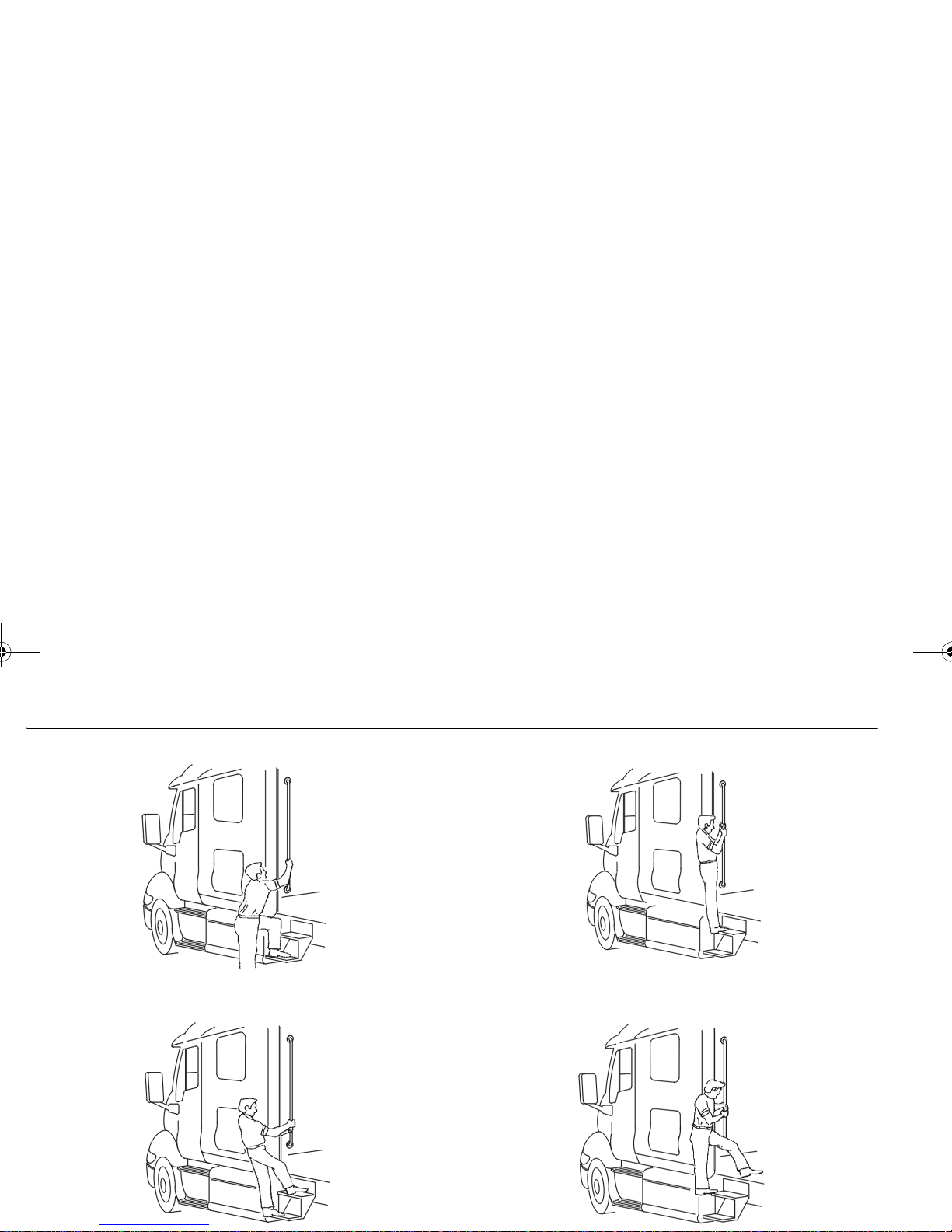
PART 3: GETTING TO YOUR ENGINE
Hood Hold Downs
Hood hold downs keep a hood from opening unexpectedly.
CAUTION: A hood not latched securely could
open during operation and cause vehicle
damage. Be sure to latch the hood securely.
Hood Tilt
Follow this procedure to tilt the hood.
WARNING! A pivoting hood could hurt someone or be damaged itself. Before opening or
closing the hood, be sure there are no people
or objects in the way. Failure to stand in a
position of safety can cause death or personal
injury.
1. To open your hood, unlock the hood hold downs by
unlatching them. Put one hand on the top of the hood
front, one foot on the bumper, and one foot on the
ground. Tilt the hood forward.
LATCHED
UNLATCHED
Y53-6032.book Page 11 Monday, May 24, 2010 3:37 PM
HOOD TILT PART 3: GETTING TO YOUR ENGINE
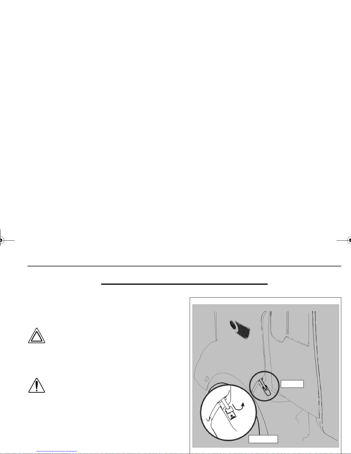
2. Locate the hood anti-blowdown device mounted to the
driver side hood dampener.
WARNING! The hood uses two struts to control movement during opening and closing.
Do not tilt the hood with one or both struts
disconnected. Replace damaged, worn, or
leaking struts as soon as possible. Tilting a
hood with either strut disconnected or defective may cause the hood to tilt too rapidly.
You could be killed or injured and the hood
could be damaged.
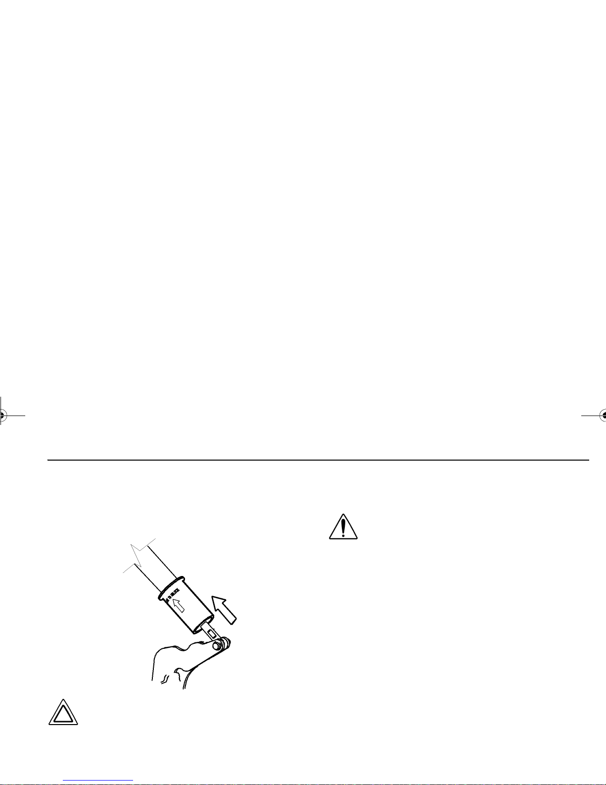
3. Verify that the device was previously reset during the
last hood closing event. This is done by pulling the
collar in the downward direction.
WARNING! Always verify that the hood antiblowdown device has been reset when opening the hood. The device is reset either by
fully closing the hood or by manually pulling
the device down. Failure to reset the antiblowdown device may lead to a hood closing unintentially which can cause death or personal
injury to anyone under the hood.
PULL DOWN TO
RESET DEVICE
Y53-6032.book Page 12 Monday, May 24, 2010 3:37 PM
PART 3: GETTING TO YOUR ENGINE HOOD TILT
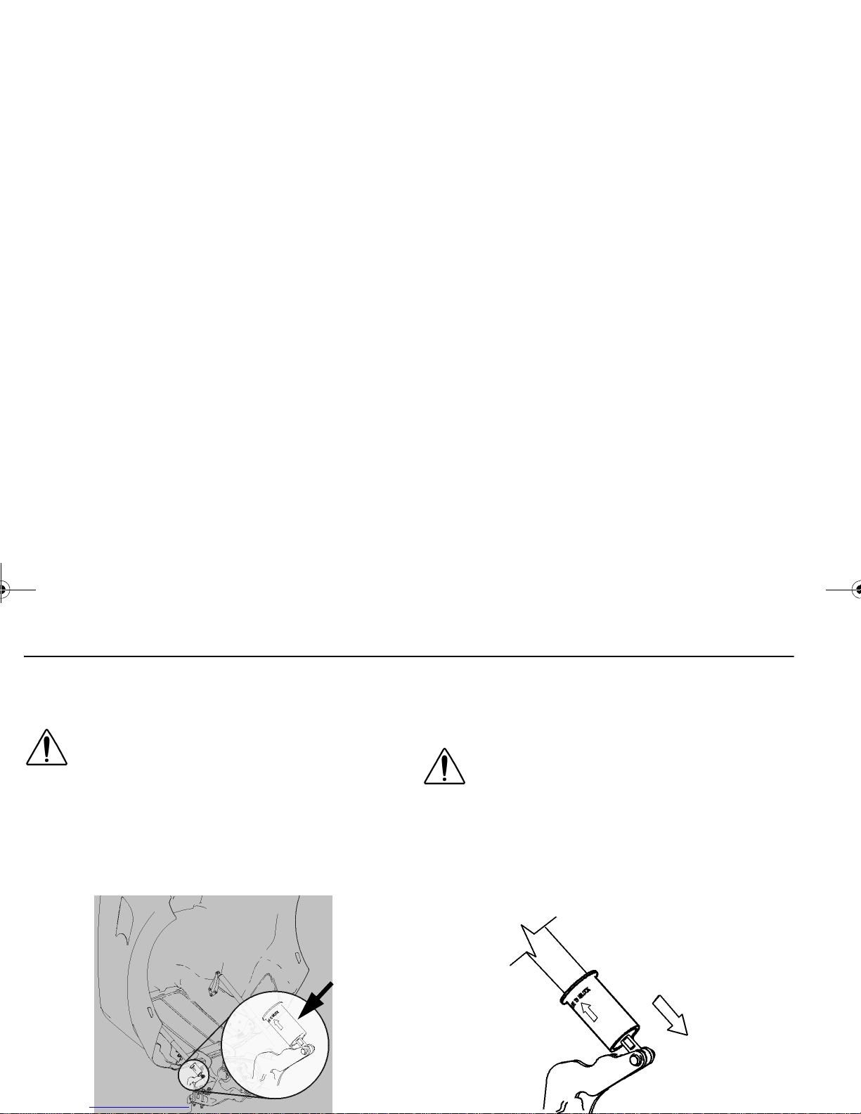
4. To close the hood, disengage the hood antiblowdown
device by pushing it in the upward direction. The
device will move about 1/4” up the shaft. You may feel
a click when the device disengages.
CAUTION: Attempting to close a hood without
disengaging the hood antiblowdown device
may cause equipment or vehicle damage.
5. Firmly push upward and rearward on the hood ornament to start the hood tilting backwards. Continue to
push until the hood comes is fully closed.
6. Secure the hood latches on both sides of the vehicle
to hold the hood in the closed position.
WARNING! If the hood is not latched securely,
it could open during operation and cause an
accident involving death or injury. Be sure the
hood is latched securely before moving the
vehicle
.
PUSH UP TO
DISENGAGE
DEVICE
Y53-6032.book Page 13 Monday, May 24, 2010 3:37 PM
YOUR INSTRUMENT PANEL PART 4: CONTROLS AND DISPLAYS
PART 4: CONTROLS AND DISPLAYS
This part explains the location of the various features on
your vehicle and describes their function. For information
on using these features in driving, see the paragraphs
below.
Your Instrument Panel
Please remember that each vehicle is custom-made. Your
instrument panel may not look exactly like the one in the
pictures that follow.
We have tried to describe the most common features and
controls available, so your vehicle may not have some of
the ones that appear in this section. You can pick out the
parts that apply to you and read them to be fully informed
on how your particular vehicle operates.
WARNING! Use extreme caution when using
devices while driving (such as cellular telephones) that distracts you from safe driving
practices. Failure to properly concentrate on
the driving task can result in an accident
involving death or personal injury. Limit the
use of such devices to when it is safe to do
so; not while operating the vehicle.
Y53-6032.book Page 14 Monday, May 24, 2010 3:37 PM
PART 4: CONTROLS AND DISPLAYS YOUR INSTRUMENT PANEL
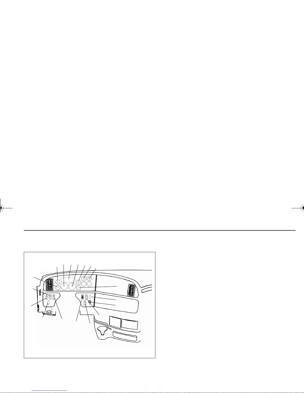
Typical Cab Instruments and Controls
LEFT SIDE
1. Hazard Switch 10. Oil Pressure
2. Ignition Switch 11. Primary Air Pressure
3. Headlight Light Switch 12. Secondary Air Pressure
4. ID/Clearance Lamps Switch 13. Fuel
5. Voltmeter 14. Cigarette Lighter
6. Engine Coolant Temp 15. Menu Control Switch
7. Tachometer 16. Rear A/C Switch
8. Driver Information Display 17. Dome Light Switch
9. Speedometer 18.
Panel Dimmer
18
17
16
15
14
13
12
11
10
8
7
6
5
4
3
9
2
1
Y53-6032.book Page 15 Monday, May 24, 2010 3:37 PM
YOUR INSTRUMENT PANEL PART 4: CONTROLS AND DISPLAYS
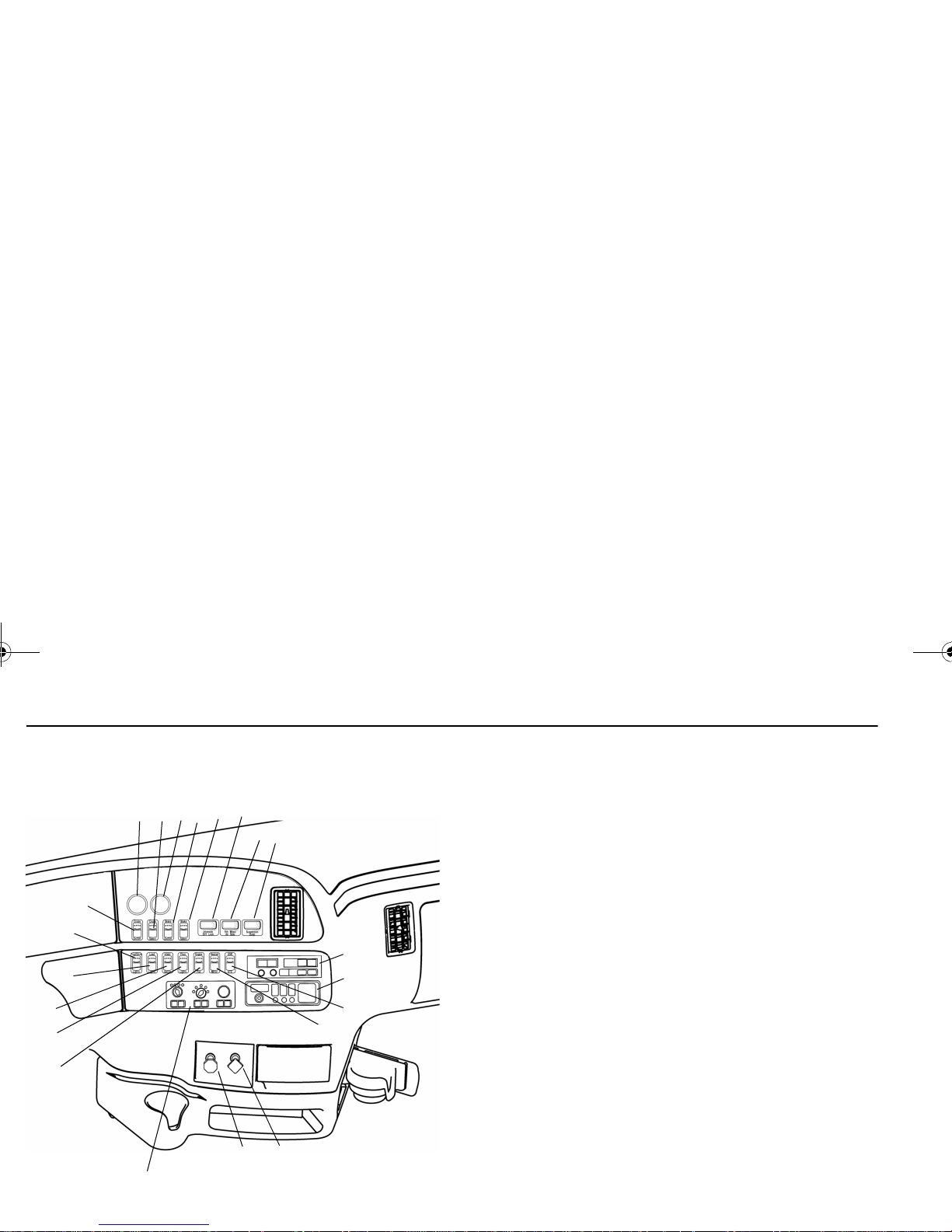
RIGHT SIDE
1. Parking Brake Valve 12. Optional
2. Trailer Air Supply Valve 13. Engine Brake
3. Heater/AC Control Panel 14. Engine Brake Sel
4. Engine Fan Switch 15. Interaxle Differential Lock
Switch
5. Floor Light Switch 16. 5th Wheel Lock Switch
6. Regeneration Switch 17. Air Suspension Switch
7. Load Light Switch 18. Radio
8. Fog Lights Switch 19. CB Radio
9. Cruise Control Switch 20. Traction Control Switch
10. Transmission Temperature 21. Mirror Heater Switch
11. Cruise Control Sel Switch
19
18
20
21
1
2
3
4
5
6
7
8
9
10
11
12
13
14
15
16
17
Y53-6032.book Page 16 Monday, May 24, 2010 3:37 PM
PART 4: CONTROLS AND DISPLAYS INSTRUMENTS AND CONTROLS
Instruments And Controls
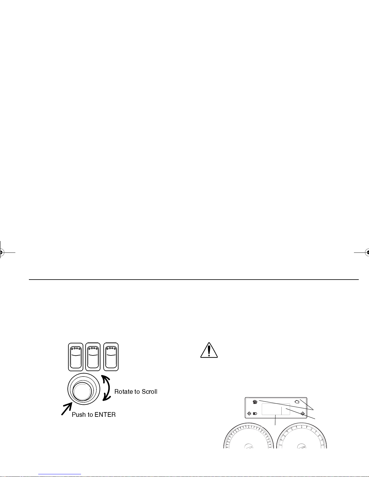
Menu Control Switch (MCS)
The MCS is used to navigate the Driver Information Display unit.
The Menu Control Switch is located on the D Panel
as shown in the illustration below.
The MCS has the following functions:
• Rotating the MCS
– Selecting display
– Setting values
• Pushing the MCS
Standard Warning Lights and Audible Alarm
The warning lights and audible alarm may indicate a system malfunction. Check the lights frequently, and respond
properly as soon as you see one go on. These lights could
save you from a serious accident.
WARNING! Do not ignore a warning light or
audbile alarm. These signals tell you something is wrong with your vehicle. It could be a
failure in an important system, such as the
brakes, which could lead to an accident
involving death or personal injury. Have the
appropriate system checked immediately.
1. Driver Information Display 2. Status Indicator
3. Light Bar
3
2
1
Y53-6032.book Page 17 Monday, May 24, 2010 3:37 PM

INSTRUMENTS AND CONTROLS PART 4: CONTROLS AND DISPLAYS
Warning lights and indicator symbols will be shown in both
areas 1 and 2. Area 3 includes the turn and high beam
indicator symbols.
1. Driver Information Display:
The display can show up to six warning lights. Warnings
do not have fixed positions and are displayed in order of
criticality. The most critical warning will be displayed on
the top row and to the left. If more than six warnings are
active, the menu control switch (MCS) can be used to
scroll through the additional warnings.
2. Status Indicator:
Additional lights and indicator symbols are displayed in
the Status Indicator. They are limited to:
a. Park Brake
b. Transmission Gear (Automatic transmissions
only)
c. Warnings:
d. Cruise Control - active
e. Clock alarm bell
Refer to “Warning Light / Indicator Symbols” on page 20
for information on each symbol.
Instrument System Self Test:
When the ignition switch is turned on the instrumentation
system will undergo a Self Test. This test will verify the
operation of the gauges and warnings.
During the Instrumentation System Self Test, three
screens will sequentially display warning icons (approximately 3 seconds each screen) on the Information Display. These are:
Number of active warnings.
A red warning is active.
An amber warning is active.
Y53-6032.book Page 18 Monday, May 24, 2010 3:37 PM
PART 4: CONTROLS AND DISPLAYS INSTRUMENTS AND CONTROLS
Refer to “Warning Light / Indicator Symbols” on page 20
for information on each symbol.
Completing this sequence will indicate a successful Self
Test. Have your instrumentation system checked by a
qualitfied service technician if does not successfully complete.
Audible Alarm:
The audible alarm will sound during the Instrumentation
System Self Test. The audible alarm will also sound in
include but are not limited to headlight on, fifth wheel, stop
engine, primary/secondary air, and driver door open
warnings.
Optional Lights:
Additional lights may be operational depending on individual vehicle specifications. These will be included in the
Instrument System Self Test.
NOTE: Some optional lights may illuminate even
though your vehicle is not equipped with that particular feature.
First
Second
Third
Y53-6032.book Page 19 Monday, May 24, 2010 3:37 PM
INSTRUMENTS AND CONTROLS PART 4: CONTROLS AND DISPLAYS
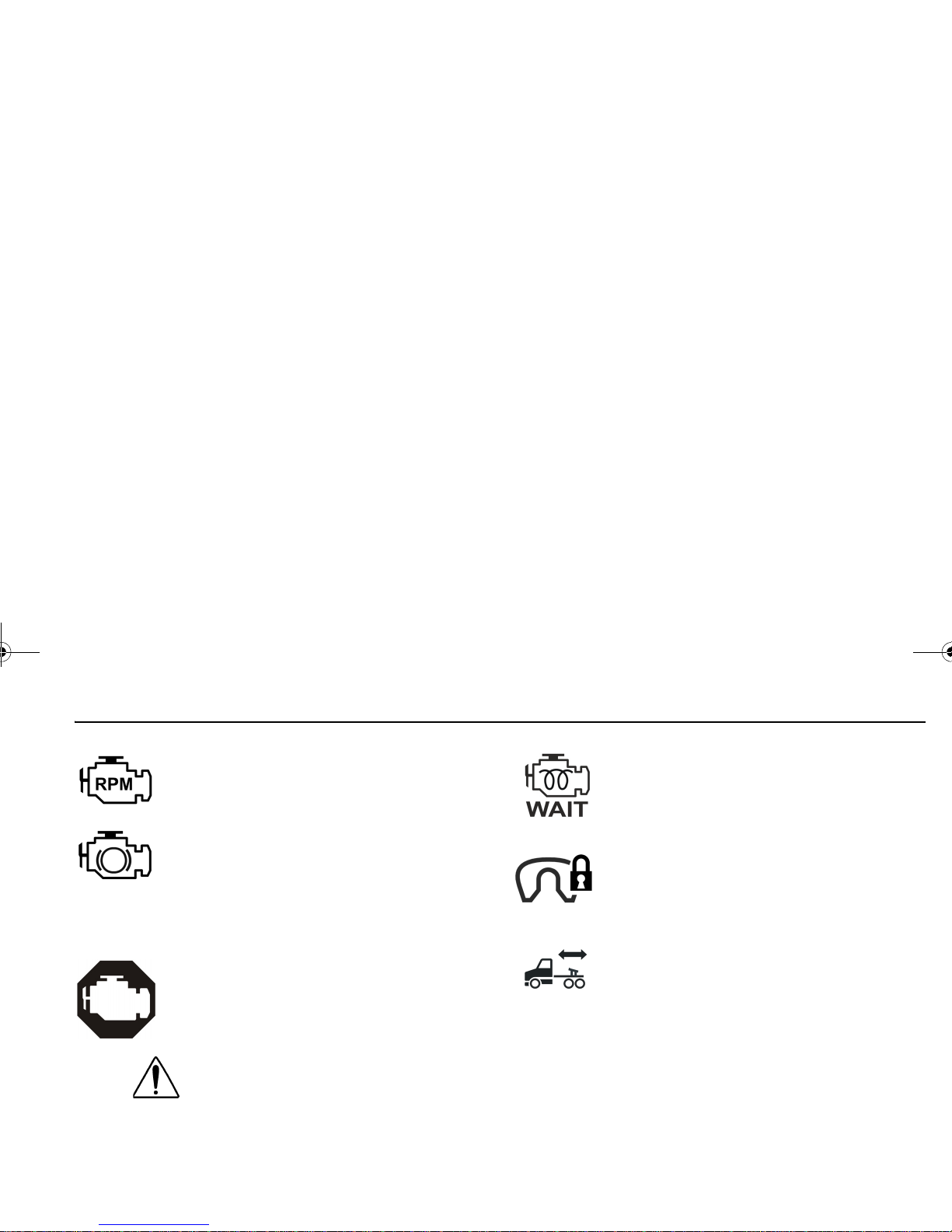
Warning Light / Indicator Symbols
The following is a list of Warning Light / Indicator Symbols.
Reading left to right, the table header identifies
• the Symbol Name
• the appearance of the Symbol
• the Symbol Color when it is illuminated
• whether the symbol is standard (Std) or optional (Opt)
• the Page Number reference for additional information
Symbols are listed by major component sections.
Example: Engine, and then in alphabetical order.
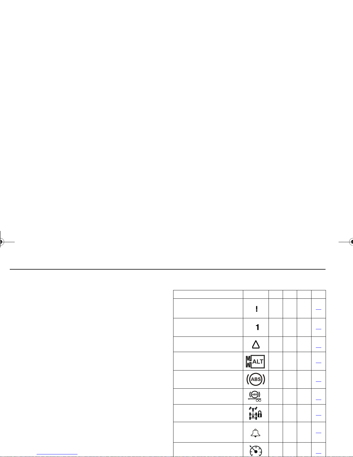
Warning Light / Indicator Symbols
Symbol Name Symbol Color Std Opt Page
1. Active Warnings, Exclamation
Point
Red
23
2. Active Warnings, Number
Yellow
23
3. Active Warnings, Triangle
Yellow
23
4. Alternator
Red
23
5. Anti-Lock Brake System
(ABS)
Yellow
23
6. Anti-Lock Brake System
(ABS), Trailer
Yellow
24
7. Axle, Inter-Axle Differential
Locked (Tandem Axles)
Yellow
24
8. Clock, Alarm Bell
Yellow
24
9. Cruise Control, Active
Yellow
24
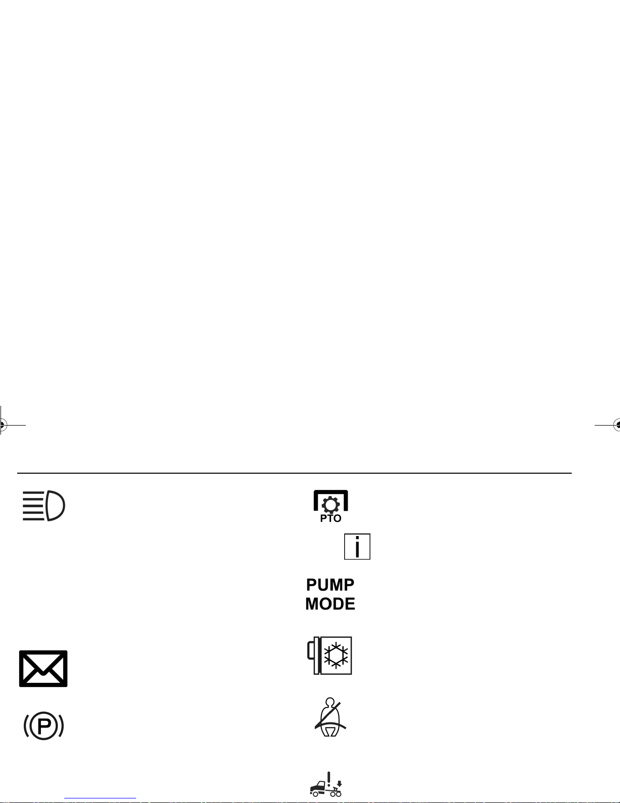
Y53-6032.book Page 20 Monday, May 24, 2010 3:37 PM
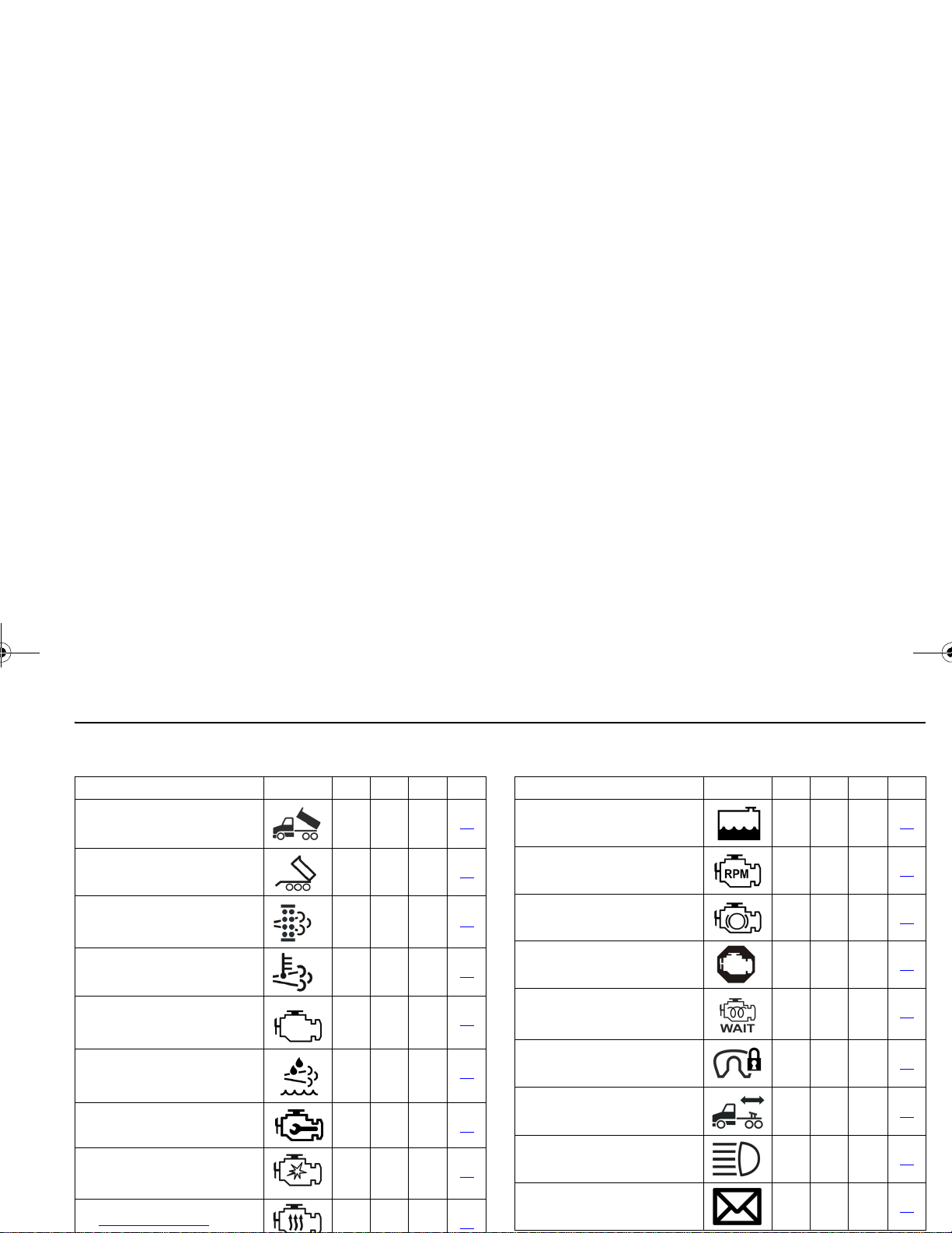
PART 4: CONTROLS AND DISPLAYS INSTRUMENTS AND CONTROLS
10. Dump Truck, Body Up
Yellow
24
11. Dump Truck, Trailer Body Up
Yellow
25
12. Emissions, Diesel Particulate Filter (DPF)
Yellow
25
13. Emissions, High Exhaust
System Temperture (HEST)
Yellow
25
14. Emissions, Malfunction Indicator Lamp
Yellow
26
15. Emission, Diesel Exhaust
Fluid Lamp
Yellow
26
16. Engine, Check Engine
Yellow
26
17. Engine, Ether Start
Green
26
18. Engine, Heater
Yellow
26
Warning Light / Indicator Symbols
Symbol Name Symbol Color Std Opt Page
19. Engine, Low Coolant Level
Yellow
26
20. Engine, Overspeed
Red
27
21. Engine, Retarder (Brake)
Green
27
22. Engine, Stop Engine
Red
27
23. Engine, Wait To Start
Yellow
27
24. Fifth Wheel, King Pin Lock
Red
27
25. Fifth Wheel, Slide Unlocked
Red
27
26. Lights, High Beam
Blue
28
27. Message Waiting
Green
28
Warning Light / Indicator Symbols
Symbol Name Symbol Color Std Opt Page
Y53-6032.book Page 21 Monday, May 24, 2010 3:37 PM

INSTRUMENTS AND CONTROLS PART 4: CONTROLS AND DISPLAYS
28. Park Brake
Red
28
29. Power Take-off (PTO)
Green
28
30. Power Take-off (PTO), Pump
Mode
Green
28
31. Refrigerator
Green
28
32. Seat Belt, Fasten
Red
28
33. Suspension Dump
Yellow
28
34. Tire Inflation
Yellow
29
35. Transmission, Auxiliary
Yellow
29
36. Transmission, Check
Red
29
Warning Light / Indicator Symbols
Symbol Name Symbol Color Std Opt Page
37. Transmission, Do Not Shift
Red
29
38. Transmission, Oil Filter
Yellow
29
39. Transmission, Oil Temperature High
Yellow
29
40. Turn Signal, Left
Green
29
41. Turn Signal, Right
Green
29
Warning Light / Indicator Symbols
Symbol Name Symbol Color Std Opt Page
Y53-6032.book Page 22 Monday, May 24, 2010 3:37 PM
PART 4: CONTROLS AND DISPLAYS INSTRUMENTS AND CONTROLS
Warning Light/Indicator Symbol Descriptions
1. Active Warnings, Exclamation Point
Illuminates when a red warning is active. Use
the MCS knob to view the warnings that are
active. Refer to the preceeding Figure ,
“Warning Light / Indicator Symbols,” on
page 20 for warning color classification.
2. Active Warnings, Number
Illuminates the total number of red and yellow
active warnings.
Use the MCS to view the
active warnings if the display shows a > symbol.
3. Active Warnings, Triangle
Illuminates when an yellow warning is active.
Use the MCS knob to view the warnings that
are active. Refer to the preceeding Figure ,
“Warning Light / Indicator Symbols,” on
page 20 for warning color classification.
4. Alternator
Illuminates if the alternator is not charging.
(For alternators with warning lamp output
signal.)
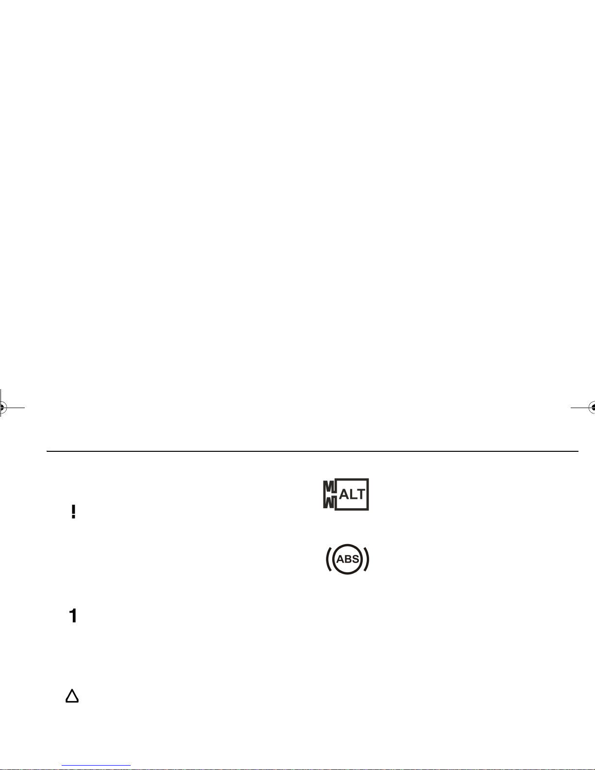
5. Anti-Lock Brake System (ABS)
Illuminates during the Instrumentation System Self Test. Have the ABS system checked
by a Peterbilt dealer if the ABS Warning
Lamp stays on for more than 3 seconds.
Illuminates during normal operating conditions to indicate a problem with the ABS System. See “ABS Warning Lamps” on page 109
for more information.
Illuminates when a problem exists with the
optional Wheel Spin Control feature. See
“Advanced ABS with Stability Control” on
page 106 more information.
Y53-6032.book Page 23 Monday, May 24, 2010 3:37 PM
INSTRUMENTS AND CONTROLS PART 4: CONTROLS AND DISPLAYS
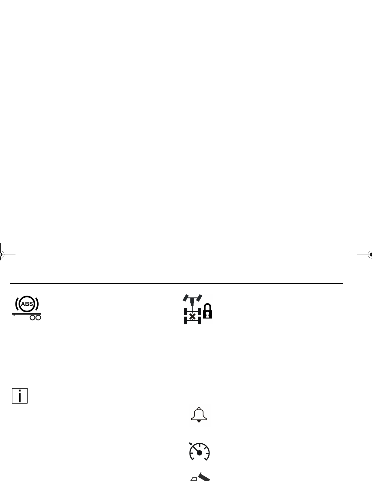
6.Anti-Lock Brake System (ABS), Trailer
Illuminates during the Instrumentation System Self Test and the tractor/truck is connected with a ABS equipped trailer.
Illuminates during normal operating conditions to indicate a problem with the Trailer
ABS System. This should be checked by a
Peterbilt dealer as soon as possible. See
“Truck/Tractor ABS Warning Lamp” on
page 109 for more information.
NOTE: Tractors/Trucks and trailers built after 3/1/
01 must be able to turn on an In-Cab Trailer ABS
Warning Lamp (per U.S. FMVSS121). The industry chose Power Line Communication (PLC) as
the standard method to turn it on. See “Trailer ABS
Warning Lamp” on page 110 for more information.
On trailers built prior to 3/1/01 verify trailer ABS
system status via the required external warning
lamp mounted on the trailer. The indicator lamp
on the trailer should be yellow and identified with
the letters "ABS".
7. Axle, Inter-Axle Differential Locked
(Tandem Axles)
Illuminates when the inter-axle differential
switch is ON thus locking the inter-axle differential. This powers the forward rear and the
rear rear differentials equally. When the
switch is turned off (inter-axle differential
unlocked) the engine power is allowed to flow
to any of the 4 drive tires based on the differential effect (mostly to the forward rear differential). (This feature is standard on all
tandem axles).
8.Clock, Alarm Bell
Illuminates when the alarm is set. It will flash
when the clock alarm is active.
9. Cruise Control, Active
Illuminates when cruise control is active.
10.Dump Truck, Body Up
Y53-6032.book Page 24 Monday, May 24, 2010 3:37 PM
PART 4: CONTROLS AND DISPLAYS INSTRUMENTS AND CONTROLS
11.Dump Truck, Trailer Body Up
Illuminates when Trailer Dump Body is up.
12.Emissions, Diesel Particulate Filter
(DPF)
Illuminates when diesel particulate trap is
plugged. This warning will also illuminate
when regeneration operation is disabled.
NOTE: Refer to “Exhaust After-Treatment System” on page 126 for more information regarding this warning icon.
13.Emissions, High Exhaust System Temperture (HEST)
Illuminates when the exhaust gas temperature and exhaust components become
extremely hot.
Refer to “Exhaust After-Treatment System” on
page 126 for more information regarding this warning icon.
WARNING!Temperatures of the exhaust
pipes and at the outlets of the exhaust system during and shortly after a regeneration
event will be extremely hot. If the High
Exhaust System Temperature (HEST) warning lamp is on:
•Do not park in an area of combustible vapors
or materials. You must keep combustibles at
least five (5) feet away from the side and top
of the vehicle while the HEST light is illuminated. Always park your vehicle outside. Failure to do so could ignite an explosion or harm
bystanders which could result in death or
serious injury.
•Do not park in an area where people are
close by. You must keep bystanders at least
five (5) feet away from the exhaust outlet
while the HEST light is illuminated. Failure to
do so could result in death or serious injury.
•The exhaust piping, diesel particular filter
(DPF) or tail pipe become extremely hot during engine operation or any regeneration
event and can cause death or serious burns
Y53-6032.book Page 25 Monday, May 24, 2010 3:37 PM
INSTRUMENTS AND CONTROLS PART 4: CONTROLS AND DISPLAYS
to the skin. Allow adequate cooling time before
working on or near any part of the exhaust system.
14.Emissions, Malfunction Indicator Lamp
Illuminates when an engine emissions failure
has occurred. The vehicle can be safely
driven but should be serviced to correct the
problem. The situation should not be considered an emergency. In some cases, the Malfunction Indicator Lamp will activate in
conjunction with the High Exhaust Temperature, Diesel Particulate Filter (DPF) and Diesel Emission Fluid (DEF) Warning Lights.
15. Emission, Diesel Exhaust Fluid Lamp
Illuminates when the Diesel Exhaust Fluid
(DEF) tank level is low. The vehicle can be
safely driven but the DEF tank should be filled
at the next opportunity. The situation should
not be considered an emergency.
16.Engine, Check Engine
Illuminates when a problem exists, but the
vehicle can still be safely driven. Vehicle
should be serviced to correct the problem
but the situation should not be considered
an emergency.
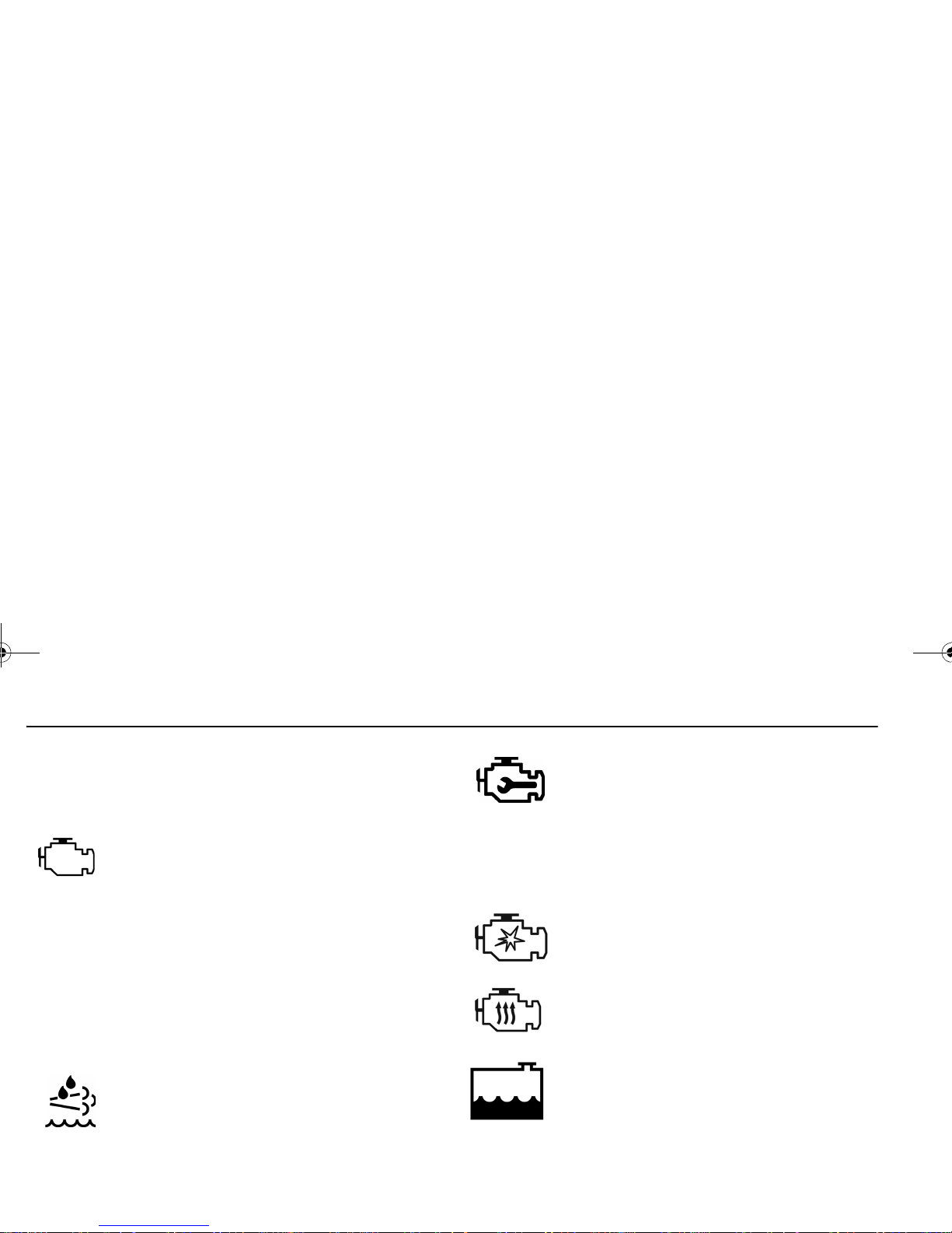
17.Engine, Ether Start
Illuminates when ether start switch is on.
18. Engine, Heater
Illuminates when Engine Heater switch is on.
19. Engine, Low Coolant Level
Illuminates with an audible alarm indicating
critically low coolant level. The vehicle must
be serviced to correct the problem but the situation should not be considered an emergency.
Y53-6032.book Page 26 Monday, May 24, 2010 3:37 PM
PART 4: CONTROLS AND DISPLAYS INSTRUMENTS AND CONTROLS
20. Engine, Overspeed
Illuminates when engine RPM is exceeded.
21. Engine, Retarder (Brake)
Illuminates when the engine retarder (compression brake or exhaust brake) switch is
turned on. (Engine retarders are an option.)
22. Engine, Stop Engine
Illuminates and an audible alarm tone will
sound when a major engine system problem
exists.
WARNING! This should be considered
an emergency. You should stop the vehicle as safely as possible and turn OFF
the ignition. The vehicle must be serviced and the problem corrected before
driving again. Failure to do so may cause
severe engine damage or cause an accident involving death or personal injury.
23. Engine, Wait To Start
Illuminates when engine grid heater is on
(Cummins ISB and ISC engines).
24. Fifth Wheel, King Pin Lock
Illuminates when air actuated fifth wheel King
Pin is unlocked.
25. Fifth Wheel, Slide Unlocked
Illuminates and an audible warning tone will
sound when the air operated sliding fifth
wheel switch is on, thus unlocking the sliding
fifth wheel. The light and an audible warning
tone should NOT be considered an emergency but simply as a reminder to turn off the
switch to lock the sliding fifth wheel before
driving. This switch should not be operated
while driving. (Sliding fifth wheels are an
option).
Y53-6032.book Page 27 Monday, May 24, 2010 3:37 PM
INSTRUMENTS AND CONTROLS PART 4: CONTROLS AND DISPLAYS
26. Lights, High Beam
Illuminates when the high beams are on.
This icon will flash with audible alarm if the
headlamps are left on when the door is open.
In addition, this icon will flash, but without an
audible alarm, if there is a problem with the
low beam headlights or the low beam headlight wiring. In such event, the high beam
headlights will turn on at 50% normal brightness.
27. Message Waiting
Illuminates with telematic equipped messaging.
28. Park Brake
Illuminates in the status indicator when parking brakes are applied and the vehicle is stationary. This symbol will also illuminate in the
Driver Information Display if the parking
brakes are applied and the vehicle is in
29.Power Take-off (PTO)
Illuminates when the PTO is engaged.
NOTE: Do not drive vehicle with PTO
engaged.
30.Power Take-off (PTO), Pump Mode
Illuminates with remote throttle application.
Indicates pump mode is active.
31. Refrigerator
Illuminates to indicate that the refrigerator is
on and ignition is off.
32. Seat Belt, Fasten
Illuminates when the ignition key is turned on
as a reminder to fasten your seat belt.
33.Suspension Dump
Illuminates when suspension air bags are
Y53-6032.book Page 28 Monday, May 24, 2010 3:37 PM
 Loading...