

Page 1
RPK5-GM4101
Complete Radio Replacement Kit with
Integrated Climate Control Retention for
2010-2015 Chevrolet Camaro
Parts List
The RPK5-GM4101 includes everything you need for a professional installation of an aftermarket radio in your Camaro.
This kit contains:
1. Dash Kit
• (x1) PAC HVAC Control Panel (Transfer of the factory HVAC knobs is required. See instructions below)
• (x2) Radio Mounting Brackets (One left and one right)
• (x1) Pocket (For single din applications)
• (x8) Radio Mounting Screws
2. RP5-GM4101 (Camaro specic radio replacement module)
3. Camaro specic antenna adapter (BAA-DIN22).
4. Rear camera retention cable for vehicles equipped with the MyLink system.
5. USB retention cable. This cable is compatible with vehicles equipped with the MyLink radios and vehicles equipped with the
standard non-touchscreen radios. It will require that the cable be ran to the back of the center console.
6. AUX retention cable for 2010-2012 vehicles equipped with the standard non-touchscreen radios also equipped with a USB port.
Overview
The RPK5-GM4101 is a complete radio replacement kit with integrated climate control retention for the 2010-2015 Chevrolet
Camaro. This kit utilizes the factory HVAC control knobs for a more factory look and experience. To add to the factory look
and experience the exterior temperature display is retained by a small OLED display at the top of the kit retaining this valuable
vehicle feature. This kit also includes all of the modules and cables needed to retain all of the important features of the factory
system such as OnStar, factory warning chimes, factory Bluetooth, steering wheel mounted radio controls, factory reverse
camera, factory amplier (if equipped), AM/FM reception, factory AUX jack (if equipped) and the factory USB port (if equipped).
Table of Contents: Page:
1. Factory Radio Removal ------------------------------------------------------ 1-2
2. Disassembly of the factory HVAC control module --------------------- 2-3
3. Assembly of the PAC HVAC control module ---------------------------- 3-4
4. RP5-GM4101 Instructions --------------------------------------------------- 4-6
5. AUX & USB Cable Installation ------------------------------------------------ 7
6. Temperature Display Settings ------------------------------------------------- 7
7. Sub-Dash Preparation ----------------------------------------------------------- 7
8. Kit Assembly Instructions ------------------------------------------------------- 8
9. Installation of the PAC HVAC control module --------------------------- 8-9
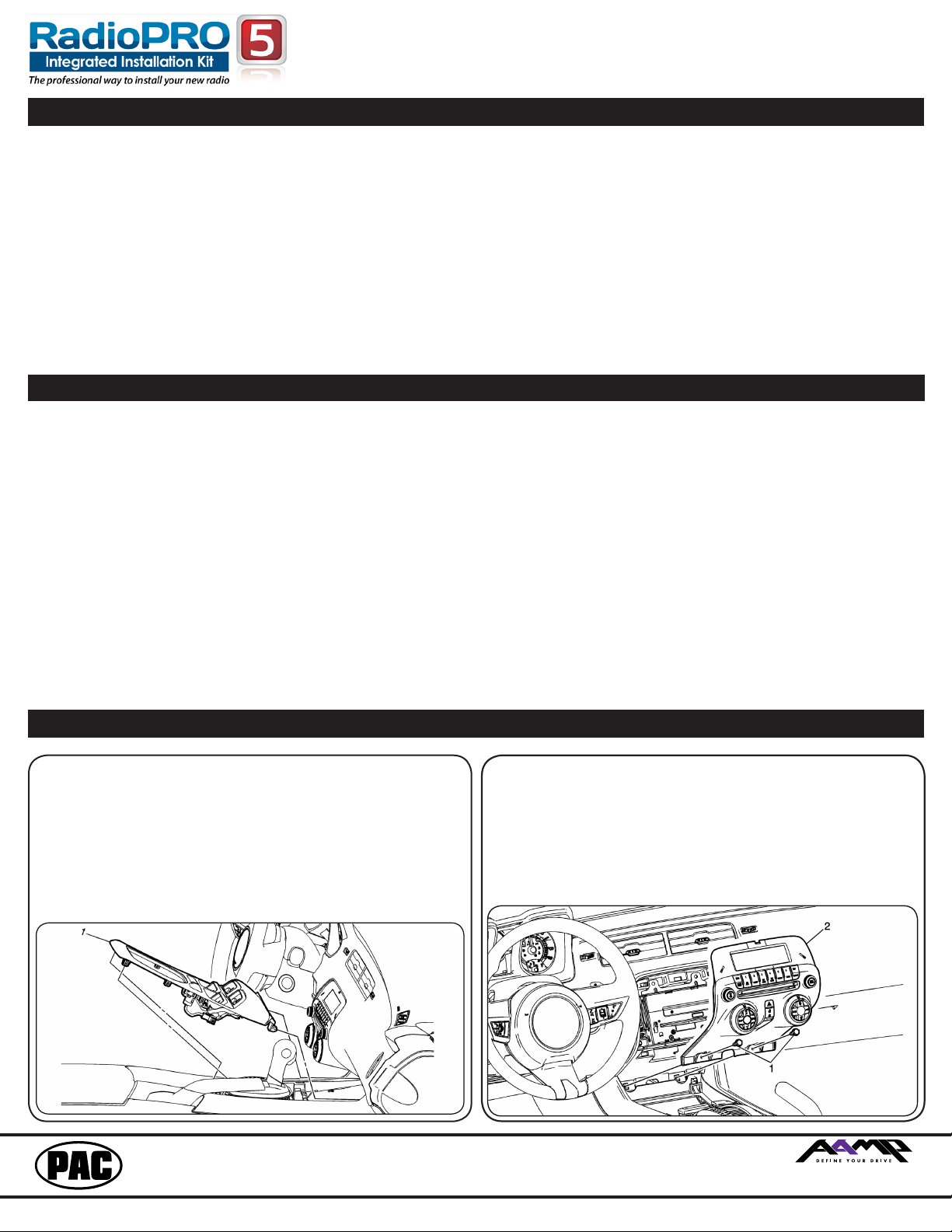
Removing the factory radio from the vehicle
1.1 - Apply the parking brake. Move the transmission shift
assembly to the most rearward position possible. Use a
at bladed plastic trim tool and release the retainer tabs
securing the front oor console front cover to the console
assembly. Lift the cover (1) up and rearward making sure that
the accessory power receptacle and the electronic traction
control switch clears the transmission shift assembly. It may be
necessary to pop them loose from the underside to achieve
clearance. Disconnect the electrical connections.
1.2 - Remove the 2 x 7mm bolts (1) securing the radio
control assembly (2) into the dash. Then use a at-
bladed plastic trim tool in order to release the retainer
clips securing the radio control assembly (2) to the
instrument panel. Disconnect the electrical connections.
PAC® | 866-931-8021 | support@pac-audio.com
©2016 Pacic Accessory Corporation
www.pac-audio.com
PAC is an AAMP power brand
Rev. 113016
Page 2
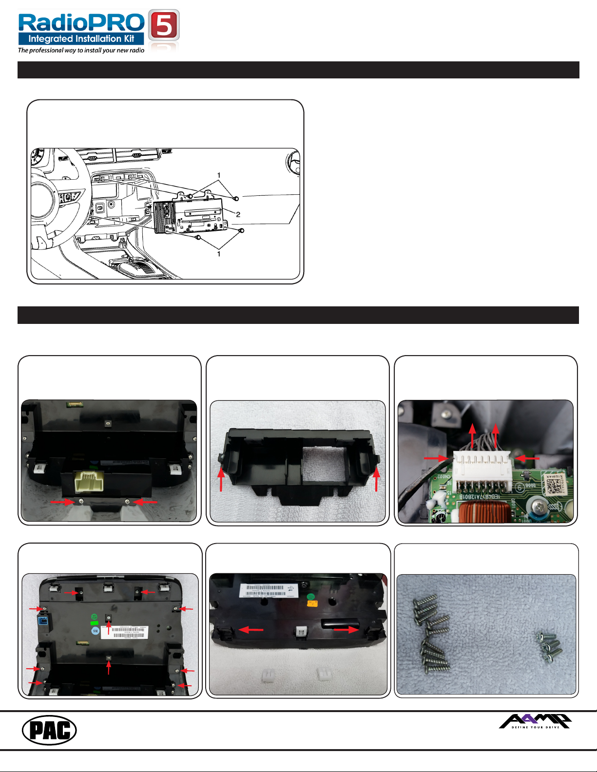
Removing the factory radio from the vehicle (cont.)
1.3 - Remove the 4 x 7mm bolts (1) securing the radio
(2) into the dash. Slide the radio (2) to the rear and
disconnect all electrical connections.
RPK5-GM4101
Complete Radio Replacement Kit with
Integrated Climate Control Retention for
2010-2015 Chevrolet Camaro
You can set the radio aside as it will not be used fur-
ther. For the next section, you will be working with
the factory HVAC control panel to utilize the HVAC
knobs allowing for more of a factory experience
when using the PAC RPK5-GM4101.
Proceed to the next section to begin disassembly of
the factory radio control assembly.
Disassembly of the factory HVAC control panel
The following steps will aide you in the disassembly of the HVAC control panel so that the factory
HVAC control knobs and supports can be reused in the PAC RPK5-GM4101 Integrated Kit.
2.3 - Once the plastic trim is removed, locate
the 16 pin connector shown below. Using a
at bladed tool, press in the grooves on both
sides, pry upward and away from the circuit
board, to release the connector.
2.6 - Be sure to keep the screws
separated as there are different lengths
and diameters.
2.1 - Remove the 2 Phillips head screws
shown below.
2.4 - Remove the 10 Phillips head screws
shown below and remove the black plastic
backing.
2.2 - Pry outwards on the clips on either side
of the plastic trim that surrounds the white
connector.
2.5 - Using a at bladed pry tool remove two
of the white fasteners off of the black plastic
backing.
PAC® | 866-931-8021 | support@pac-audio.com
©2016 Pacic Accessory Corporation
www.pac-audio.com
PAC is an AAMP power brand
Rev. 113016
Page 2
Page 3
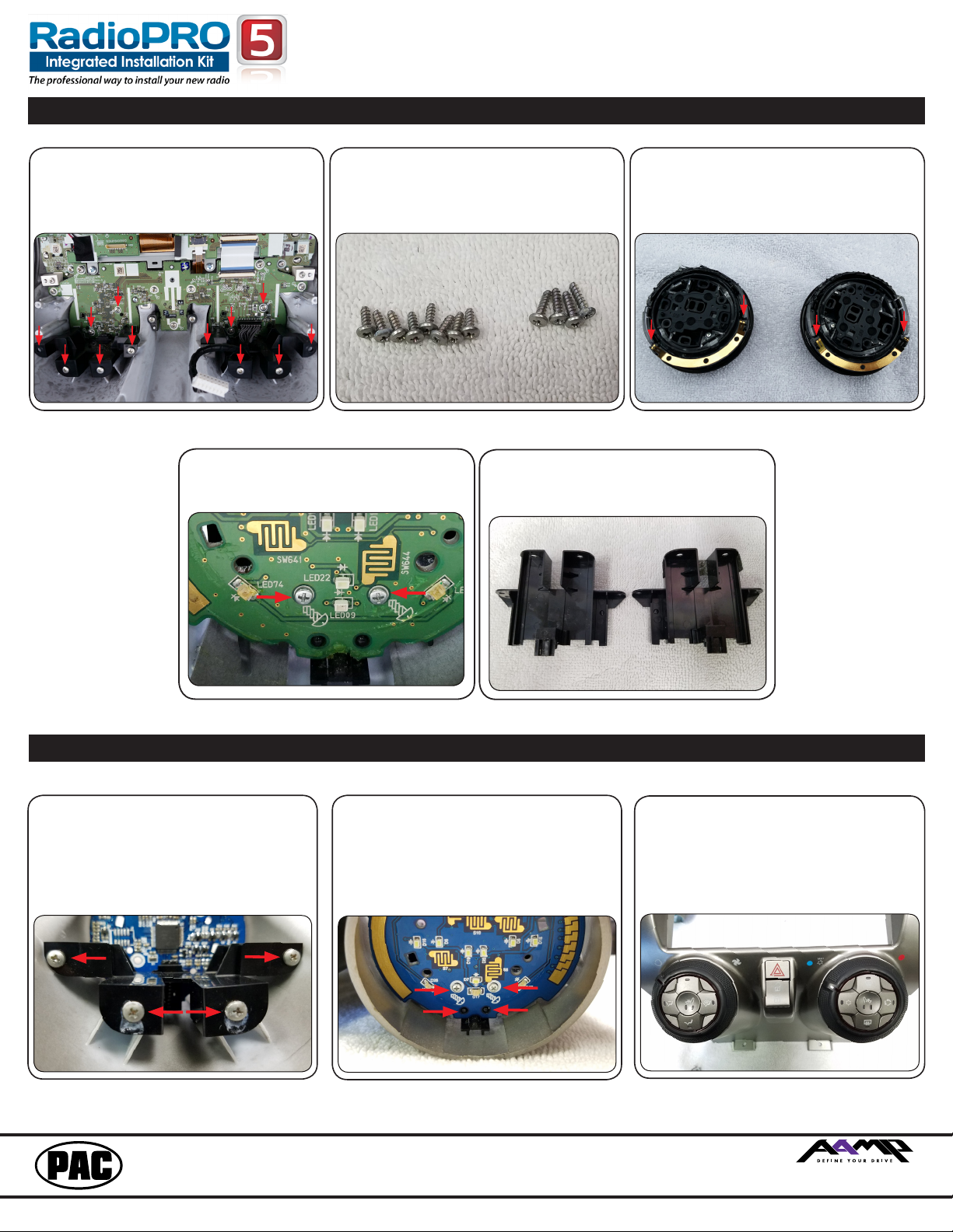
Disassembly of the factory radio control assembly (cont.)
2.7 - Remove the 12 Phillips head screws
shown below.
2.8 - Be sure to keep the screws separated
as they will be used during the assembly
stage later.
RPK5-GM4101
Complete Radio Replacement Kit with
Integrated Climate Control Retention for
2010-2015 Chevrolet Camaro
2.9 - After the screws have been removed,
remove the HVAC knobs by pulling them
from the front of the faceplate being careful
not to bend the contacts on either end of the
contact swiper on the backside of each of
the knobs.
2.10 - Look inside the opening where the
knobs were removed. Remove the 2 Phillips
screws shown below. Do this for both
openings
.
Assembly of the PAC HVAC control assembly
3.1 - Secure the 2 support brackets to the
PAC HVAC control assembly using 4 of the
same screws shown in disassembly step #
7. Do this to the back of each side. Be sure
that the alignment tabs are seated properly
in the circuit board to the front.
3.2 - Secure the 2 support brackets to
the circuit board using the same screws
removed from Disassembly step # 9. The
screws will pass through the board and
thread into the brackets via the holes dened
below. Be sure that the alignment tabs are
2.11 - Remove the 2 support brackets and
keep handy as they will be used in the next
seated properly.
step.
3.3 - Position the knobs in the proper opening
so that the buttons are straight and insert
them into the opening. With VERY LITTLE
force rotate them slightly left and right while
pushing them towards the PCB. Once the
alignment tabs are lined up they should click
and lock into place. Use extra caution as the
contacts could bend while rotating.
PAC® | 866-931-8021 | support@pac-audio.com
©2016 Pacic Accessory Corporation
www.pac-audio.com
PAC is an AAMP power brand
Rev. 113016
Page 4

Assembly of the PAC HVAC control assembly (cont.)
RPK5-GM4101
Complete Radio Replacement Kit with
Integrated Climate Control Retention for
2010-2015 Chevrolet Camaro
3.4 - Secure the knobs to the circuit
board using the same screws shown in
disassembly step # 7. The screws will pass
through the circuit board and thread into the
knobs via the holes dened below.
3.5 - Slide the white fasteners onto the two
black posts at the top of the PAC HVAC
control assembly.
RP5-GM4101 Introduction & Features
The RP5-GM4101 interface allows the replacement of a factory radio in the 2010-2015 Chevrolet Camaro. Using this
interface will retain factory features such as OnStar, Bluetooth, steering wheel controls (SWC), AUX Audio, USB and
warning chimes when the original radio is removed. Use of this interface also allows you to program two radio functions
to each SWC button by using short press long press dual command functionality. The RP5-GM4101 also provides data
bus driven outputs such as retained accessory power (RAP), vehicle speed sensor (VSS), illumination, reverse trigger
and parking brake.
RP5-GM4101 Important Notes
1. Once the radio has been removed, the vehicle settings which are normally selected through the factory radio can be accessed using the
PAC Interface Updating Device (PAC-UP) along with downloading and installing the PAC Vehicle Settings program (for windows PC) from:
http://www.pac-audio.com/rmware/RP/index.html.
2. As in most radio replacements where the car has a separate Bluetooth module it is recommended that the phone(s) be “Unpaired” with the
factory Bluetooth. This way the phone will always pair to the new radio.
3. The Answer/Voice & End/Mute buttons can be set to do the factory OnStar functions or given the ability to control the aftermarket radio. This
option can be found in the PAC Vehicle Settings program mentioned above in note one. The default setting for these buttons is to control the
factory OnStar. If these buttons are set to control the aftermarket radio, OnStar can still be accessed by using the mirror controls.
4. The radio select rotary switch on the side of the interface must be adjusted to the proper radio setting before plugging the interface into the
vehicle (see below for setting chart).
5. The interface comes pre-programmed for all of the vehicles factory SWC functions and does not require programming unless you wish to
re-assign the SWC functions or utilize the short press long press dual command functionality. The SWC can always be restored to default
settings by pressing and releasing the program button on the side of the interface once and waiting 7 seconds for the LED to ash 4 times.
6. The LED will ash whenever a SWC button is pressed.
RP5-GM4101 Wiring Connection Chart
Aftermarket Radio Connections
Yellow Battery +12v
Black Ground
Red Accessory Output
White Front Left + input
White / Black Front Left - input
Grey Front Right + input
Grey / Black Front Right - input
Green Rear Left + input
Green / Black Rear Left - input
Purple Rear Right + input
Purple / Black Rear Right - input
Blue Not Used
Blue / White Amplier Remote Turn
On
Orange / White Illumination Output (+)
Purple / White Reverse Output (+)
PAC® | 866-931-8021 | support@pac-audio.com
Light Green Parking Brake Output (-)
Pink Vehicle Speed Output
Brown Loop Mute Loop - See Note
Installation Step 4 on Page 6
SWC Connector
Blue / Yellow Kenwood, or Newer JVC
3.5mm Jack Alpine, JVC, Clarion,
Pioneer, Sony, Boyo,
Dual, Lightning Audio,
Visteon, Jensen or Advent
©2016 Pacic Accessory Corporation
www.pac-audio.com
Antenna Adapter
Blue
Power Antenna output from
aftermarket radio
RCA Connectors (Main Connector)
Red
White
AUX Audio Retention Right
AUX Audio Retention Left
RCA Connector (Grey connector)
Yellow Reverse Camera
3.5mm Connector (Black connector)
3.5mm Jack AUX retention for 20102012 vehicles equipped
with a factory USB port.
PAC is an AAMP power brand
Rev. 113016
Page 4
Page 5

RP5-GM4101 Illustration / Schematic
SWC Connection
See above chart for
different radio type
connections
x3
AUX AUDIO
CAMERA
V
V
1
2
3
4
5
6
7
8
9
0
RPK5-GM4101
Complete Radio Replacement Kit with
Integrated Climate Control Retention for
2010-2015 Chevrolet Camaro
Vehicle
Connections
Wiring
Aftermarket
Radio
Connections
SWC Connection
RP5-GM4101 Installation Steps
SET RADIO SELECT SWITCH
Alpine JVC Kenwood
Clarion /
Nakamichi
Pioneer/Other Sony Fusion
1 2 3 4 7 8 9
Other = Advent, BOYO, Dual, Jensen, Lightning Audio, Rockford Fosgate & Visteon
1. The radio select rotary switch on the side of the interface must be adjusted to the proper radio setting
before plugging the interface into the vehicle.
2. Make all connections as described in the chart on page 1.
3. Plug the CMX chime module in if necessary (If the vehicle chimes when the radio is removed the CMX is not necessary). PLEASE NOTE:
In order to get the best possible sound out of the CMX please mount it in a place free and clear of any obstructions, preferably as close as
possible to the bottom of the dash pointing down toward the oor of the vehicle.
4. The Mute loop (if not cut) will turn the accessory output off when an OnStar or Bluetooth call is made or received. If the aftermarket radio
has a mute input cut this loop and connect the outer brown wire to the mute input.
5. Connect the SWC wire according to the chart on page 5 (aftermarket radio MUST support a wired remote input).
6. If you wish to reassign functions to the SWC follow the programming instructions in the next section.
7. Connect the proper AUX cables depending if your vehicle has the MyLink or standard non-touchscreen radios equipped with a USB port.
8. Connect the supplied USB retention cable. MyLink radios will have a mini USB cable behind the radio. In this case the USB-GM1 cable (sold
separately) can be used. The supplied cable will need to be ran to the back of the factory USB port located at the rear of the center console.
RP5-GM4101 Default Steering Wheel Control Programming
IMPORTANT!
wish to re-assign the SWC functions or utilize short press long press dual command functionality. The SWC can always be restored to default
settings by pressing the program button on the side of the interface once and waiting for the timeout.
The Mute/End button has two functions. Pressing this button for less than 1.5 seconds will initiate the mute command. Pressing this button for
more than 1.5 seconds will initiate the end command. This dual function button can also be reprogrammed to whatever features the customer
chooses.
Default SWC Button Assignments
The interface comes pre-programmed for the functions listed in the chart below and does not require programming unless you
olume +
olume Source
Track +
Track -
Answer/Voice
Mute/End
Alpine JVC Kenwood
Volume + Volume + Volume + Volume + Volume + Volume + Volume +
Volume - Volume - Volume - Volume - Volume - Volume - Volume Source Source Source Source Source Source Source
Track + Track + Track + Search + Track + Track + Track +
Track - Track - Track - Search - Track - Track - Track -
Answer/OnStar
Activation
Mute/Factory
Bluetooth End
Answer/OnStar
Activation
Mute/Factory
Bluetooth End
PAC® | 866-931-8021 | support@pac-audio.com
Answer/OnStar
Activation
Mute/Factory
Bluetooth End
©2016 Pacic Accessory Corporation
www.pac-audio.com
Clarion/
Nakamichi
Answer/OnStar
Activation
Mute/Factory
Bluetooth End
Pioneer Sony Fusion
Answer/OnStar
Activation
Mute/Factory
Bluetooth End
Answer/OnStar
Activation
Mute/Factory
Bluetooth End
Answer/OnStar
Activation
Mute/Factory
Bluetooth End
PAC is an AAMP power brand
Rev. 113016
Page 6

RPK5-GM4101
Alpine JVC Kenwood Clarion / Nakamichi
Other
Pioneer Sony Fusion
1 Volume + Volume + Volume + Volume + Volume + Volume + Volume + Volume +
2 Volume - Volume - Volume - Volume - Volume - Volume - Volume - Volume -
3 Mute Mute Mute Mute Mute Mute Mute Mute
4 Preset + Source Source Source Preset + Preset + Preset + Source
5 Preset - Track + Play Search + Preset - Preset - Preset - Track +
6 Source Track - Track + Search - Source Source Source Track 7 Track + Band/Disc + Track - Band Track + Track + Track + Audio
8 Track - Preset/Disc - Disc/FM + Send/End Track - Track - Track - Power
9 Power Select Disc/AM - Send Band Band Band
10 Enter/Play Attenuation Answer End
Answer
Phone Menu
Reject Call/Source
(Bluetooth equipped
radios only)
11 Band/Program Phone Receive Voice Dial
END
Answer Call Answer/End Call
12 Receive Phone Reject On Hook
PTT
End Call
13 End Voice Dial Off Hook VR
14 VR Power
Mute (Multimedia
units only)
15 Preset +
- Advent, Boyo, Dual, Lightning Audio, Jensen, Rockford Fosgate & Visteon - Jensen & Advent ONLY
Complete Radio Replacement Kit with
Integrated Climate Control Retention for
2010-2015 Chevrolet Camaro
RP5-GM4101 Optional Steering Wheel Control Programming
If you wish to re-assign the SWC functions or utilize short press long press dual command functionality, the interface must be programmed in the
specic order shown in the chart below. If you come across a function in the chart that your steering wheel does not have, or you do not want
to program, press and release the program button on the side of the interface to skip that function. The LED will ash off and on conrming that
you have successfully skipped that function and are ready to proceed to the next one.
Short Press Long Press Dual Command Functionality
This feature allows you to assign two aftermarket radio functions to each of the vehicle’s SWC buttons. It can be used with as many of the
buttons as the user likes or none at all. When this functionality is implemented, quickly pressing and releasing a SWC button will initiate the short
press command, while pressing and holding a SWC button for longer than two seconds will initiate the long press command. Please note that
all buttons except the Mute button do not have a long press command programmed by default. If you wish to assign dual command functionality
to the SWC please follow the programming steps on the next page.
Optional Programming Order
Programming the SWC assignments
1. Turn the key to the ignition position.
2. Press and release the programming button on the side of the interface. The SWC LED will turn on solid.
3. Within 7 seconds, press the button that is to be learned on the steering wheel. The SWC LED will turn off when the button is pressed. At
this point you have two options:
A. For short press functionality: Release the button within 1.5 seconds. The SWC LED will turn back on.
B. For long press functionality: Hold the button until the SWC LED starts blinking. Release the button and the SWC LED will go
back to solid.
4. If you need to program more buttons, repeat step 3 for each additional audio function on the steering wheel.
5. If you come across a function in the chart that your steering wheel does not have, or you do not want to program, press and release the
program button on the side of the interface to skip that function.
6. Once programming is completed, wait seven seconds. The SWC LED will ash three times indicating end of programming.
7. Test the interface for proper functionality. Whenever a SWC is pressed the SWC LED on the interface should blink. If any function does
not work, repeat the programming steps.
RP5-GM4101 Testing & Verication
1. Turn the ignition on. The LED on the interface will turn on & the +12v accessory wire will turn on.
2. Turn on the radio and check balance & fade.
3. Verify that all SWC are functioning properly for both the aftermarket radio and OnStar. To adjust OnStar volume, press the
OnStar button on the mirror then use the volume buttons on the SWC to adjust the level. The volume will raise a total of 8
times before returning to the original level.
4. Pressing the OnStar® button on the rearview mirror will turn off the rear speakers and allow the OnStar® audio to be heard
in the two front speakers. The OnStar® active LED will also turn on. When OnStar® disconnects, the radio will un-mute or
turn back on and the OnStar® LED will turn off. Pressing the Mute/OnStar® button on the steering wheel for 1.5 seconds
will also activate Onstar®.
5. Turn off vehicle and remove key. RAP will be active and keep the radio on for 10 minutes, or until the driver’s door is opened.
6. The Accessory LED and radio will turn off when RAP turns off or the driver’s door is opened.
RP5-GM4101 Product Updates (Firmware)
The RP5-GM4101 can be updated with new rmware as it becomes available using the PAC-UP interface updater (sold separately).
Please visit www.pac-audio.com/rmware for available updates.
PAC® | 866-931-8021 | support@pac-audio.com
©2016 Pacic Accessory Corporation
www.pac-audio.com
PAC is an AAMP power brand
Rev. 113016
Page 6
Page 7

USB and AUX cable Installation
1. Use a at bladed plastic trim tool and release the retainer clips
securing the console’s (1) right & (2) left side covers to the front
oor console assembly.
2. Move the front seats to the forward most position.
3. Remove the 4 Phillips head bolts (3) securing the consoles rear
cover (4) to the front oor console.
4. Remove the front oor console rear cover (4).
5. Remove the electrical connections from the back of the AUX and
USB panel located inside the center console.
6. Connect the RPK5-GM4101-AUX-HAR and the RPK5-GM4101 USB-HAR (if the vehicle is equipped with factory AUX).
7. Route the new AUX and USB cables down the driver side and
using a sh tape, route the cables up into the radio cavity.
Sub-Dash Preparation
RPK5-GM4101
Complete Radio Replacement Kit with
Integrated Climate Control Retention for
2010-2015 Chevrolet Camaro
1. Locate the radio brain alignment tabs. Each
side needs to be trimmed for clearance of the new
HVAC panel
Note: Some radios will require extra
depth during installation. If you
encounter this issue please follow the
next two steps to modify the dash for
extra clearance.
***Warning: Check for factory wiring
harnesses around (including behind)
this area before cutting. Use caution
not to cut any of this wiring
2.
Remove the conical portion of the
1. Locate the factory radio module mounting hole
towards the back of the dash opening.
alignment tab.
3.
When nished, the tabs should look like the
2.
Cut and remove the portion that extends
towards the front dash opening.
one below.
Kit Assembly Instructions (Single DIN)
Single DIN Mount Applications
1. Snap and lock each of the side brackets onto the pocket. FIG 1
2. Insert ISO mountable radio between the side mount brackets and loosely attach to
sides of radio using screws provided with radio when possible or hardware included
with kit.
3. Slide radio component forward or backward for desired look and tighten screws.
4. Attach a rear support bracket to the rear of the new radio and adjust as necessary to
attach to the rear support stud located on the back of the pocket using the small
phillips screw supplied with kit (optional).
5. Insert kit and radio into dash. Line up with the factory mounting point. Secure to the
dash using the factory 7mm bolts.
PAC® | 866-931-8021 | support@pac-audio.com
©2016 Pacic Accessory Corporation
www.pac-audio.com
FIG 1
PAC is an AAMP power brand
Rev. 113016
Page 8

RPK5-GM4101
Complete Radio Replacement Kit with
Integrated Climate Control Retention for
2010-2015 Chevrolet Camaro
Kit Assembly Instructions (Double DIN)
Double DIN Mount Applications
1. Remove the Shaded tab from the back edge of each left and right mounting bracket (right side not shown). FIG 2
2. Attach the left and right side brackets to an ISO mountable radio using screws provided with radio when possible or hardware
included with kit. FIG 3
3. Insert kit and radio into dash. Line up with the factory mounting point. Secure to the dash using the factory 7mm bolts.
FIG 2
FIG 3
Installation of the PAC HVAC control panel
Vehicles equipped with Non-MyLink radios
1. Connect the RPK5-GM4101-KIT-HAR to the vehicles white 20 pin connector that was originally connected to the factory HVAC
control panel.
2. Connect the 8 pin Black Micro-t Molex connector to the circuit board mounted to the back side of the PAC HVAC control
module.
3. Tape up or remove the loose Orange / Black and Pink / Black wires as they are only needed for applications where the vehicle
was factory equipped with the touchscreen MyLink radio.
4. Fit the PAC HVAC control panel into the vehicle opening and secure at the bottom using the factory mounting hardware.
5 . Assemble the remaining pieces of the dash.
Installation of the PAC HVAC control panel (cont.)
Vehicles equipped with MyLink radio
1. Connect the RPK5-GM4101-KIT-HAR to the vehicles white 20 pin connector that was originally connected to the factory HVAC
control panel.
2. Connect the 8 pin Black Micro-t Molex connector to the circuit board mounted to the back side of the PAC HVAC control
module.
3. Locate the Orange/Black (Pin 15) and Pink/Black (Pin 19) wires in the 27 Pin Lt. Blue connector at the Body Control Module
(BCM). The BCM is located under the driver side of the dash.
4. Connect the loose end of the Orange / Black extension wire to the Orange/Black wire in Pin 15.
5. Connect the loose end of the Pink / Black extension wire to the Pink/Black wire in Pin 19.
6. Route both of the extension wires to the right and through the same opening that the White 20 pin connector passes through
and connect them to the bullet connectors on the RPK5-GM4101-HIT-HAR. Be sure to not route these wires near any moving
parts as it could cause damage to these wires in the event they become pinched.
** If the kit mounted door lock buttons operate in reverse after connection of these wires, then the Orange / Black wire
and Pink / Black have been connected in reverse. To x, reverse the connections at the wires or simply swap the wires at the
bullet connectors**
7. Fit the PAC HVAC control panel into the vehicle opening and secure at the bottom using the factory mounting hardware.
8. Assemble the remaining pieces of the dash.
Picture of the BCM which is located under the driver side of the
dash just above the steering column
PAC® | 866-931-8021 | support@pac-audio.com
©2016 Pacic Accessory Corporation
www.pac-audio.com
Close up of the Light Blue
connector located at the BCM
PAC is an AAMP power brand
Rev. 113016
Page 8
Page 9

RPK5-GM4101
Complete Radio Replacement Kit with
Integrated Climate Control Retention for
2010-2015 Chevrolet Camaro
PAC HVAC Control Panel Testing and Verication
1. Turn the ignition on. The LCD at the top of the kit should come on and display the temperature.
2. Verify functionality of the lock, unlock and hazard buttons.
3. Verify functionality of the rotary dials and all of the push buttons on each of HVAC knobs.
4. For double DIN applications equipped with a 7” screen, verify that the face of the radio does not come in contact with the kit
when ejecting a disk. If it does you will need to adjust placement of the double DIN radio in the mounting brackets.
5. Verify the LED backlights dim when using the factory dimmer control.
6. Verify that the kit, including the temperature LCD, shuts off when the key is turned to the off position.
Temperature Display Settings and Operation
The temperature display is a multifunction display which will display the temperature, the rmware version number and
allow you to change between the preloaded splash screen options.
Switching between Fahrenheit and Celsius:
Press and hold the A/C (snowake) button for 5 seconds to switch the temperature display at the top of the kit between Celsius
and Fahrenheit. Pressing and holding the A/C (snowake) button again for 5 seconds will switch it back. The Kit will default to
Fahrenheit upon rst power up or upon a power cycle (remove and apply power to kit).
Displaying the Firmware Version of the PAC HVAC Control Panel:
Press and hold the recirculation button for 5 seconds to display the rmware version of the PAC HVAC control panel.
Changing the Splash Screen:
Press and hold the rear defrost button for 5 seconds to change the splash screen that is shown when the kit powers up. Each time
the button is pressed and held for 5 seconds it will advance to the next splash screen. Once the splash screen has changed you
will need to release the button and press and hold it for 5 seconds for it to change again. For the order in which the splash screens
will change when the button is held, see below:
PAC® | 866-931-8021 | support@pac-audio.com
©2016 Pacic Accessory Corporation
www.pac-audio.com
PAC is an AAMP power brand
Rev. 113016
 Loading...