

Page 1

RPK4-CH4101
Integrated Climate Control Retention for Select
2013-2019 RAM Trucks
Introduction and Features
Complete Radio Replacement with
The RPK4-CH4101 is a complete radio replacement kit with integrated climate control retention for the 2013-2019 RAM
trucks equipped with the 8” screen. All modules and cables are included to retain important features of the factory
system including: steering wheel mounted radio controls, factory reverse camera, and AM/FM reception.
A secondary 5.2” LCD screen is added for additional vehicle control including: Climate Controls user interface retention,
vehicle settings retention, factory amplier control, settings for control of the RPK4.2-CH4101 interface, forced camera
activation, ability to add additional cameras, tire pressure and vehicle gauges. Features provided by the LCD screen
will vary based on the vehicle features. See Important Notes (next section) for additional information.
Four hard buttons added to the radio dash bezel (below the 5.2” LCD screen) allow user to set presets to control
functions including: specic climate controls, forced camera activation, LCD screen controls. Options for hard
buttons will vary based on vehicle features and which cameras are installed.
Some advanced features require additional accessories, sold separately.
Important Notes
We recommend reading this manual thoroughly to familiarize yourself with the entire process
prior to beginning the installation.
1. Only compatible in vehicles equipped with the 8” screen.
2. 2019 RAM Trucks: Only compatible with Classic body style.
3. Does Not Retain:
• Cluster Display Features
• Compass
• Clock
• Phone pop-ups
• Navigation pop-ups
4. In trucks equipped with parking sensors you must use the included external speaker in order to continue hearing parking
sensor chimes. If the truck has a factory amplied system and parking sensors, the speaker is not necessary unless the
factory amplier is no longer being used.
5. If you are adding additional cameras, or the truck has additional factory cameras beyond reverse cam, PAC part
number RPA-16P5V (sold separately) must be used to connect up to 5 total cameras.
• uConnect Features
• WiFi-Hotspot
• SOS / Assist
• Factory Amplier Features
• Speed Controlled Volume
© 2019 AAMP Global. All rights reserved. PAC is a Power Brand of AAMP Global.
PAC-audio.com
Rev: V1
Date:122019
Page 1
Page 2
RPK4-CH4101
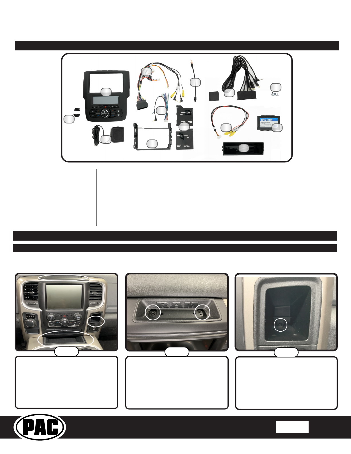
Components
Complete Radio Replacement with
Integrated Climate Control Retention for Select
2013-2019 RAM Trucks
4
2
1
3
Tools needed for installation:
Phillips head screwdriver,
7mm socket, ratchet, T20 torx
screwdriver, plastic panel removal
tool (example - PAC part number
TL-PRY2), airsaw or hacksaw with
metal cutting blade (unless you are
installing a shallow mount radio;
details on page 6).
1. Climate Control Button Inserts
2. Radio Dash Bezel with 5.2” LCD Display
3. External Chime Speaker
4. RP4.2-CH4101 Interface Harness
5. RP4.2-CH4101 Aftermarket Radio
6. Radio Mounting Shroud
7. AM / FM Antenna Adapter (BAA22)
*Some kits include a USBDMA6 and instructions for how to obtain a USB Hub Replacement.
Installation
Part One: Disassembly of Factory Dash
5
6
Connection Harness
7
9
8
10
11
8. Radio Mounting Brackets
9. OEM USB Replacement Hub*
10. Reverse Camera Retention Harness
(RPA-16P1V)
11. Single DIN Mounting Pocket
12. Radio Mounting Screws
13. RP4.2-CH4101 Radio Replacement
Interface
12
13
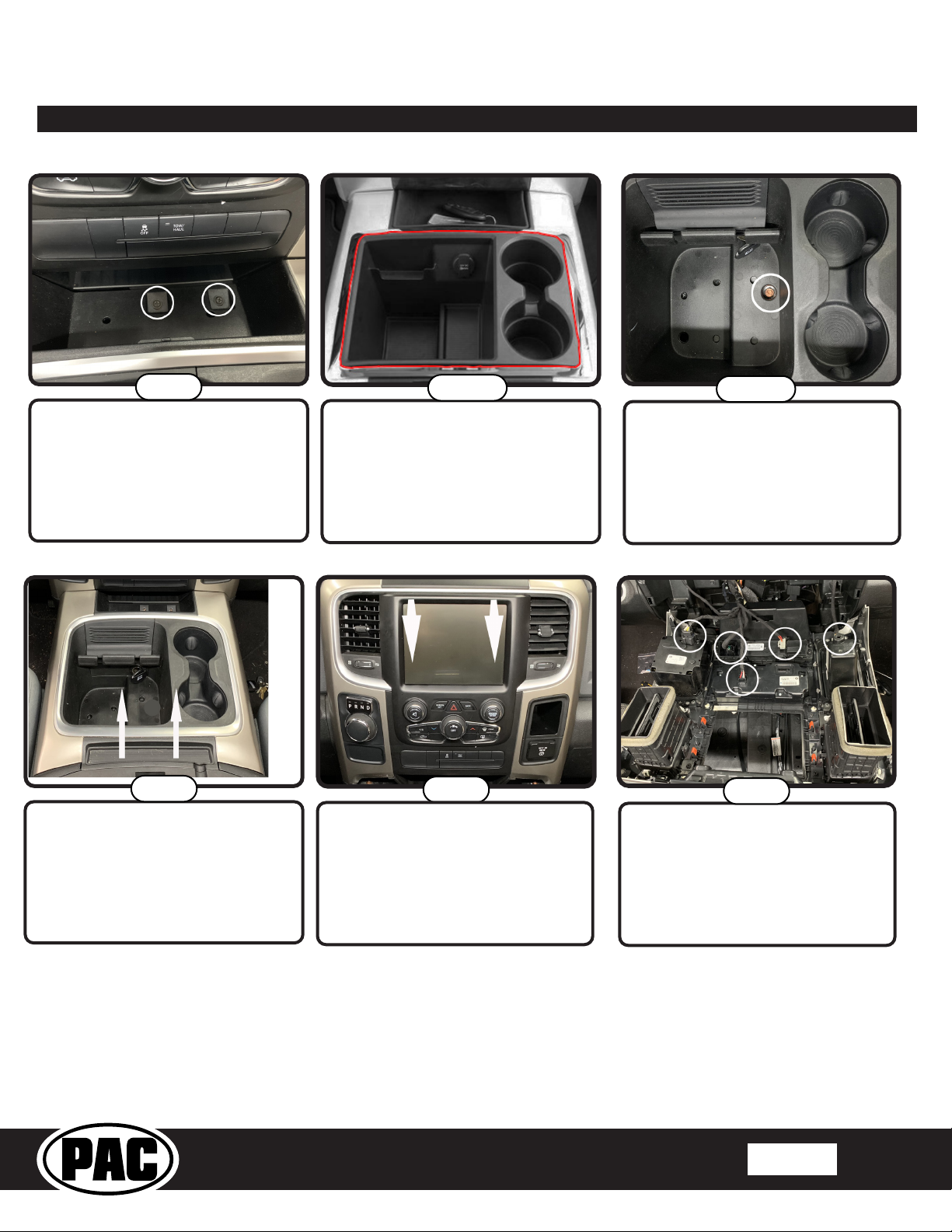
If your truck has a center console, begin here. If not, skip ahead to page 4
Step 1
Remove the circled rubber inserts to
gain access to the screws securing
the dash and console in place.
© 2019 AAMP Global. All rights reserved. PAC is a Power Brand of AAMP Global.
Trucks With a Center Console
Step 2
Remove the two T-20 torx screws
from the top of the dash.
PAC-audio.com
Step 3
Remove the T-20 torx screw from the
back of the small pocket on the right
side of the dash.
Rev: V1
Date:122019
Page 2
Page 3
RPK4-CH4101
Part One: Disassembly of Factory Dash (cont.)
Complete Radio Replacement with
Integrated Climate Control Retention for Select
2013-2019 RAM Trucks
Step 4
Remove the two phillips head screws
in the tray at the bottom of the dash
panel.
Step 6
Remove the center console by pulling
straight up from the back then pulling
the console outward toward the back
of the truck.
Step 5a
2013-2015 models: Remove the
chrome trim ring around the center
console storage compartment.
Step 7
Remove the dash panel by gripping
rmly and pulling straight out on the
top portion of the panel.
Step 5b
2016-2019 models: Remove the
rubber insert in the bottom of the
center console storage compartment.
Remove the 7mm screw from the
bottom of the storage compartment.
Step 8
Disconnect the harnesses from the
back of the dash panel. Once all
harnesses have been disconnected,
remove the dash panel from the
truck.
© 2019 AAMP Global. All rights reserved. PAC is a Power Brand of AAMP Global.
PAC-audio.com
Rev: V1
Date:122019
Page 3
Page 4
RPK4-CH4101
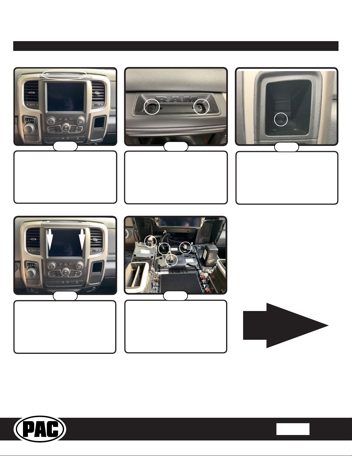
Part One: Disassembly of Factory Dash (cont.)
Trucks Without a Center Console
Complete Radio Replacement with
Integrated Climate Control Retention for Select
2013-2019 RAM Trucks
Step 1
Remove the circled rubber insert to
gain access to the screws securing
the dash in place.
Step 4
Remove the dash panel by gripping
rmly and pulling straight out on the
top portion of the panel.
Step 2
Remove the two T-20 torx screws
from the top of the dash.
Step 5
Disconnect the harnesses from the
back of the dash panel. Once all
harnesses have been disconnected,
you can remove the dash panel from
the truck.
Step 3
Remove the T-20 torx screw from the
back of the small pocket on the right
side of the dash (not always present).
This is the end of
part one. Please
continue to the next
page to begin part
two.
© 2019 AAMP Global. All rights reserved. PAC is a Power Brand of AAMP Global.
PAC-audio.com
Rev: V1
Date:122019
Page 4
Page 5
RPK4-CH4101
Part Two: Radio removal / Dash preparation
Complete Radio Replacement with
Integrated Climate Control Retention for Select
2013-2019 RAM Trucks
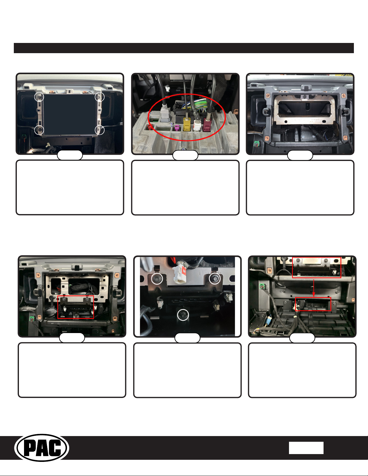
Removing the Radio
Step 1
Remove the four 7mm screws
securing the radio in place.
(If present, not necessary if installing a shallow mount radio)
Step 2
Disconnect the 52-pin dock and lock
connector and all of the antennas
from the radio (the number of
antenna connections will vary based
on the vehicle’s available features).
Relocating the Factory Security Module
Step 3
Remove the radio from the dash
(dash appearance may vary
according to model year).
Step 1
If your truck is equipped with the
factory security module shown here,
it is necessary to relocate the module
to allow for the removal of the lower
portion of the metal support bracket.
© 2019 AAMP Global. All rights reserved. PAC is a Power Brand of AAMP Global.
Step 2
Remove the three 7 mm screws
circled here and set aside.
PAC-audio.com
Step 3
Relocate the security module to
just below the plastic support beam
shown here.
Rev: V1
Date:122019
Page 5
Page 6
RPK4-CH4101
Part Two: Radio removal / Dash preparation (cont.)
Cutting the Sub-Dash
(Not necessary if installing a shallow mount radio)
Complete Radio Replacement with
Integrated Climate Control Retention for Select
2013-2019 RAM Trucks
Step 1
Cut here in 2013-2017 model years.
Step 2
Cut here in 2018-2019 model years.
It is necessary to cut more metal out
of these models.
This is the end of
part two. Please
continue to the next
page to begin part
three.
Step 3
After cutting, the sub dash should
look similar to this.
© 2019 AAMP Global. All rights reserved. PAC is a Power Brand of AAMP Global.
PAC-audio.com
Rev: V1
Date:122019
Page 6
Page 7

RPK4-CH4101
Part Three: Installing the New Dash Panel
Complete Radio Replacement with
Integrated Climate Control Retention for Select
2013-2019 RAM Trucks
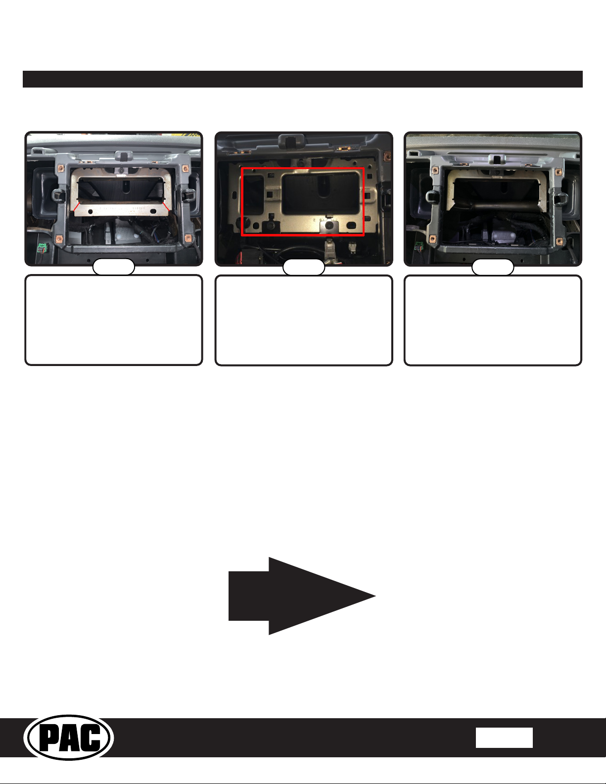
Step 1
Now we are going to remove
the portion of the dash outlined
in red and replace it with the
new PAC dash bezel.
Step 4
Your dash panel should now
look like this. You should also
have 13 phillips head screws
retained from step 2.
Step 2
Remove the 13 phillips head screws
holding the dash bezel onto the dash
panel. Retain these screws as they
will be used to secure the new dash
bezel into the dash panel.
Step 5
Next you must install the
appropriate insert (Auto or
Blank) in the middle of the
fan speed knob on the new
dash panel. Please be sure
to choose the proper insert
as changing them out after
one has been inserted can be
challenging.
Step 3
To remove the factory dash bezel, ip
the panel back over and pull straight
out at the bottom of the bezel, then
down.
Step 6a
If you have Automatic Climate
Controls, install the insert that says
“Auto”. Be sure to line up the light
pipe with the hole in the kit. Please
note that if your truck did not have
automatic climate controls with the
factory panel, inserting this button will
not add that functionality.
© 2019 AAMP Global. All rights reserved. PAC is a Power Brand of AAMP Global.
PAC-audio.com
Rev: V1
Date:122019
Page 7
Page 8

RPK4-CH4101
Part Three: Installing the New Dash Panel (cont.)
Complete Radio Replacement with
Integrated Climate Control Retention for Select
2013-2019 RAM Trucks
Step 6b
The insert should look like this when
installed properly.
Step 8
Now secure the new dash bezel into
place by reinstalling the 13 phillips
head screws removed in step 2.
Step 6c
If you do not have auto AC then
install the blank insert. The insert
should look like this when installed
properly.
Step 9
Your dash should now look like this.
Step 7
Insert the new dash bezel by placing
the top in rst then sliding it up into
place.
This is the end of
part three. Please
continue to the next
page to begin part
four.
© 2019 AAMP Global. All rights reserved. PAC is a Power Brand of AAMP Global.
PAC-audio.com
Rev: V1
Date:122019
Page 8
Page 9

RPK4-CH4101
Mounting the Aftermarket Radio
Double-DIN
Complete Radio Replacement with
Integrated Climate Control Retention for Select
2013-2019 RAM Trucks
Single-DIN
Part Four: Conguring and Wiring the RadioPRO Interface
RP4.2-CH4101 Module Layout
Rotary Dial
Not Used
Interface
Connector 4
Reset Button
Radio Select
DIP switches
USB Port
Interface
Connector 1
LCD Display
Connector Port
Interface
Connector 2
Non-Amplied
Audio Output
Interface Connector 3
LED 2
LED 1
Amplied
Audio Output
Interface Connector 3
© 2019 AAMP Global. All rights reserved. PAC is a Power Brand of AAMP Global.
PAC-audio.com
Rev: V1
Date:122019
Page 9
Page 10

RPK4-CH4101
Integrated Climate Control Retention for Select
Part Four: Conguring and Wiring the RadioPRO Interface (cont.)
Connectors
Complete Radio Replacement with
2013-2019 RAM Trucks
Interface Connector 1
Red Accessory Output
Yellow 12v+
Black Ground
(10A)
Vehicle Connector 1
Yellow Battery +12v
Black Ground
Pink MS-CAN +
Pink / Black MS-CAN -
White / Red HS-CAN+
White / Black HS-CAN-
White Front L + input
White / Black Front L - input
Gray Front R + input
Gray / Black Front R - input
Green Rear L + input
Green / Black Rear L - input
Purple Rear R + input
Purple / Black Rear R - input
Reverse Camera Video from factory reverse
Cargo Camera /
RSE Video
RSE Audio Not Used
OEM AUX Audio Audio from factory Auxiliary
camera
Video from factory cargo
camera
Input Jack
Interface Connector 2
White / Red HS-CAN + Input
White / Black HS-CAN - Input
Pink MS-CAN + Input
Pink / Black MS-CAN - Input
Blue / White Not Used
LCD Display Output Connector
Interface Connector 3
White Front L + output
White / Black Front L - output
Gray Front R + output
Gray / Black Front R - output
Green Rear L + output
Green / Black Rear L - output
Purple Rear R + output
Purple / Black Rear R - output
Ext Speaker
Out
Connect to supplied
external speaker
when installing this
kit into a vehicle that
has factory parking
sensors
Interface Connector 4
Purple Rear R + input
Purple / Black Rear R - input
Green Rear L + input
Green / Black Rear L - input
Gray Front R + input
Gray / Black Front R - input
White Front L + input
White / Black Front L - input
Blue / Yellow SWC Output / Key 1
Brown SWC Output / Key 2
3.5 mm Jack SWC Output
Pink Vehicle Speed
Light Green Parking Brake
Violet / White Reverse Signal
Orange / White Illumination Output
Blue / White Amp Turn On Input
Blue Not Used
Reverse Camera
Retention Harness
Red Aftermarket
Black Aftermarket
Yellow
Composite
Male
Yellow
Composite
Female
Camera Acc 12v+
Output (800 mA)
Camera Ground
Output
Camera Out
To Aftermarket
Radio
Camera In
From Vehicle
Connector
Sense Output
Output
Output
DIP Switches
The radio select DIP switches on the side of the interface must be adjusted to the proper radio setting
Set DIP switches that correspond with your radio to the ON position.
Set all other DIP switches to the OFF position.
Alpine JVC
Kenwood /
Lightning Audio
Clarion /
Nakamichi
/ Stinger
2-Wire
Resistive
Pioneer /
Other*
Sony Fusion
1 2 1 & 2 3 2 & 3 1, 2, & 3 4 1 & 4
*Other - Dual / Axxera (these brands could also have 2-wire resistive), Jensen, Rockford Fosgate
before plugging the interface into the vehicle.
© 2019 AAMP Global. All rights reserved. PAC is a Power Brand of AAMP Global.
PAC-audio.com
Rev: V1
Date:122019
Page 10
Page 11

RPK4-CH4101
To aftermarket radio’s
camera input
RPA-16P1V V1
V Out
V - 5
Video Output
Video Input1
Red - Camera 12v Out (800mA)
Black - Camera Ground Out
From Reverse Camera
To aftermarket reverse camera’s
power wires
4
21 3
Wiring Connections
Complete Radio Replacement with
Integrated Climate Control Retention for Select
2013-2019 RAM Trucks
1. Set the DIP Switches on the side of the interface according to the chart on page
Fig.1: Rear of RPK4-CH4101 Radio
Dash Bezel
10.
2. Wire the aftermarket radio harness according to the wiring connection charts for
Interface Connector 1 and Interface Connector 4 provided on page 10.
3. Connect Interface Connectors 1, 2 and 4 to the RP4.2-CH4101.
4. Connect Interface Connector 3 to either the amplied or non-amplied audio
output connector depending on your scenario.
5. Connect one end of the supplied LCD Display connector into the Expansion Port
on the RP4.2-CH4101 and run the other end to be accessible when re-installing
the factory dash panel.
6. If you are installing this kit into a truck with factory parking sensors and it IS NOT
equipped with a factory amplier, or if the factory amplier is being bypassed,
connect the supplied external chime speaker to the external speaker output on
interface connector 3. Mount in a place free of obstructions so that the parking
sensor chimes can be heard.
7. Connect the SWC output wire to the aftermarket radio (aftermarket radio must
support a wired remote input).
8. Once all connections have been made, plug the vehicle connectors into the
vehicle harness.
9. Reverse camera connection (see Fig. 2):
Connector Connector Function
1
2 Expansion Port (Not Currently Used)
3 Camera Input / Output
4 Climate Control Display USB
RP4.2-CH4101 Display Connector
Update Port
a. Connect the included RPA-16P1V harness to the 16-pin connector
(Connector 3) on the back of the radio dash bezel (see Fig.1).
b. Connect the Male Yellow RCA (Video Output) from the RPA-16P1V harness to the aftermarket radio’s reverse camera
input.
Fig.2: RPA-16P1V Harness
c. Connect the Female Yellow RCA (Video Input) from the RPA-16P1V harness to the Male Yellow RCA from vehicle connector
1 (factory reverse camera), or to the aftermarket reverse camera’s RCA video output.
d. Connect the red and black power wires from the RPA-16P1V to the aftermarket reverse camera’s power wires. If you are
utilizing a factory camera, simply insulate these wires.
e. To Add Additional Cameras (Front, Blind Spot, Cargo, etc.): use the RPA-16P5V (sold separately) in place of the
included RPA-16P1V harness. See the next page for additional information.
10. Now it’s time to re-install the factory dash panel into the truck. Connect the factory plugs from the vehicle into the appropriate
connectors on the back of the dash panel
.
11. Connect the free end of the LCD Display connector into the outermost 10-pin connector (Connector 1) on the back of the
radio dash bezel (see Fig.1).
12. If you are retaining or installing cameras, connect the RPA-16Pxx harness into Connector 3 on the back of the radio dash
bezel (see Fig. 1).
13. OPTIONAL: To update rmware with minimal eort and without accessing the back of the Climate Control display, a USB
extension cable, PAC part USBDMA3 (sold separately), can be connected into the USB port (Connector 4) on the back of the
radio dash bezel (see Fig.1) and run to a location that allows for easy access (glove box, tucked under an interior panel, etc.).
14. Once the dash bezel has been connected, the LEDs for the illumination of the four hard buttons on the kit (below the dash
bezel LCD display) will illuminate momentarily, then start ashing. This indicates the system is initializing. Next, the LEDs will
turn o, then the RadioPRO splash screen will appear on the LCD. The initialization sequence can take up to 2 minutes
on initial powerup. Once the LCD screen comes on, you can proceed to the setup and testing section on the next page.
© 2019 AAMP Global. All rights reserved. PAC is a Power Brand of AAMP Global.
PAC-audio.com
Rev: V1
Date:122019
Page 11
Page 12

RPK4-CH4101
RPA-16P5V V1
V Out
V - 2
V - 1
V - 5
V - 4
V - 3
Video Output
Video Input1
Video Input2
Video Input3
Video Input4
Video Input5
Black - Camera Ground Out
RPA-16P5V
(Optional Multi Camera Harness)
Red - Camera 12v Out (800mA)
To aftermarket radio’s
camera input
Signal from aftermarket
cameras
Using Multiple Cameras
With the addition of the optional RPA-16P5V harness, the
RPK4-CH4101 supports display and control of up to 5
cameras. The RPA-16P5V replaces the RPA-16P1V camera
harness that is included with the RPK4-CH4101.
Cameras can be connected to any of the 4 separate camera
inputs (camera 1 is reserved for the reverse camera). Camera
input and control is adjustable through the settings menu on
the LCD display on the dash bezel. The provided power and
ground connections are active when the vehicle is on. Use
these leads to power your aftermarket camera(s) (up to 800mA
total). If the cameras require more than 800mA, please use an
external relay. See page 13 for setup and operation.
Setup and Testing
Verify that all screens and functions are present through the 5.2” display
Options Screen Climate Control* Camera Control
Complete Radio Replacement with
Integrated Climate Control Retention for Select
2013-2019 RAM Trucks
*Dual Zone Climate shown, exact
appearance may vary based on vehicle.
Information Screen Vehicle Gauges 1
Vehicle Gauges 2
Enter the Installation Settings menu by pressing and holding the Vehicle Settings icon on the Options screen.
Press and Hold Vehicle
Settings
© 2019 AAMP Global. All rights reserved. PAC is a Power Brand of AAMP Global.
PAC-audio.com
Available Installation Settings
Menu Options
Rev: V1
Date:122019
Page 12
Page 13

RPK4-CH4101
Integrated Climate Control Retention for Select
2013-2019 RAM Trucks
Setup and Testing (cont.)
Camera Setup
The camera settings menu is used to setup which cameras are installed on the vehicle. When used with the PAC harness RPA-
16P5V (sold separately), the RPK4-CH4101 gives you the ability for switching between up to 5 dierent camera images via the
aftermarket radio. Note: Camera 1 is permanently set as the Rear Camera and cannot be changed in the settings menu.
Camera inputs 2, 3, 4, and 5 can be toggled between “None” (no camera) or the options shown in Fig. 1 below.
Fig. 1
Complete Radio Replacement with
Camera 1
(Locked)
Rear
Camera
Cannot Be
Changed
Front
Camera
Trailer
Bed
Camera Options
Left
Camera
Trailer
Rear
Right
Camera
Trailer Left
Camera
Bed
Camera
Trailer Right
Camera
Nanny
Camera
Other
Camera
To edit the camera settings, from the Installer Settings menu, do the following:
Step 1
Open Camera Settings
Touch the camera input (Camera 2, 3, 4, 5)
you wish to activate. The radio will display the
image of the camera connected to the selected
Step 2
camera input.
Step 3
From the set of options, touch the icon that
matches the image displayed on the radio.
Repeat steps 2 and 3 for each camera that is
being added.
© 2019 AAMP Global. All rights reserved. PAC is a Power Brand of AAMP Global.
PAC-audio.com
Step 4
Verify the camera input / inputs have been
setup properly. Exit the settings by pressing
the back button until you are on the options
screen.
Rev: V1
Date:122019
Page 13
Page 14

RPK4-CH4101
Setup and Testing (cont.)
Options Screen Climate Control Camera Control
Complete Radio Replacement with
Integrated Climate Control Retention for Select
2013-2019 RAM Trucks
Step 5
Swipe left to the camera control screen
Step 6
Verify the new camera icon / icons show on
the screen and activates the camera when
touched.
Setting Automatic Camera Triggers (Front, Left and Right Cameras Only)
Step 1
Open Camera Settings
Select Desired Camera
Step 3
Select the camera trigger.
Front Camera Triggers
Step 2
© 2019 AAMP Global. All rights reserved. PAC is a Power Brand of AAMP Global.
PAC-audio.com
Rev: V1
Date:122019
Page 14
Page 15

RPK4-CH4101
Alpine
JVC
Kenwood
Clarion
Pioneer
Sony
Fusion
Phone/Answer
Receive
Receive
Off Hook
Send
Answer
Answer
Power
Setup and Testing (cont.)
Complete Radio Replacement with
Integrated Climate Control Retention for Select
2013-2019 RAM Trucks
The selectable triggers for the Front camera are:
• Auto Turn On Into Drive - the front camera will come
on when the vehicle is placed into drive and stay on
for 30 seconds or until the congured speed threshold
is reached.
• Steering Wheel Angle Mode - The front camera will
turn on when the steering wheel is greater than the
selected angle and the speed is less than the selected
speed threshold.
• Speed Threshold - The front camera will come on
when the vehicle is less than the speed selected here
and greater than the SW Angle speed threshold.
• Steering Wheel Angle Threshold - The front camera
will come on when the steering wheel angle is equal to
or greater than what is selected here and less than the
selected speed threshold.
The selectable triggers for the Left and Right camera are:
Operation
• O - Camera will not come on with turn signals (only
with forced activation through icons on LCD display).
• On - Camera will come on with turn signal at any time.
• Double Tap - Camera will come on with a double tap
on the turn signal at selected speed (select speed
trigger).
• Moving Over X MPH - Camera will come on with turn
signal when truck is moving faster than the selected
MPH.
Speed Trigger
• Above 10 MPH
• Above 20 MPH
• Above 30 MPH
• Above 40 MPH
• Auto Turn On Into Drive Max Time - This sets
the max amount of time the front camera will be
displayed when the vehicle is put into drive. If the
speed threshold is met before this time ends, the front
camera will turn o then.
Steering Wheel Controls
IMPORTANT! The interface comes pre-programmed with all factory SWC functions and does not
require programming unless you wish to re-assign the SWC functions, or utilize short press long
press dual command functionality. See below for information on custom programming the steering
wheel controls, including adding long press / short press operation.
Volume + Volume + Volume + Volume + Volume + Volume + Volume + Volume +
Volume - Volume - Volume - Volume - Volume - Volume - Volume - Volume Source Source Source Source Source Source Source Source
Track + Track + Track + Track + Search + Track + Track + Track +
Track - Track - Track - Track - Search - Track - Track - Track Preset + Preset + Band/Disc Up Disc/Radio + Band Preset + Preset + Audio
Voice Mute Mute Mute Mute Mute Mute Mute
Note: 2 Wire Resistive
radios do not have
a specic default
programming order
and cannot be custom
programmed through
the RPK4-CH4101.
Please refer to the
owner’s manual of
your particular radio
for programming
instructions.
Custom SWC Programming
Example: To program the Track Up button to perform the Track Up function with a quick press, and perform the Preset Up
function when the button is pressed and held for more than 1 second, from the SWI settings menu, do the following:
Step 2
Assigned.
Rev: V1
Date:122019
Step 1
Open SWI Settings
© 2019 AAMP Global. All rights reserved. PAC is a Power Brand of AAMP Global.
Touch the display on the Track Up Long
Press function that is currently labeled as Not
PAC-audio.com
Page 15
Page 16

RPK4-CH4101
Setup and Testing (cont.)
Complete Radio Replacement with
Integrated Climate Control Retention for Select
2013-2019 RAM Trucks
Step 3
Scroll to nd and press the Preset Up option.
Custom SWC Programming Tips:
• Each SWC radio function can be used only once. If you try
to use a radio function that is already assigned to a button,
the pre-existing button's radio function will change to "Not
Assigned", and the radio function will be set to the new
button. For example, if you were to try to program Volume
Up to the Mode button, the Volume Up button would now
be set to "Not Assigned" and the Mode button would be set
to Volume Up.
Audio Adjustments
If your truck has a factory amplier or parking sensors the 5.2” display has the ability to adjust the factory amplier’s audio
settings or the parking sensor chime volume.
Amplier Audio Settings
Step 1
Open Factory Amplier Settings
Step 2
Make Adjustments
Chime Volume Adjustment
Step 1- Factory Amplied
Open Advanced Settings
Real Time Fade On = Fading from aftermarket radio
Real Time Fade O = Fading from this menu only
Step 1- Factory Non-Amplied
Open Advanced Settings
Step 2
Adjust Chime Volume
© 2019 AAMP Global. All rights reserved. PAC is a Power Brand of AAMP Global.
PAC-audio.com
Rev: V1
Date:122019
Page 16
Page 17

RPK4-CH4101
Integrated Climate Control Retention for Select
2013-2019 RAM Trucks
Setup and Testing (cont.)
Hard Buttons
The four hard buttons located below the RPK4-CH4101
display, give you the ability to assign a single preset to each
button to control a specic Climate Control function, force
activate a specic camera to display on the radio, or to
control select screen settings. Once the buttons have been
assigned a function, a descriptive tag above each button
showing what function that button performs will be present
(this function can be toggled on / o).
If popups are turned on in the menu: The proximity sensor within the dash bezel will display the descriptive tabs when your
hand is near the buttons. When your hand is removed, the tabs will disappear.
The options that are able to be preset to the hard buttons are:
Complete Radio Replacement with
Climate Control
Functions*
• Max A/C
• Sync
• Heated Wheel
• Fan Mode
* Climate Control Functions will vary for Single Zone and Dual Zone applications.
** The number of available cameras will vary based on how many cameras are installed and activated.
Camera Functions **
• Camera 1
• Camera 2
• Camera 3
• Camera 4
• Camera 5
Screen Shortcut
Functions*
• Climate
• Camera
• Gauges
Assigning functions to the Hard Buttons
Step 1 Step 2
Press the Buttons icon in the settings menu
Touch the tab that corresponds to the hard
button that you wish assign a function to.
Step 3
Click on the device (Unassigned, Climate
Control, Camera) operation you wish to
program. In the example, we want to use the
rst hard button to force activate the cargo
camera, so we select the Camera option.
In the example, because Camera 5 is the cargo
camera, we select the Camera 5 option.
Repeat steps 3 through 4 for each hard button
Step 4
you wish to program.
© 2019 AAMP Global. All rights reserved. PAC is a Power Brand of AAMP Global.
PAC-audio.com
Rev: V1
Date:122019
Page 17
Page 18

RPK4-CH4101
Integrated Climate Control Retention for Select
2013-2019 RAM Trucks
Setup and Testing (cont.)
To test the functionality of the radio and RPK4-CH4101, start with the ignition o and driver’s door open, then do the following:
1. Turn the ignition on. The LED on the interface will turn on and the +12v accessory wire will turn on.
2. Turn on the radio and check volume, balance and fade.
• If the overall volume is excessively low or high: Verify that Interface Connector 3 is connected to the appropriate
output connector on the RP4.2-CH4101 module (one is for amplied audio systems, the other for non-amplied audio
systems).
• If the overall volume is slightly lower or higher (trucks with a factory amplier only): use the factory amp gain
adjustment through the RPK4-CH4101 settings menu to set it to the desired level. See next page for information on
how to access the settings menu.
• Verify that all SWC are functioning properly. See the Steering Wheel Control section (page 15-16) for radio specic
details.
3. Verify that all vehicle functions are present through the RPK4-CH4101 5.2” LCD display:
• Climate Controls
• Sound Settings (Only applicable in vehicles with a Factory Amplier)
• SWI Settings (If DIP Switches are set for any radio other than 2-Wire Resistive)
• Vehicle Settings
• Information Screen
• Vehicle Gauges
• Camera Control
4. If a vehicle function is not present: Reset the RP4.2-CH4101 (see page 19). If a vehicle function is not present after
a reset: With the vehicle running, disconnect and reconnect the RP4.2-CH4101 Display Connector from the back of the
5.2” LCD display then reconnect it.
Complete Radio Replacement with
Troubleshooting
1. Truck has dual zone Climate Controls but screen is displaying single zone - With the vehicle running, disconnect and
reconnect the RP4.2-CH4101 Display Connector from the back of the 5.2” LCD display.
2. On initial install, Climate Control fan speed is low fan speed and unresponsive - The truck needs to be sleep cycled.
Turn the truck o, close all doors, lock the truck with the keyfob and let is sit for 5 minutes. After 5 minutes start the truck
and check the Climate Control functionality again.
3. If a vehicle function is not present: Reset the RP4.2-CH4101 (see page 19). If a vehicle function is not present
after a reset: With the vehicle running, disconnect and reconnect the RP4.2-CH4101 Display Connector from the back of
the 5.2” LCD display then reconnect it.
4. Steering wheel controls inoperable - Verify that the DIP switches are set properly according to page 10 of this manual.
5. Reverse Camera inoperable -Verify that all reverse camera connection points are proper by reviewing the reverse camera
wiring connection steps on page 11 and 12.
LED Pattern State Action
LED 2 solid red Vehicle RAP / ACC output is on N / A
LED 2 ashing green SWC Activity N / A
LED 2 ashing red Module Resetting / Initializing N / A
LED 1 solid green Module Powered and Operating N / A
LED 1 ashing amber USB connected N / A
Verify Key is in ignition position.
O No Activity
Verify that there is 12v on the
Yellow wire and Ground on the
Black wires.
© 2019 AAMP Global. All rights reserved. PAC is a Power Brand of AAMP Global.
PAC-audio.com
Rev: V1
Date:122019
Page 18
Page 19

RPK4-CH4101
Integrated Climate Control Retention for Select
2013-2019 RAM Trucks
Product Updates (Firmware)
Firmware Updates
The RadioPRO app will allow you to update the RP4.2-CH4101 interface with new rmware as it becomes available. Please
visit www.PAC-audio.com/rmware for available updates.
The 5.2” LCD screen’s rmware can also be updated. Refer to the RPK4.2-CH4101 User Manual for additional information.
To update the rmware, open the Radio PRO PC app, connect the interface to your PC and select ”Firmware”, then “Update
Firmware”. Now select “Select File”. Finally, browse to the place where you saved the le and select it. This will begin the
updating process. Once nished, disconnect the interface from the PC and test operation.
Complete Radio Replacement with
Reset / Restoring Interface Factory Settings
You can restore the interface to factory default settings by pressing and holding the programming button on the side of the
module until the status LED starts blinking red. Once the LED starts blinking red, release the button. You must release the
button while the LED is blinking red in order to perform the reset. This reset will restore all settings to factory default.
Technical Support
Email: support@PAC-audio.com
Phone: 866-931-8021
International: 727-592-5991
© 2019 AAMP Global. All rights reserved. PAC is a Power Brand of AAMP Global.
PAC-audio.com
Rev: V1
Date:122019
Page 19
 Loading...