


INSTALLATION AND OPERATION MANUAL
PAC HEAT RECOVERY WATER HEATER
INTRODUCTION
Description of the System
The Mueller PAC Fre-Heater Model AL is designed to recover heat
removed by refrigeration or air conditioning systems and to utilize that
heat for heating water. It is a heat recovery system which heats and
stores hot water all in one unit. It is easily connected to an existing
refrigeration unit, either air or water cooled. PAC Fre-Heater is a desuperheater which removes most or all of the latent heat of the hot
discharged gas from the compressor and uses the existing condenser to
remove the remaining heat and condense the refrigerant . It is not
intended to and should not be used to totally replace the normal air- or
water-cooled condenser.
PAC water tanks are rated for 150 psi working pressure and refrigeration
circuits are rated for a maximum working pressure of 400 psi.
PAC have a placement for supporting heater by the placement of this
element located in the under of the tank. The placement of this element
allows the maximum utilization of the refrigerant heat recovery system
and minimizes the usage of electricity in directly heating the water.
The outer jacket of all PAC Fre-Heaters is highly corrosion-resistant
stainless steel and will remain bright and rust-free with a minimu m
of care . Do no t us e ab r a si v e c l ea ni n g ma t er i al s or compounds on the
outer jacket as they will scratch the surface. After using any cleaning
compounds always rinse with clear water. In coastal areas where the
air contains a high salt content, the bright appearance of the Fre-Heater
can be maintained by rubbing it with oil or a light grease as soon as it is
installed.
Capacity
PAC Fre-Heater is designed for use with air- or water-cooled
refrigeration units. The size of the units and refrigeration systems on
which each model may be used are shown in Table 1.
2

INSTALLATION AND OPERATION MANUAL
PAC HEAT RECOVERY WATER HEATER
Table 1 - PAC Technical Specifications
Model
Water
Connection
Sizes
No. of
Refrig.
Circuits
Water
Connection
Sizes
(inch)
Refrig.
Connection
Sizes
(inch)
Dimension
(cm..)
Weight
(kilogram)
AL-0252P 25 1
1/2”
THREAD
3/8” FLARE 38x44 12
AL-0502P 50 1
1/2”
THREAD
3/8” FLARE 45x53 16
AL-0502PS 50 2
1/2”
THREAD
3/8” FLARE 45x53 16
AL-0752P 75 1
1/2”
THREAD
3/8” FLARE 45x77 21
AL-0752PS 75 2
1/2”
THREAD
3/8” FLARE 45x77 21
AL-1002P 100 1
3/4”
THREAD
3/8” FLARE 52x79 25
AL-1002PS 100 2
3/4”
THREAD
3/8” FLARE 52x79 25
AL-1502P 150 1
3/4”
THREAD
3/8” FLARE 52x110 27
AL-1502PS 150 2
3/4”
THREAD
3/8” FLARE 52x110 27
Fre-Heater Location
The Fre-Heater should be located inside. If it is necessary to locate the FreHeater outside, it must be under a cover. The Fre-Heater must be
protected from water dripping or spraying, or in any way collecting on the
top surface, as this can result in the failure of the heat exchanger. When
selecting a location for PAC Fre-Heater, the ability of that location to bear
the loaded weight of the Fre-Heater should be a prime consideration. The
loaded weights of all PAC Fre-Heaters are listed in Table 1.
PAC Fre-Heater should be located as near as practical to the refrigeration
unit(s). The Fre-Heater should not be located where cooling tower or
evaporative condenser water will be in continual direct contact with the
exterior surface. Careful planning of the Fre-Heater location and plumbing
can reduce installation costs and save time during installation and on
maintenance in the future.
3

INSTALLATION AND OPERATION MANUAL
PAC HEAT RECOVERY WATER HEATER
Figure 1 : PAC Fre-heater Model AL-0252P
Front Side
Back Suspension
4

INSTALLATION AND OPERATION MANUAL
PAC HEAT RECOVERY WATER HEATER
Figure 2 : PAC Fre-Heater Model AL-0502P, AL-0502PS
Front Side
Back Suspension
5

INSTALLATION AND OPERATION MANUAL
PAC HEAT RECOVERY WATER HEATER
Figure 3 : PAC Fre-Heater Model AL-0752P, AL-0752PS
Front Side
Back Suspension
6

INSTALLATION AND OPERATION MANUAL
PAC HEAT RECOVERY WATER HEATER
Figure 4 : PAC Fre-Heater Model AL-1002P, AL-1002PS
Front Side
Back Suspension
7

INSTALLATION AND OPERATION MANUAL
PAC HEAT RECOVERY WATER HEATER
Figure 5 : PAC Fre-Heater Model AL-1502P, AL-1502PS
Front Side
Back Suspension
8

INSTALLATION AND OPERATION MANUAL
PAC HEAT RECOVERY WATER HEATER
Figure 6 : PAC Connections Model AL-0252P
9

INSTALLATION AND OPERATION MANUAL
PAC HEAT RECOVERY WATER HEATER
Figure 7: PAC Connections Model AL-0502P
Figure 8 : PAC Connections Model AL-0502PS
10

INSTALLATION AND OPERATION MANUAL
PAC HEAT RECOVERY WATER HEATER
Figure 9 : PAC Connections Model AL-0752P
Figure 10 : PAC Connections Model AL-0752PS
11

INSTALLATION AND OPERATION MANUAL
PAC HEAT RECOVERY WATER HEATER
Figure 11 : PAC Connections Model AL-1002P
Figure 12 : PAC Connections Model AL-1002PS
12

INSTALLATION AND OPERATION MANUAL
PAC HEAT RECOVERY WATER HEATER
Figure 13 : PAC Connections Model AL-1502P
Figure 13 : PAC Connections Model AL-1502PS
13

INSTALLATION AND OPERATION MANUAL
PAC HEAT RECOVERY WATER HEATER
SECTION 2.0 - INSTALLATION
2.1 Installing Water Piping
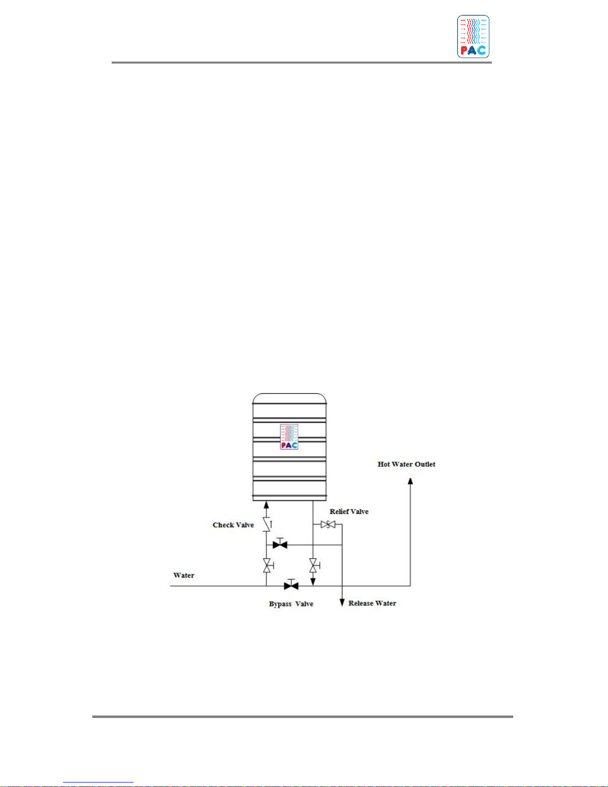
PAC Fre-Heater is equipped with 3/4" or 11/2" connections for cold water
inlet and hot water outlet, depending on the specific model
The water inlet connection is labeled “Cold” and the outlet connection is
labeled “Hot”
The pipe from the “Hot” outlet should go to the conventional water heating
system if one is used. See Figures.
A water bypass line should always be provided so the Fre-Heater(s) can be
bypassed for service without shutting down the total water heating system.
NOTE: Be sure there are no leaks at the water connections which might cause
the insulation to become wet.
IMPORTANT NOTE: To reduce the risk of excessive temperatures and pressures
in this water heater, a pressure/temperature relief valve has been installed by the
manufacturer and should not be removed. This valve should be provided with a
3
/4" drain line oriented so that any discharge from the valve will exit within 6"
above or at any distance below the structural floor and cannot contact any live
electrical part. The discharge opening must not be blocked or reduced in size
under any circumstances. Any additional protective equipment required by
local codes must also be installed. In the event that the pressure/temperature
relief valve is damaged or otherwise needs replacement, a combination
temperature and pressure relief valve, certified by a nationally recognized
testing laboratory that maintains periodic inspection of production of listed
equipment, as meeting the requirements for Relief Valves and Automatic Gas
Shut-Off Devices for Hot Water Supply Systems, ANSIZ 2 1.22-1971, should be
installed. The valve must be marked with a maximum set pressure of 150 psig
for use on all PAC Fre-Heaters.
!
14
INSTALLATION AND OPERATION MANUAL
PAC HEAT RECOVERY WATER HEATER
If a water mixing valve is installed in the system, make sure that check valves are in both
hot and cold water lines. If this precaution is not taken, hot water may be drawn into the
cold water system under certain system operating conditions.
In many multi-unit installations, it is advantageous to install a circulating pump and form
a loop plumbing circuit through the Fre-Heaters. This will usually increase the heat
recovery efficiency of the system by keeping the total system water volume at a uniform
temperature and picking up the most available heat from any refrigeration units which may
be running. Consult a plumbing supply house for a hot water circulating pump suitable for
your particular installation. All pumps used in a Fre-Heater water circulation system must
be suitable for potable water use. . Multiple Fre-Heater installations may be piped in parallel if
care is taken to assure equal flow through all of the Fre-Heaters. Parallel plumbing is usually
reserved for installations having a common refrigeration compressor on all of the FreHeaters. Refer to in the Figure.
Under certain circumstances, it may be necessary to operate a high temperature or
booster heater loop at temperatures above those attainable or desirable in the Fre-Heater. At
those times a piping scheme should be used. This allows the Fre-Heater to operate at its
optimum heat reclaim while the system temperature is at a higher level.
Figure 14 : Installing Water Piping
15

INSTALLATION AND OPERATION MANUAL
PAC HEAT RECOVERY WATER HEATER
Figure 15 : Installing PAC Fre-Heater (through one circuit into another)
Figure 16 : Installing PAC Fre-Heater in parallel series
16

INSTALLATION AND OPERATION MANUAL
PAC HEAT RECOVERY WATER HEATER
Refrigeration Connections
Mueller Fre-Heaters are shipped with a dry nitrogen holding charge that
must be removed from the Fre-Heater piping before installation of
refrigerant piping.
Good refrigeration practices must be used while installing the Fre-Heater.
These practices are of common knowledge to the experienced refrigeration
serviceman, and only a certified, experienced refrigeration serviceman should
undertake the refrigeration connection portion of a Fre-Heater installation.
Inlet and outlet stubs are copper tube for Freon applications and stainless
steel male pipe thread for ammonia applications. The sizes of refrigeration
connections for various PAC Fre-Heaters are shown in Table 1.
On runs 8 metres or less, refrigeration lines to and from the Fre-Heater
should be the same size as the compressor discharge line.
Avoid long runs whenever possible. However, if necessary to have runs of
more than 8 metres, the lines should be upsized by one tube size. Should
there be any question about refrigeration line sizing, the equipment
manufacturer’s recommendation should be followed.
In most instances, refrigeration line runs of over 16 metres should not be
used. If they are, particular care must be taken to avoid oil traps and excessive
pressure drop in the lines.
The refrigeration lines going to and from PAC Fre-Heaters could reach
temperatures of 150°C. The refrigeration lines must be insulated to prevent a
burn hazard for personal injury or combustible substances. The insulation will
also add to the efficient operation of the Fre-Heater.
If in making tubing connections, it is necessary to cut openings into the
air-conditioning or refrigeration cabinet, the following must be observed
and provided for. Particular care must be taken if the equipment is located
outdoors.
ท
Integrity and rain tightness of the cabinet must be maintained.
ท Do not cut into a control box or enclosure containing live
mechanical parts or electrical wiring. Make openings below any
enclosures containing live mechanical parts or electrical wiring.
ท Tubing must be protected against mechanical damage by the
cabinet. The use of protective bushings is recommended.
ท Tubing connections must be made by means of high-
temperature soldering or brazing.
17

INSTALLATION AND OPERATION MANUAL
PAC HEAT RECOVERY WATER HEATER
ท Tubing must be routed such that no possibility of contacting
moving parts occurs.
ท Provide protection for tubing if the likelihood of accidental
damage occurring exists.
ท Always use a gear-type tubing bender when making bends
tubes. A conduit bender will flatten the tubing and restrict
the flow of refrigerant.
ท When installing tubing through walls or along a structural
member, be sure the tubing is isolated from these members
to avoid any transmissions or vibrations that might occur.
Table 1 for the per circuit condensing unit capacity range of the various
PAC Fre-Heater units. To assure proper condensing unit operation, stay
within the capacity range specified.
A refrigeration unit exceeding the single circuit capacity of a specific PAC
Fre-Heater may be connected to two or more Fre-Heater circuits on one
or more F re -H ea te rs ha vi ng a combined circuit capacity equal to the
refrigeration unit
When making multiple Fre-Heater circuit connections to a single
refrigeration unit, the piping to the Fre-Heater circuits should be in parallel.
Series (through one circuit into another) piping of the Fre-Heater should not
be used.
A refrigerant line discharge muffler is not necessary for proper operation
or warranty coverage in a Fre-Heater installation. However, if the Fre-Heater
is to be installed in an area where any machine noise would be
objectionable, a discharge muffler should be considered as a method of
eliminating the normal compressor pulsation noise present in all
refrigeration systems.
Typical refrigeration unit piping is shown in Figures
If there is a hot gas defrost valve, an oil separator, and/or a discharge
muffler in the compressor discharge line, the Fre-Heater must be installed
downstream of it/them. See Figure for an illustration of this.
In the event of extended compressor operation with little or no water
usage, it is possible to generate water temperatures which exceed the
100°C setting of the pressure-temperature relief valve. This will result in
repeated dumping of hot water through the relief valve.
18

INSTALLATION AND OPERATION MANUAL
PAC HEAT RECOVERY WATER HEATER
To avoid the repeated release of hot water by the pressure/temperature
relief valve, should be installed. Installation and operation instructions
for the above bypass system are included with these instructions for your
reference and the port size is large enough to allow unrestricted refrigerant
flow.
For maximum refrigeration unit efficiency and Fre-Heater heat
recovery, head pressure controls must be used.
On air-cooled refrigeration units, you must install head-pressureoperated fan controls; and on water-cooled refrigeration units, you must
install a head-pressure-operated water valve, if they are not already on the
refrigeration units. On many low temperature applications, an auxiliary
cooling fan must be installed on the compressor if the condenser fan is
cycled to maintain head pressure. Consult the compressor manufacturer for
their recommendation if you are in doubt of sufficient air flow for compressor
cooling.
Refrigerant Charge
It may be necessary to add additional charge in some refrigeration
systems. Check the sight glass and, if necessary, add refrigerant to clear
the sight glass. Final charging of the system must be done after the water
in the Fre-Heater becomes warm.
Test Run
Turn on the water supply and fill the Model PAC Fre-Heater with
water. Ensure that all water and refrigeration connections are leakfree. The unit is then ready for use. Refrigerant charge should be
checked after the system has achieved normal operating conditions.
Be sure to check for proper operation of any and all controls, valves,
etc., installed with or changed during the installation of the FreHeater, both in the refrigeration and water systems.
19

INSTALLATION AND OPERATION MANUAL
PAC HEAT RECOVERY WATER HEATER
Figure 17 : Installing Refrigerant Charge with Air-Condition
Fig ure 18 : Typical Refrigeration Connections for Single
Refrigeration Unit and Single-Circuit Piping
20

INSTALLATION AND OPERATION MANUAL
PAC HEAT RECOVERY WATER HEATER
Figure 18 : Typical Dual Refrigeration Unit Piping
21

INSTALLATION AND OPERATION MANUAL
PAC HEAT RECOVERY WATER HEATER
Figure 19 : Fre-Heater Location with Hot Gas Defrost Valve, Oil
Separator, and/or Discharge Muffler in System
22

INSTALLATION AND OPERATION MANUAL
PAC HEAT RECOVERY WATER HEATER
Figure 20 : Installing Refrigerant Charge by Heat-Exchanger
23

INSTALLATION AND OPERATION MANUAL
PAC HEAT RECOVERY WATER HEATER
Maintenance
In order to achieve the maximum life from your PAC Fre-Heaters the following
should be done annually:
1. Remove and check at least one of the two anode rods. Both anode
rods should be replaced
2. Check the operation of the pressure/temperature relief valve by
manually operating it to see that it will freely flow water should it be
required to do so. If there is any doubt that it will not function
properly, replace it.
3. Check all water fittings, valves, etc. to be sure there are no water
leaks. Repair as necessary.
4. Check the operation of all controls such as the hot gas bypass valve
aquastat, electric element controls, refrigeration head pressure
controls, or any other controls necessary for the proper operation of
the Fre-Heater and the refrigeration and/or air conditioning systems it
is connected to.
24

INSTALLATION AND OPERATION MANUAL
PAC HEAT RECOVERY WATER HEATER
Efficiency
Figure 21 :
Result of Electric Power of Compressor with out PAC
25

INSTALLATION AND OPERATION MANUAL
PAC HEAT RECOVERY WATER HEATER
Figure 22 : Result of Electric Power of Air-condition and Temperature of
Refrigerant by PAC setting have water in but not flow out
Figure 23 : Result of Electric Power of Air-condition and Temperature of
Refrigerant by PAC setting and water flow out
26

INSTALLATION AND OPERATION MANUAL
PAC HEAT RECOVERY WATER HEATER
Figure 24 : Temperature of water flow out from the Mueller
27

INSTALLATION AND OPERATION MANUAL
PAC HEAT RECOVERY WATER HEATER
APPENDIX
THE COLUMN TOWER
28

INSTALLATION AND OPERATION MANUAL
PAC HEAT RECOVERY WATER HEATER
THE COLUMN TOWER
- If you would like to open an effluent from PAC, you
should turn off the water in and out, then turn on the
effluent drain from the tank.
- If the temperature in PAC are between 35-36
Celsius, then there are some water flow out from
Pressure Relief Valve. You should adapt to Pressure
Relief Valve for flow out the water that higher
temperature.
- If the temperature in PAC is more than 80 Celsius
but there are not the effluent flow out from Pressure
Relief Valve, you should unscrew for release water
in the temperature that you want.
- If the Pressure Relief Valve can not set for that
period so should change a new Pressure Relief
Valve.
29

INSTALLATION AND OPERATION MANUAL
PAC HEAT RECOVERY WATER HEATER
30
 Loading...