

Page 1
A-CU & F87-CUAD
Automatic Spray Guns
OPERATING INSTRUCTIONS & REPLACEMENT PARTS
INSTRUCTION AND PARTS LIST A-CU & F87-8/31/2011
Supersedes Instruction and Parts List A-CU & F87-4/27/2010
WARNING: Spray materials may be harmful if inhaled or
allowed to come into contact with the skin or eyes. Consult
the product label and Material Safety Data Sheet supplied
for the spray material. Follow all safety precautions.
CAUTION: Well Venti lated Are a Requi red to remov e
fumes, d u s t o r overspray. Secure a i r h o s e a n d fluid
hose wrench t i g h t fo r sa f e t y an d to pr e v e n t le a k s .
M a x i m u m A i r P r e s s u r e 1 0 0 P. S . I .
M a x i m u m F l u i d P r e s s u r e 4 5 P . S . I .
DESCRIPTION: The A-CU and F87-CUADF Automatic Spray
Guns, are medium duty and heavy duty air actuated production
spray guns, they will cover a range of materials to include heavy
type lacquers and enamels, abrasives or pigmented material.
See Page 2 for many styles of Spray Heads and Page 4 for
information on circulating fluid bodies. When using Extensions,
material must be pressure fed for proper application.
CONNECTIONS: Spray Guns have the following: Air inlet 1/4”
N.P.T (F) and Fluid inlet 3/8” N.P.T. (M).
PACKING WASHERS: Packings are available in oil treated Leather
or PTFE for natural lubricity and higher temperatures. See Page 3.
OPERATION:
1. Mount Spray Gun in desired position.
2. Blow out all hoses (airlines) before connecting to Spray Gun
to remove foreign particles.
3. Connect hose from air supply to air inlet fitting.
4. Connect fluid supply to fluid inlet.
5. Tighten all hose connections securely.
6. Adjust air pressure to desired amount at the Air Regulator.
7. Adjust Fluid volume by turning the U-3178 Fluid Adjusting
Knob to the left or right. Note: Do not use as shutoff by
turning all the way down, it may split the tip.
8. Adjust to proper fan pattern by turning the U-2065 Fan
Control Screw to left or right. For AD-2 Air Dial Assembly
adjustment, turn U-959B Adjusting Needle Valve left or right.
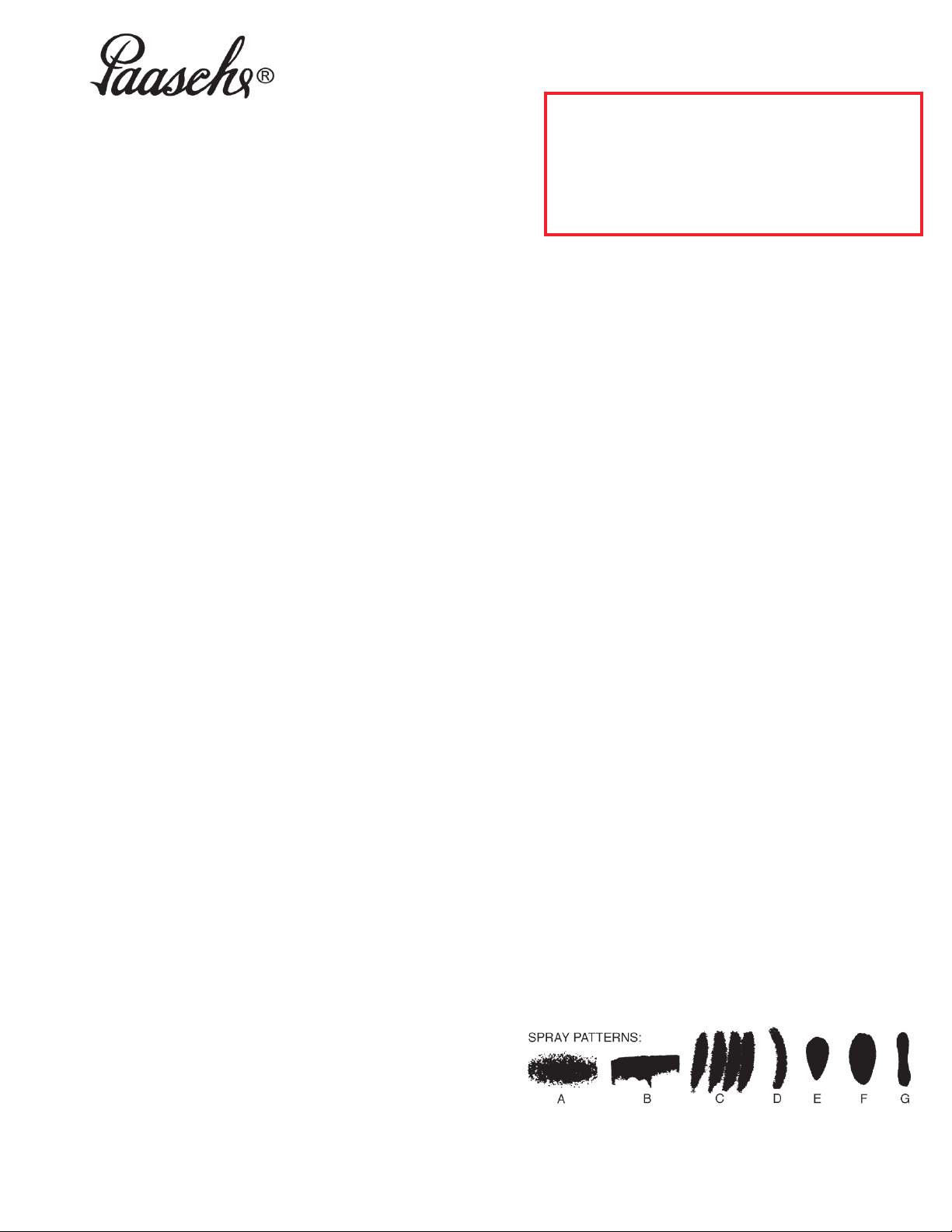
TROUBLE SHOOTING SPRAY PATTERNS:
(A) A ROUGH OR STIPPLED FINISH is caused by low or
restricted flow of air pressure or too heavy materials being
applied with gun too close to surface.
(B) A WET OR SAGGING FINISH is due to low air pressure
or restricted flow of air, material being too thin, or applied
too close to the surface.
(C) A SPUTTERING SPRAY is caused by air leaking into fluid
line or can be caused by a loose fluid tip, a broken or split
tip, lumpy material, a clogged vent hole in cover of material
cup, or air leak at fluid pipe attached to inside of tank cover,
or a clogged paint strainer. Sputtering may also be caused
by worn packing washers, or worn or scored needle.
TO CORRECT: Tighten tip securely or replace. Strain
material and clean strainer. Tighten fluid pipe in tank or
replace packings and needle in Spray Gun.
(D) AN ARCHED FAN SPRAY PATTERN is caused by dried
material accumulated in one fan port of the multiplehead,
distorting the pattern.
TO CORRECT: Dissolve material inside fan port with
suitable solvent applied with a small brush.
NOTE: Never use wire or sharp instruments to clean
Fan Ports as permanent damage to the fan ports will
result in destroying uniformity of the Fan Pattern.
TIP REPLACEMENT:
1. Turn off Air and Fluid Pressure.
2. Release Fluid Needle (A-U-4”) pressure from seat of Tip by
taking off the U-2686A Cylinder Cap Assembly.
3. Loosen U-1649 Aircap Nut and remove Multiplehead
Assembly. Leave Needle in place.
4. Unscrew U-Tip and place new U-Tip in position.
5. To reassemble reverse above procedure.
MAINTENANCE: Requirements of the A-CU & F87-CUADF
Automatic Spray Guns have been reduced to a minimum. The
leather packing washers should be lubricated with light oil or
replaced once a month. Old packing washers cause leakage of air
and Fluid. PTFE Packings are self-lubricating.
CLEANING: After each use flush clean solvent through the fluid
passages of the Spray Gun and Wipe off the outside with clean
solvent. Never leave the entire Spray Gun immersed in solvent.
Dirty Aircaps and Tips should be cleaned by soaking in solvent and
blown clean with air.
Paasche Airbrush Company
4311 North Normandy Avenue
Chicago, IL 60634-1395
Phone: 773-867-9191 • Fax: 773-867-9198
Website: paascheairbrush.com
E-Mail: info@paascheairbrush.com
(E) UNBALANCED FAN SPRAY PATTERN, heavy on one
side, may be caused by material collecting around outside
of the fluid tip and aircap, or by a loose aircap.
TO CORRECT: Remove aircap and clean fluid tip and
aircap with solvent then dry with air. Always be sure fan
aircap and aircap body are tightened securely.
(F) A HEAVY CENTER in a fan pattern is caused by
insufficient air pressure at the fan port. Rough or shady
edges are also caused by low air pressure.
TO CORRECT: Increase air line pressure.
(G) A SPLIT FAN SPRAY PATTERN, heavy on each end and
light in the center, is caused by excessive air pressure.
TO CORRECT: Reduce air pressure.
Printed in the U.S.A.
Page 2

SPRAY HEAD COMPONENTS
Spray Heads for A-CU & F87-CUAD Automatic Spray Guns are available in several different styles, some of which are available with
Stainless Steel components. The C.F.M. requirements range from 3 to 24 C.F.M. @ 40 to 50 lbs. air pressure. NOTE: When either fluid
Tip or fluid Needle is worn and requires replacement, it is recommended that both items be changed for best results. All Tips and
Needles are made using 303 Stainless Steel. Carbide Tips & Needles are available for use with abrasive materials. When using
Extensions, material must be pressure fed for proper application of material.
EXTERNAL- FAN PATTERN
• Application: Broad coverage - High Production.
• Sizes: 000-3, 00-4, 00-4-6, 06, 0-9, 2-8, 4-10, 4-15.
• Fluid Viscosity: Light to Heavy (3 to 24 C.F.M.@ 40 or 50 P.S.I.)
1. 56FA- Aircap Body (Select Size above)
2. U-2639S Sleeve & Spring
4. U-1649 Aircap Nut
5. U- Stainless Tip (Select Size 000,00,0,2,4)
6. A-U-4 Stainless Needle
INTERNAL- ROUND PATTERN
• Application: Narrow trim, inside crevice, dot, line, High Production.
• Sizes: 2-5, 4-6.
• Fluid Viscosity: Light to Medium (3 to 6 C.F.M. @ 40 P.S.I.)
1. 56RA- Aircap Body (Select Size above)
2. U-1649 Aircap Nut
3. U- Stainless Tip (Select Size 2 or 4)
4. A-U-4 Stainless Needle
CARBIDE INSERT- FAN PATTERN
• Application: Abrasive Materials
• Sizes: 0-9, 2-8 or 4-10
• Fluid Viscosity: Light to Medium (4 to 12 C.F.M. @40 or 50 P.S.I.)
1. 56CFA- Aircap Body (Select Size above)
2. U-2639S Sleeve & Spring
3. U-1649 Aircap Nut
4. UC- Carbide Insert Stainless Body Tip (Select Size 0, 2 or 4)
5. A-UC-4 Carbide Insert Stainless Needle
CARBIDE INSERT- ROUND PATTERN
• Application: Abrasive Materials
• Sizes: 2-5 & 4-6
• Fluid Viscosity: Light to Medium (3 to 6 C.F.M. @ 40 P.S.I.)
1. 56CRA- Aircap Body (Select Size above)
2. U-1649 Aircap Nut
3. UC- Carbide Insert Stainless Body Tip (Select Size 2 or 4)
4. A-UC-4 Carbide Insert Stainless Needle
StainleSS Steel
• Application: Corrosive materials and Latex.
• Sizes: 0-6, 0-9, 2-8, 4-10, 4-20-3.
• Fluid Viscosity: Light to Medium Heavy (4 to 20 C.F.M. @ 40 or 50 P.S.I.)
1. 56SFA- Stainless Aircap Body (Select Size above)
2. U-2639P Poly Sleeve
3. U-1649 Aircap Nut (plated brass)
4. U- Stainless Tip (Select Size 0, 2 or 4)
5. A-U-4 Stainless Needle
- FAN PATTERN
Page 2
Page 3

11. CU-7B Fluid Body
U-2072A Fan Control Assembly
13. AE-43 “O” Ring (1)
15. U-2065 Fan Control Screw
U-3502 Packing Set
17. U-28-12 Packing Washers (12)
18. U-29 Packing Gland (1)
19. DU-30 St. St. Spring (1)
20. U-203 Gland (1)
24. U-322 Cup Leather (1)
A-CU AND F87-CUAD
U-1914B Cylinder Assembly
6. A-U-4 Needle
20. U-203 Gland †
17. U-28-12 Packing Washers (3) †
21. U-1907B Shell Assembly
9. U-3633 Large “O” Ring
10. U-3632 Small “O” Ring
27. U-2966 Piston Spring
U-873E
22. U-2965 Needle Chuck
23. U-2964 Inner Bushing
24. U-322 Cup Leather †
25. U-2465A Outer Disc
26. U-2544 Locknut
U-2686A Cylinder Cap Assembly
28. U-2707A Cylinder Cap
29. U-941 Spring Washer
30. U-951B Fluid Dial
31. U-2675A Friction Nut
32. U-1098 St. St. Spring
33. U-2584P Washer
34. 59-57 Lock Stud
35. U-3178 Fluid Adjusting Knob ††
36. 59-56 Lock Screw
59-30 PTFE Packing Set
37. U-3353 Packing PTFE (2)
38. 59-24 Packing PTFE (4)
39. 59-25B Packing Expander (2)
19. DU-30 St. St. Spring (1)
Piston Assembly
AD-2 Air Dial Assembly
54. U-3255 Use N-1/4 & U-3321 Tube Assembly
55. U-3256 Packing Nut
56. U-3257 PTFE Packing
57. U-3258 Air Valve Body
58. U-2734A Packing Housing
59. DU-28-12 Packing Washers (1)
60. U-27 Packing Gland
61. U-1702 Valve Spring
62. U-48 Strainer Nut
63. U-941 Spring Washer
64. PA-14A Dial
65. U-2675A Friction Nut
66. U-1098 Spring St. St.
67. U-959 Adjusting Needle Valve
69. U-3548 Packing Washer
52. US- 0, 2 or 4 Self Cleaning Tip
(US-0 same as U-0)
53. A-US-0-4, 2-4, 4-4 Self Clean Needle
Use to prevent buildup in tip & pressure feed.
59-68 PTFE Piston Assembly
22. U-2965 Needle Chuck
26. U-2544 Locknut
40. 59-63 Piston
41. 59-64 Piston Rings (2)
42. 59-65 Expansion Spring
†† WARNING: Do not use U-3178 as a shut-off
by turning all the way down - it will split the tip.
† This item included in U-3502 Packing Set.
U-28-12 & DU-28-12 sold by the dozen only.
Page 3
Page 4

FLUID BODIES, EXTENSIONS, NEEDLES, AND ACCESSORIES
F87-CUAD Fluid Body Atomizing Air Dial Control
(Also in Stainless Steel)
71. U-959 Fan Screw
72. U-1098 St. St. Spring
73. U-942 Friction Nut
74. PA-14B Dial
75. U-941 Spring Washer
76. U-957 Bushing
77. DU-30 St. St. Spring (2)
78. U-27 Packing Gland (2)
79. DU-28-12 Packing Washer (1) †
80. 87-20 Fluid Body
81. U-28-12 Packing Washer (4) †
82. U-29 Packing Gland
CU- Fluid Bodies
83. CU-7B Standard
CUS-7B Standard Stainless Steel
84. CUA-7B Separate Atomizing
CUSA-7B Separate Atomizing Stainless St.
85. CUG-7B Circulating Fluid
† U-28-12 & DU-28-12 Packing Washers sold by dozen only.
PTFE Needle Packings and Piston Rings are available
Teflon Needle Packings & Piston add XX after A or F87
Page 4
 Loading...