

paasche A-C2F-4-10C, A-C2R-2-5C, A-C2F-0-9C, A-C2F-2-8C, A-C2R-4-6C Operating Instructions And Replacement Parts
Page 1

A-C2F-4-10C/-2-8C/-0-9C
A-C2R-4-6C/-2-5C
Abrasive Automatic Spray Guns
OPERATING INSTRUCTIONS & REPLACEMENT PARTS
INSTRUCTION AND PARTS LIST A-C2F-4-10C 11/20/2017
WARNING: Spray materials may be harmful if inhaled or
allowed to come into contact with the skin or eyes. Consult
the product label and Material Safety Data Sheet supplied
for the spray material. Follow all safety precautions.
CAUTION: Well Ventilated Area Required to remove
fumes, dust or overspray. Secure airhose and fluid
hose wrench tight for safety and to prevent leaks.
M a x i m u m A i r P r e s s u r e 1 0 0 P. S . I .
M a x i m u m F l u i d P r e s s u r e 4 5 P. S . I .
DESCRIPTION:The Automatic Spray Gun is an actuated
production spray gun, it includes Carbide Tip and Needle for
abrasives or pigmented material.See Page 2 for spray head
options.
CONNECTIONS: Spray Gun has the following: Air inlet 1/4”
N.P.T (F) and Fluid inlet 3/8” N.P.T. (M).
PACKING WASHERS: Packings are available in oil treated Leather
or PTFE for natural lubricity and higher temperatures. See Page 2.
OPERATION:
1. Mount Spray Gun in desired position.
2. Blow out all hoses (airlines) before connecting to Spray Gun
to remove foreign particles.
3. Connect hose from air supply to air inlet fitting.
4. Connect fluid supply to fluid inlet.
5. Tighten all hose connections securely.
6. Adjust air pressure to desired amount at the Air Regulator.
7. Adjust Fluid volume by turning the Fluid Adjusting Knob to
the left or right. Note: Do not use as shutoff by turning
all the way down, it may split the tip.
8. Adjust to proper fan pattern by turning the Fan Control
Screw to left or right.
TIP REPLACEMENT:
1. Turn off Air and Fluid Pressure.
2. Release Fluid Needle pressure from seat of Tip by taking off
the Cylinder Cap Assembly.
3. Loosen Aircap Nut and remove Multiplehead Assembly.
Leave Needle in place.
4. Unscrew Tip and place new Tip in position.
5. To reassemble reverse above procedure.
MAINTENANCE: Requirements of the Automatic Spray Gun have
been reduced to a minimum. The leather packing washers should
be lubricated with light oil or replaced once a month. Old packing
washers cause leakage of air and Fluid. PTFE Packings are selflubricating.
CLEANING: After each use flush clean solvent through the fluid
passages of the Spray Gun and Wipe off the outside with clean
solvent. Never leave the entire Spray Gun immersed in solvent.
Dirty Aircaps and Tips should be cleaned by soaking in solvent and
blown clean with air.
TROUBLE SHOOTING SPRAY PATTERNS:
(A) A ROUGH OR STIPPLED FINISH is caused by low or
restricted flow of air pressure or too heavy materials being
applied with gun too close to surface.
(B) A WET OR SAGGING FINISH is due to low air pressure
or restricted flow of air, material being too thin, or applied
too close to the surface.
(C) A SPUTTERING SPRAY is caused by air leaking into fluid
line or can be caused by a loose fluid tip, a broken or split
tip, lumpy material, a clogged vent hole in cover of material
cup, or air leak at fluid pipe attached to inside of tank cover,
or a clogged paint strainer. Sputtering may also be caused
by worn packing washers, or worn or scored needle.
TO CORRECT: Tighten tip securely or replace. Strain
material and clean strainer. Tighten fluid pipe in tank or
replace packings and needle in Spray Gun.
(D) AN ARCHED FAN SPRAY PATTERN is caused by dried
material accumulated in one fan port of the multiplehead,
distorting the pattern.
TO CORRECT: Dissolve material inside fan port with
suitable solvent applied with a small brush.
NOTE: Never use wire or sharp instruments to clean
Fan Ports as permanent damage to the fan ports will
result in destroying uniformity of the Fan Pattern.
(E) UNBALANCED FAN SPRAY PATTERN, heavy on one
side, may be caused by material collecting around outside
of the fluid tip and aircap, or by a loose aircap.
TO CORRECT: Remove aircap and clean fluid tip and
aircap with solvent then dry with air. Always be sure fan
aircap and aircap body are tightened securely.
(F) A HEAVY CENTER in a fan pattern is caused by
insufficient air pressure at the fan port. Rough or shady
edges are also caused by low air pressure.
TO CORRECT: Increase air line pressure.
(G) A SPLIT FAN SPRAY PATTERN, heavy on each end and
light in the center, is caused by excessive air pressure.
TO CORRECT: Reduce air pressure.
Paasche Airbrush Company
9511 58th Place
Kenosha, WI 53144
Phone: (800) 621-1907
Website: paascheairbrush.com
E-Mail: info@paascheairbrush.com
Printed in the U.S.A.
Page 2
11.
C-31
U-3651 Fan Control Assembly
13. 3A-4 “O” Ring (1) (6 pack)
15. U-3651 (Fan Control Screw)
U-3502 Packing Set
17. U-28-12 Packing Washers (12)
18. U-29 Packing Gland (1)
19. DU-30 St. St. Spring (1)
20. U-203 Gland (1)
24. U-322 Cup Leather (1)
U-1914B Cylinder Assembly
6. A-UC-4L Needle W/Carbide Tip
20. U-203 Gland †
17. U-28-12 Packing Washers (3) †
21. U-1907B Shell Assembly
9. U-3633 PTFE Large “O” Ring
10. U-3632 PTFE Small “O” Ring
27. U-2966 Piston Spring
U-873E Piston Assembly
22. U-2965 Needle Chuck
23. U-2964 Inner Bushing
24. U-322 Cup Leather †
25. U-2465A Outer Disc
26. U-2544 Locknut
U-2686A Cylinder Cap Assembly
28. U-2707A Cylinder Cap
29. U-941 Spring Washer
30. U-951B Fluid Dial
31. U-2675A Friction Nut
32. U-1098 St. St. Spring
33. U-2584P Washer
34. 59-57 Lock Stud
35. U-3178 Fluid Adjusting Knob ††
36. 59-56 Lock Screw
Fluid Body
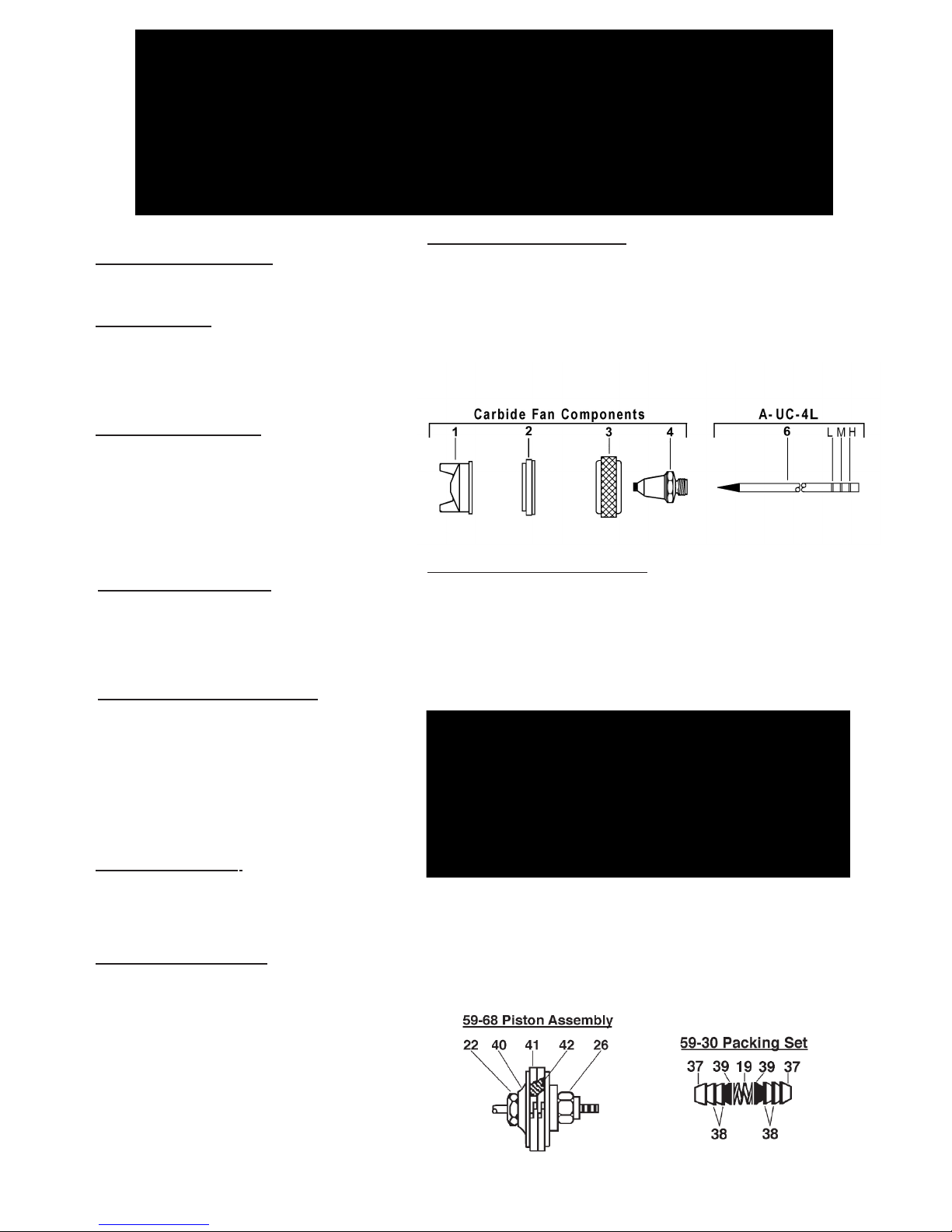
CARBIDE INSERT- FAN PATTERN
• Application: Abrasive Materials
• Sizes: 0-9(.55), 2-8(.73) or 4-10(.93)
• Fluid Viscosity: Light to Medium (4 to 12 C.F.M. @40 or 50 P.S.I.)
1. 56CFA- Aircap Body (Select Size above)
2.
U-3663 Sleeve PTFE
3. U-1649 Aircap Nut
4. UC- Carbide Insert Stainless Body Tip (Select Size 0, 2 or 4)
6. A-UC- 4L Carbide Insert Stainless Needle
CARBIDE INSERT- ROUND PATTERN
• Application: Abrasive Materials
• Sizes: 2-5(.73) & 4-6(.93)
• Fluid Viscosity: Light to Medium (3 to 6 C.F.M. @ 40 P.S.I.)
1. 56CRA- Aircap Body (Select Size above)
2. U-1649 Aircap Nut
3. UC- Carbide Insert Stainless Body Tip (Select Size 2 or 4)
6. A-UC- 4L Carbide Insert Stainless Needle
59-30 PTFE Packing Set
37. U-3353 Packing PTFE (2)
38. 59-24 Packing PTFE (4)
39. 59-25B Packing Expander (2)
19. DU-30 St. St. Spring (1)
59-68 PTFE Piston Assembly
22. U-2965 Needle Chuck
26. U-2544 Locknut
40. 59-63 Piston
41. 59-64 Piston Rings (2)
42. 59-65 Expansion Spring
†† WARNING: Do not use U-3178 as a shut-off
by turning all the way down - it will split the tip.
† This item included in U-3502 Packing Set.
U-28-12 & DU-28-12 sold by the dozen only.
OPTIONAL : items below sold seperately
PTFE
PTFE
Page 2
Page 3

OPTIONAL ACCESSORIES
HA-1/4-10
FLUID HOSE
HT-1/4-10
UM-20
MOUNTING ASSEMBLY
AIR HOSE
GT-25 1S-13
PAINT PRESSURE TANK
page3
AIRMOTOR AGITATOR
Page 4

 Loading...