

Page 1
A-BU
AUTOMATIC SPRAY GUNS
OPERATING INSTRUCTIONS AND REPLACEMENT PARTS
INSTRUCTIONS AND PARTS LIST A-BU-8/31/2011
Supersedes Instructions & Parts List A-BU-4/27/2010
WARNING: Spray materials may be harmful if inhaled or
allowed to come into contact with the skin or eyes. Consult
the product label and Material Safety Data Sheet supplied
for the spray material. Follow all safety precautions.
CAUTION: Well Venti late d Area Re quir e d t o r e move
fumes, dust or overspray. Secure airhose and fluid
hose wrench t i g h t f o r safety and t o pr e v e n t leaks .
M a x i m u m A i r P r e s s u r e 1 0 0 P . S . I .
M a x i m u m F l u i d P r e s s u r e 4 5 P . S . I .
DESCRIPTION:
The A-BU- Automatic Spray Gun, a medium duty air actuated
production spray gun, will cover a range of materials to include
light lacquers, abrasives or latex and corrosives.
AIR AND FLUID CONNECTIONS:
Air Inlet 1/4" N.P.T. (Female) and Fluid Inlet 3/8" N.P.T. (Male). ABU- Automatic Spray Gun dimensions are 5-1/8"L x 2-1/4"D.
Packing Washers are treated leather and soaked in oil. For PTFE
Packings see page 3.
OPERATION:
1. Mount Gun in desired position.
2. Blow out all hoses before connecting to spray gun to
remove foreign particles.
3. Connect hose from air supply to air inlet fitting.
4. Connect fluid supply to fluid inlet.
5. Tighten all hose connections securely.
6. Adjust air pressure to desired amount at the air regulator.
7. Adjust fluid volume by turning the U-3178 Fluid Adjusting
Knob to the left (Increase) or right (Decrease).
NOTE: DO NOT USE AS A SHUT-OFF BY TURNING ALL
THE WAY DOWN, IT MAY SPLIT THE TIP.
TIP REPLACEMENT:
1. Turn off air pressure and fluid pressure.
2. Release needle pressure from the seat of fluid tip by
taking off the U-2686A Cylinder Cap Assembly. This will
relieve the spring pressure.
3. Loosen BU-12 Aircap Nut and remove Spray Head
assembly. Leave A-U-4 Needle in place.
4. Unscrew U- Tip. Place new tip in position.
5. When replacement is complete reassemble by reversing
the above procedure.
TROUBLE SHOOTING SPRAY PATTERNS:
A. A ROUGH OR STIPPLED FINISH is caused by low or
restricted flow of air pressure or too heavy materials being
applied with gun too close to surface.
B. A WET OR SAGGING FINISH is due to low air pressure or
restricted flow of air, material being too thin, or applied too
close to the surface.
C. A SPUTTERING SPRAY can be caused by air leaking into fluid
line, a loose fluid tip, a broken or split tip, lumpy material, a
clogged vent hole in cover of material cup, an air leak at fluid pipe
attached to inside of A.S.M.E. Tank cover, or a clogged paint
strainer. Sputtering may also be caused by worn packing
washers, or worn or scored needle.
TO CORRECT: Tighten tip securely or replace. Strain
material and clean strainer. Tighten fluid pipe in tank or
replace packings and needle in Spray Gun.
D. AN ARCHED FAN SPRAY PATTERN is caused by dried
material accumulated in one fan port of the fan aircap,
distorting the pattern.
TO CORRECT: Dissolve material inside fan port with
suitable solvent applied with a small brush.
NOTE: Never use wire or sharp instruments to clean
Fan Ports as permanent damage to the fan ports will
result in destroying uniformity of the fan pattern.
E. UNBALANCED FAN SPRAY PATTERN, heavy on one side,
may be caused by material collecting around outside of the
fluid tip and aircap, or by a loose aircap.
TO CORRECT: Remove aircap and clean fluid tip and
aircap with solvent then dry with air. Always be sure fan
aircap and aircap body are tightened securely.
MAINTENANCE:
Requirements of the A-BU- Automatic Spray Gun have been
reduced to a minimum. The leather packing washers should be
lubricated once a month with a light oil. Old packing washers
cause leakage of air or fluid and replacement should be made on
a regular schedule. PTFE Packings are available and are self
lubricating.
CLEANING:
Flush appropriate solvent through fluid passages of the Spray
Gun and wipe off the outside with a clean cloth. Never leave the
entire Spray Gun immersed as this will ruin leather packings.
Dirty aircaps and tips should be cleaned by soaking, then drying.
Paasche Airbrush Company
4311 North Normandy Avenue
Chicago, IL 60634-1395
Phone: 773-867-9191 • Fax: 773-867-9198
Website: paascheairbrush.com
E-Mail: info@paascheairbrush.com
F. A HEAVY CENTER in a fan pattern is caused by insufficient air
pressure at the fan port. Rough or shady edges are also
caused by low air pressure.
TO CORRECT: Increase air line pressure.
G. A SPLIT FAN SPRAY PATTERN, heavy on each end and light
in the center, is caused by excessive air pressure.
TO CORRECT: Reduce air pressure.
Printed in the U.S.A.
Page 2
SPRAY HEAD COMPONENTS Pag e 2
Spray Heads for A-BU- Automatic Spray Guns are available in several different Styles, some of which are available with Stainless
Steel components. The C.F.M. requirements range from 2 to 14 C.F.M. @ 30 to 40 lbs. air pressure. NOTE: When either fluid
Tip or fluid Needle is worn and requires replacement, it is recommended that both items be changed for best results. All Tips
and Needles are made using 303 Stainless Steel. Carbide Tips and Needles are available for use with abrasive materials.
•
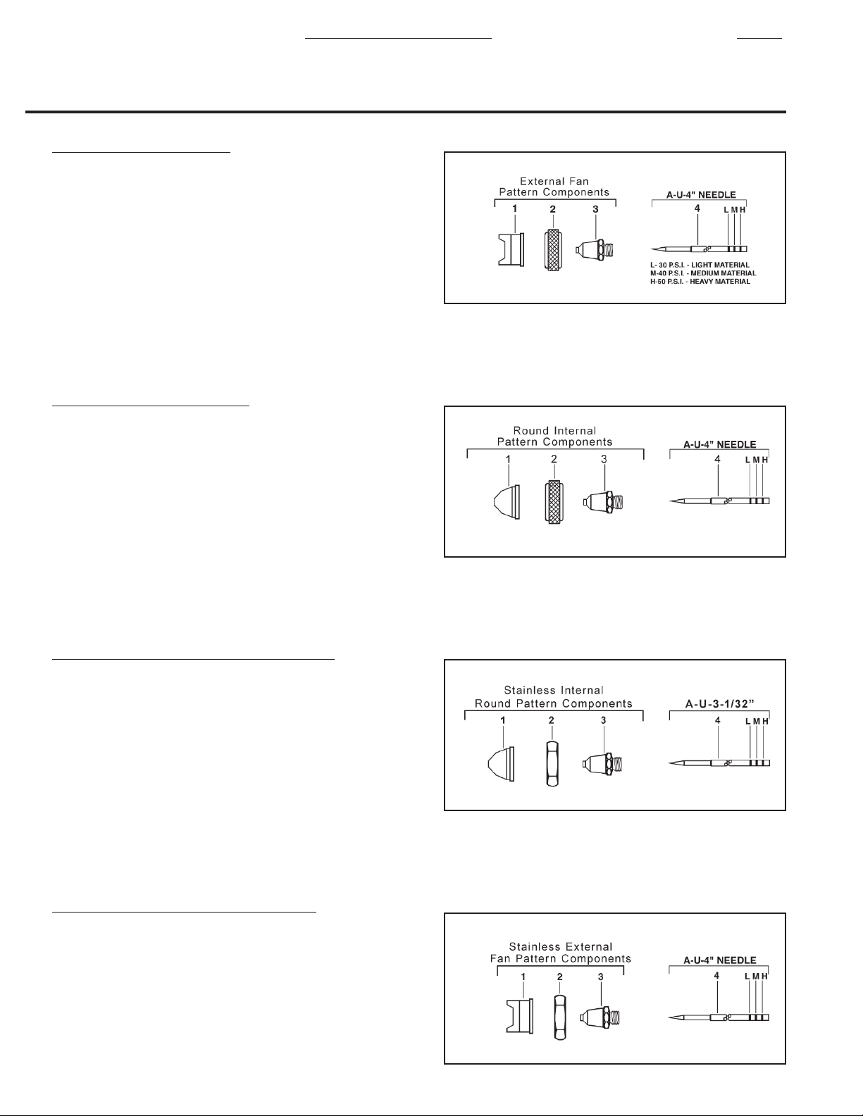
EXTERNAL- FAN PATTERN
•
Sizes: 2 or 4
•
Application: Application in tight areas - fast color change.
•
Fluid Viscosity: Light to Medium (2 to 6 C.F.M. @ 30 P.S.I.)
1. BNFA- Fan Aircap (Select Size)
2. BU-12 Aircap Nut
3. U- Stainless Tip (Select Size)
4. A-U-4 Stainless Needle
•
INTERNAL- ROUND PATTERN
•
Sizes: 2 or 4
•
Application: Fine lines, detailing stenciling and touch-up.
Latex, silver nitrate, acidic materials.
•
Fluid Viscosity: Light to medium (2 to 3.5 C.F.M. @ 40 P.S.I.)
1. BR-15- Aircap Body (Select Size)
2. BU-12 Aircap Nut
3. U- Stainless Tip (Select Size)
4. A-U-4 Stainless Needle
•
STAINLESS- INTERNAL- ROUND PATTERN
•
Sizes: 2 or 4
•
Application: Fine lines, detailing stenciling and touch-up.
Latex, silver nitrate, acidic materials.
•
Fluid Viscosity: Light to medium (2 to 3.5 C.F.M. @ 40 P.S.I.)
1. BSR-15- Stainless Aircap Body
2. BUS-12 Stainless Aircap Nut
3. U- Stainless Tip (Select Size)
4. A-U-3-1/32 Stainless Needle
•
STAINLESS- EXTERNAL- FAN PATTERN
•
Sizes: 0 only
•
Application: Corrosive materials.
•
Fluid Viscosity: Light to Medium (3 to 5 C.F.M. @ 40 P.S.I.)
1. BSF-15- Stainless St. Fan Aircap (Select Size)
2. BUS-12 Stainless St. Aircap Nut
3. U- Stainless Tip (Select Size)
4. A-U-4 Stainless Needle
Page 3

A-BU Auto. Spray Gun Components
BU- Fluid Bodies
1. BU-7B Standard
BUS-7B Standard Stainless Steel
1d. BU-7DA Atomizing Air Dial Control
U-3502 Packing Set
2. U-28-12 Packing Washers (Dozen)
3. U-29 Packing Gland (1)
4. DU-30 Spring (1)
5. U-203 Gland (1)
14. U-322 Cup Leather (1)
Page 3
U-1914B Cylinder Assembly
6. A-U-4 Needle
5. U-203 Gland
2. U-28-12 Packing Washers (3)
10. U-1907B Shell
8. U-3633 Large “O” Ring
9. U-3632 Small “O” Ring
11. U-2966 Piston Spring
U-873E Piston Assembly
12. U-2965 Needle Chuck
13. U-2964 Inner Bushing
14. U-322 Cup Leather
15. U-2465A Outer Disc
16. U-2544 Locknut
U-2686A Cylinder Cap Assembly
17. U-2707A Cylinder Cap
18. U-941 Spring Washer
19. U-951B Fluid Dial
20. U-2675A Friction Nut
21. U-1098 Spring
22. U-2584P Washer
23. 59-57 Lock Stud
24. U-3178 Fluid Adjusting Knob †
25. 59-56 Lock Screw
† NOTE: Do not use as a shut-off by turning
all the way down. This may damage the tip.
59-30 PTFE Packing Assembly
26. U-3353 Packing PTFE (2)
27. 59-24 Packing PTFE (4)
28. 59-25B Expander (2)
29. DU-30 Spring (1)
A. Independent Atomizing Needle
Valve Body Assembly
34. U-166A Needle Valve Assem.
35. U-167 Spring Cap
36. DU-30 Spring
37. U-203 Gland (2)
38. U-28-12 Packing Washers (2)
1d. BU-7DA Fluid Body
39. U-551 Cap Nut
B. Atomizing Air Dial Control
40. U-959 Air Adjusting Needle
41. U-1098 Spring
42. U-942 Friction Nut
43. PA-14 Dial
44. U-941 Spring Washer
45. U-957 Bushing
46. DU-30 Spring
47. U-27 Packing Gland (1)
48. DU-28-12 Packing Washers (2)
1d. BU-7DA Fluid Body
49. U-551 Cap Nut
•
U-28-12 and DU-28-12 Packing
Washers sold by the dozen (12) only.
59-68 PTFE Piston Assembly
30. U-2965 Needle Chuck
31. 59-63 Aluminum Piston
32. 59-64 PTFE Piston Ring(2)
33. 59-65 Expansion Spring
34. U-2544 Locknut
PTFE Needle Packings and Pistons are available in any model at additional
charge.
•
Add letter: “X” after A for Teflon Needle Packings Only.
Example: A-BUF-2 becomes AX-BUF-2.
•
Add letters: “XX” after A for Teflon Needle Packings and Piston.
Page 4

ACCESSORIES
Page 4
GT-25
Automatic Hook-Up
INSTRUCTIONS:
Blow out all the hoses to remove foreign particles. Make Air and Fluid connections as shown. Tighten fittings securely.
Strain material before placing in tank.
1. Air Compressor must have sufficient capacity for application.
2. Air Regulator; adjust pressure required to operate Striping Gun, Approximately 45 P.S.I.
3. Explosion-proof Solenoid Valve with air dump feature, mount as close to Gun as possible for fast on-off action.
4. Pressure Tank GT-25; adjust Regulator on Tank Unit to minimum pressure required to deliver fluid to Striping Gun #5.
 Loading...