

Page 1
INSTRUCTIONS AND PARTS LIST A-AUAX-8/31/2011
Supersedes Instruction & Parts List A-AUAX-4/27/2010
A - A U N F - E 3
A - A U A X - 3
A - A U A X - 3 D
A - A U - L / H e a d
Automatic Spray Guns
OPERATING INSTRUCTIONS AND REPLACEMENT PARTS
DESCRIPTION: The A-AU Automatic Spray Gun is a light duty air
actuated production spray gun. It will cover a range of materials to
include light lacquers, latex, acid or corrosives.
CONNECTIONS to the gun are: Air Inlet 1/4" N.P.T. (F) and Fluid
Inlet 1/4” N.P. T. (M). A-AU Automatic Spray Gun dimensions are:
5-1/8" (L) x 2 1/4” (D)
PACKING WASHERS are leather and treated in oil. For Teflon*
Packings see parts list, Page 3.
OPERATION:
1. Mount Gun in desired position
2. Before installing, blow out air hoses with compressed air to
remove foreign particles.
3. Connect hose from air supply to air inlet fitting.
4. Connect fluid hose to fluid inlet supply.
5. Tighten all hose connections securely.
6. Adjust air pressure to 45-55 P.S.I. at your Air Regulator.
7. Adjust fluid volume by turning the U-3178 Fluid Adjusting
Knob to the left or right.
NOTE: DO NOT USE AS A SHUT-OFF BY TURNING ALL
THE WAY DOWN - IT MAY SPLIT THE TIP. Use
minimum fluid pressure, 5 P.S.I. for light
materials and up to 10 P.S.I. for heavier materials.
WARNING: Spray materials may be harmful if inhaled or
allowed to come into contact with the skin or eyes. Consult
the product label and Material Safety Data Sheet supplied
for the spray material. Follow all safety precautions.
CAUTION: Well Ven til ate d A rea Re qui red to re mov e
fum e s, d ust or over s pray. Secu r e a i rhos e a n d f l uid
hos e wre n c h ti g ht f o r saf e ty a n d to p reve n t lea k s.
M a x i m u m A i r P r e s s u r e 1 0 0 P . S . I .
M a x i m u m F l u i d P r e s s u r e 4 5 P . S . I .
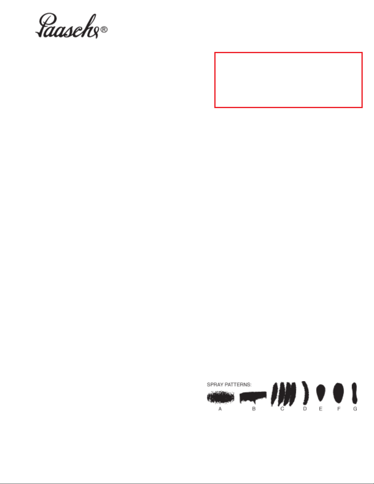
TROUBLE SHOOTING SPRAY PATTERNS:
(A) A ROUGH OR STIPPLE FINISH is due to low or restricted flow of air
pressure or too heavy materials being applied with spray gun too close
to surface.
(B) A WET OR SAGGING FINISH is due to low air pressure or restricted
flow of air, material being too thin, applied too close to the surface.
(C) A SPUTTERING SPRAY is caused by air leaking into fluid line or can
be caused by a loose fluid tip, a broken or split tip, lumpy material, a
clogged vent hole in cover of material cup, or air leak at fluid pipe
attached to inside of tank cover, or a clogged paint strainer. TO
CORRECT: Tighten tip securely or replace. Strain materials and clean
strainer. Sputtering might also be caused by worn packing washers, or
worn or scored needle
(D) AN ARCHED FAN SPRAY PATTERN is caused by dried material
accumulated in one fan port of the multiplehead distorting the pattern.
TO CORRECT: Dissolve material inside fan port with suitable solvent
applied with a small brush.
NOTE: Never Use Wire or Sharp Instruments to Clean Fan
Ports as Permanent Damage to the Air Ports Will Result In
Destroying Uniformity of the Fan Pattern.
TIP REMOVAL:
1. Turn off Air and Fluid Pressure.
2. Release Needle pressure from the seat of Tip, by backing off
the U-3178 Fluid Adjusting Knob approximately 5 turns, then
removing U-2686A Cylinder Cap Assembly.
3. Loosen AU-12 Aircap Nut and remove Multiplehead
Assembly. Leave Needle in place.
4. Unscrew AU-Tip. Place New AU-Tip in position.
5. To replace, reverse above procedure.
MAINTENANCE: Requirements of the A-AU- Automatic Spray
Gun have been reduced to a minimum. The leather packing
washers should be lubricated once a month with a light oil. Old
Packing Washers cause leakage of Air or Fluid and replacement
should be made. Teflon Packings are self-lubricating.
CLEANING: Flush clean solvent through the Fluid passages of the
Spray Gun and Wipe off the outside with clean solvent. Never leave
the entire Spray Gun immersed in solvent. Dirty Aircaps and Tips
should be cleaned by soaking in solvent and blown clean with air.
Paasche Airbrush Company
4311 North Normandy Avenue
Chicago, IL 60634-1395
Phone: 773-867-9191 • Fax: 773-867-9198
Website: paascheairbrush.com
E-Mail: info@paascheairbrush.com
(E) UNBALANCED FAN SPRAY PATTERN heavy on one side, may be
caused by material collecting around outside of the fluid tip and aircap,
or by a loose aircap. TO CORRECT: Remove aircap and clean fluid tip
and aircap with solvent, dry with air pressure. Always be sure fan
aircap is tightened securely.
(F) A HEAVY CENTER in a fan pattern is caused by insufficient air
pressure at the fan port. Rough or shady edges are also caused by low
air pressure. TO CORRECT: Increase air line pressure.
(G) A SPLIT FAN SPRAY PATTERN heavy on each end and light in the
center, is caused by excessive air pressure. TO CORRECT: Reduce
air pressure.
Printed in the U.S.A.
Page 2
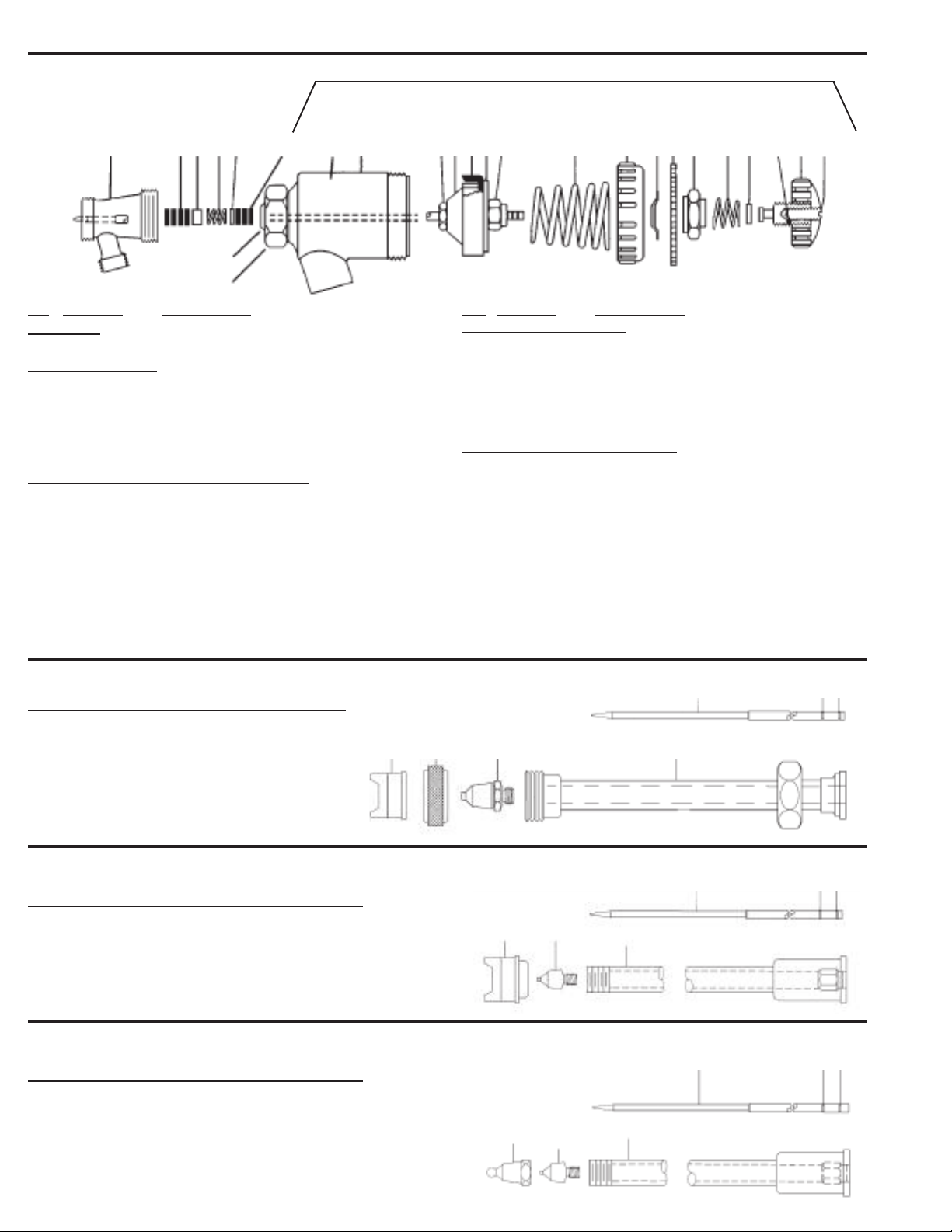
A-AU Less Head and Less Needle
AU-1914B CYLINDER ASSEMBLY
AU-7B U-3502 U-873E U-2686A
Fluid Body Packing Set Piston Assembly Cylinder Cap Assembly
15 16 17 18 19 20 19 21 22 23 24 25 26 27 28 29 30 31 32 33 34 35 36
Includes Item 24
13
14
No Part No. Description
Fluid Body
15. AU-7B Fluid Body/L Needle
U-3502 Packing Set
16. U-28-12 Packing Washers (12)
17. U-29 Packing Gland (1)
18. DU-30 St. St. Spring (1)
19. U-203 Gland (1)
24. U-322 Cup Leather (1)
AU-1914B Cylinder Assembly Less Needle
19. U-203 Gland
20. U-28-12 Packing Washers (3) (Sold by Dozen)
21. U-1907B Shell Assembly
13. U-3632 Small “O” Ring
14. U-3633 Large “O” Ring
27. U-2966 Piston Spring
(Note: Includes U-873E & U-2686A)
27. U-2687 Light Spring Action (Special Only)
A-AUNF-E3
1. A-AU Less Head and Less Needle
2. ANFA-3 Aircap
3. AU-12 Plated Aircap Nut
4. AU-3 Tip
5. A-AU-3 Needle
6. AE-3 Extension
No. Part No. Description
U-873E Piston Assembly
22. U-2965 Needle Chuck
23. U-2964 Inner Bushing
24. U-322 Cup Leather
25. U-2465A Outer Disc
26. U-2544 Locknut
U-2686A Cylinder Cap Assembly
28. U-2707A Cylinder Cap
29. U-941 Spring Washer
30. U-951B Fluid Dial
31. U-2675 Friction Dial
32. U-1098 Spring
33. U-2584 Washer
34. 59-57 Lock Stud
35. U-3178 St. St. Fluid Adjusting Knob
36. 59-56 Lock Screw
NOTE: Do not use as a shut-off by turning all the way down,
*
23 4 6
it will split the tip!
5 LP HP
*
A-AUAX-3
1. A-AU Less Head and Less Needle
6. AXNFA-3 Aircap
7. AXNT-1 Tip
8. AX-3 Extension
5. A-AU-3 Needle
A-AUAX-3D
1. A-AU Less Head and Less Needle
9. AXIF-D Aircap
10. AX-1 Tip
8. AX-3 Extension
5. A-AU-3 Needle
5 LP HP
67 8
5 LP HP
9 10 8
 Loading...