

Page 1
A-AU
Automatic Spray Gun
OPERATING INSTRUCTIONS AND REPLACEMENT PARTS
INSTRUCTIONS & PARTS LIST A-AU 1/25/2018
WARNING: Spray materials may be harmful if inhaled or
allowed to come into contact with the skin or eyes. Consult
the product label and Material Safety Data Sheet supplied
for the spray material. Follow all safety precautions.
CAUTION: Well Ventilated Area Required to remove
fumes, dust or overspray. Secure airhose and fluid
hose wrench tight for safety and to prevent leaks.
Maximum Air Pressure 100 P.S.I.
Maximum Fluid Pressure 45 P.S.I.
DESCRIPTION:
The A-AU Automatic Spray Gun, is a light duty air actuated
production spray gun. It will cover a range of materials to include
light lacquers, latex, acid or corrosives. When using Extensions,
material must be pressure fed for proper application.
CONNECTIONS:
Connections to the gun are: Air Inlet 1/4” N.P.T. (F) and Fluid
Inlet 1/4” N.P.T. (M). A-AU Automatic Spray Gun dimensions
are: 5-1/8” (L) x 2-1/4” (D). Packings and piston are PTFE.
Spray Heads for the A-AU Automatic Spray Guns are available
in several different styles, some of which are available with
Stainless Steel components. The C.F.M. requirements
range from .25 to 3 C.F.M. @ 30 lbs. air pressure. NOTE:
When either fluid Tip or fluid Needle is worn and requires
replacement, it is recommended that both items be changed
for best results.
All Tips and Needles are made using 303 Stainless Steel.
OPERATION:
1. Mount Gun in desired position
2. Before installing, blow out air hoses with compressed air to
remove foreign particles.
3. Connect hose from air supply to air inlet tting.
4. Connect uid hose to uid inlet supply.
5. Tighten all hose connections securely.
6. Adjust air pressure to 45-55 P.S.I. at the Air Regulator.
7. Adjust uid volume by turning the U-3178 Fluid Adjusting
Knob to the left or right.
NOTE: DO NOT USE U-3178 AS A SHUT-OFF BY TURNING
ALL THE WAY DOWN - IT MAY SPLIT THE TIP.
TIP REMOVAL:
1. Turn off Air and Fluid Pressure.
2. Release Needle pressure from the seat of Tip, by backing
off the U-3178 Fluid Adjusting Knob approximately 5 turns,
then removing U-2686A Cylinder Cap Assembly.
3. Loosen AU-12 Aircap Nut and remove Spray Head
Assembly. Leave Needle In Place.
4. Unscrew AU-Tip. Place New AU-Tip in position.
5. To replace, reverse above procedure.
MAINTENANCE:
Requirements of the A-AU Automatic Spray Gun have been
reduced to a minimum. The leather packing washers should be
lubricated once a month with a light oil. Old Packing Washers
cause leakage of Air or Fluid and replacement should be made.
PTFE Packings are self-lubricating. Flush clean solvent through
the Fluid passages of the Spray Gun and Wipe off the outside
with clean solvent. Never leave the entire Spray Gun immersed
in solvent. Dirty Aircaps and Tips should be cleaned by soaking
in solvent and blown clean with air.
CLEANING:
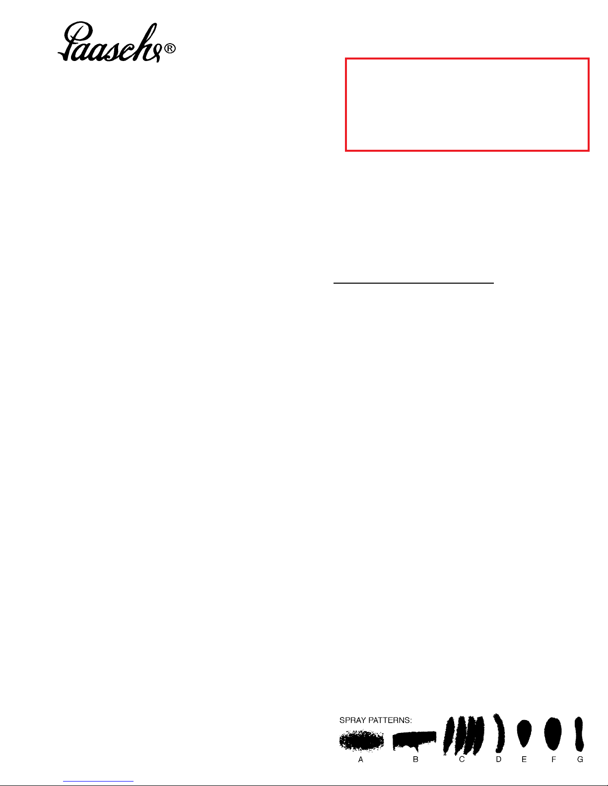
TROUBLE SHOOTING SPRAY PATTERNS:
(A) A ROUGH OR STIPPLE FINISH is due to low or restricted ow of air
pressure or too heavy materials being applied with spray gun too close
to surface.
(B) A WET OR SAGGING FINISH is due to low air pressure or restricted
ow of air, material being too thin, applied too close to the surface.
(C) A SPUTTERING SPRAY is caused by air leaking into uid line or can
be caused by a loose uid tip, a broken or split tip, lumpy material,
a clogged vent hole in cover of material cup, air leak at uid pipe
attached to inside of tank cover, or a clogged paint strainer.
TO CORRECT: Tighten tip securely or replace. Strain materials
and clean strainer. Sputtering might also be caused by worn packing
washers, or worn or scored needle.
(D) AN ARCHED FAN SPRAY PATTERN is caused by dried material
accumulated in one fan port of the fan aircap distorting the pattern.
TO CORRECT: Dissolve material inside fan port with suitable solvent
applied with a small brush.
NOTE: Never use wire or sharp instruments to clean fan ports
as permanent damage to the air ports will result in destroying
uniformity of the fan pattern.
(E) UNBALANCED FAN SPRAY PATTERN, heavy on one side, may
be caused by material collecting around outside of the uid tip and
aircap, or by a loose aircap.
TO CORRECT: Remove aircap and clean uid tip and aircap with
solvent, dry with air pressure. Always be sure fan aircap and aircap
body is tightened securely.
(F) A HEAVY CENTER in a fan pattern is caused by insufcient air
pressure at the fan port. Rough or shady edges are also caused by
low air pressure.
Paasche Airbrush Company
4311 North Normandy Avenue
Chicago, IL 60634-1395
Phone: 773-867-9191 • Fax: 773-867-9198
Website: paascheairbrush.com
E-Mail: info@paascheairbrush.com
TO CORRECT: Increase air line pressure.
(G) A SPLIT FAN SPRAY PATTERN heavy on each end and light in the
center, is caused by excessive air pressure.
TO CORRECT: Reduce air pressure.
Page 2
Paasche A-AU Automatic Spray Gun
12
1 2
5
1 6
4
3
13 11
No. Part No. Description
1. A-AU-3-11/16 Needle
2. AU-7B Fluid Body
3. U-3680 PTFE Packing Set
4. U-3632 Small “O” Ring
5. U-36 Large “O” Ring
6. U-1907B Shell Assembly
7. U3656 PTFE Piston Assembly
8. U-2966 Piston Spring
9. U-2686A Cylinder Cap Assembly
10. AU-
11. AU-12 Aircap Nut
12. ANFA- Fan Aircap (Select Size 000/0, 1, 2 or 3)
12B . ANFAS- Stainless Fan Aircap (Select Size 000/0 or 1)
13
. AR-15 Round Aircap (Select Size000/0, 1, 2 or 3)
13B. ASR-15
10
Stainless Tip (Select Size 000, 0, 1, 2 or 3)
Stainless Rd Aircap (Select Size 000/0, 1 or 3)
7
8
Needle Lock
Screw
9
Do Not Use as a Shutoff by turning all the way Down, It will split the Tip.
PTFE Packings are available for any model at an additional charge.
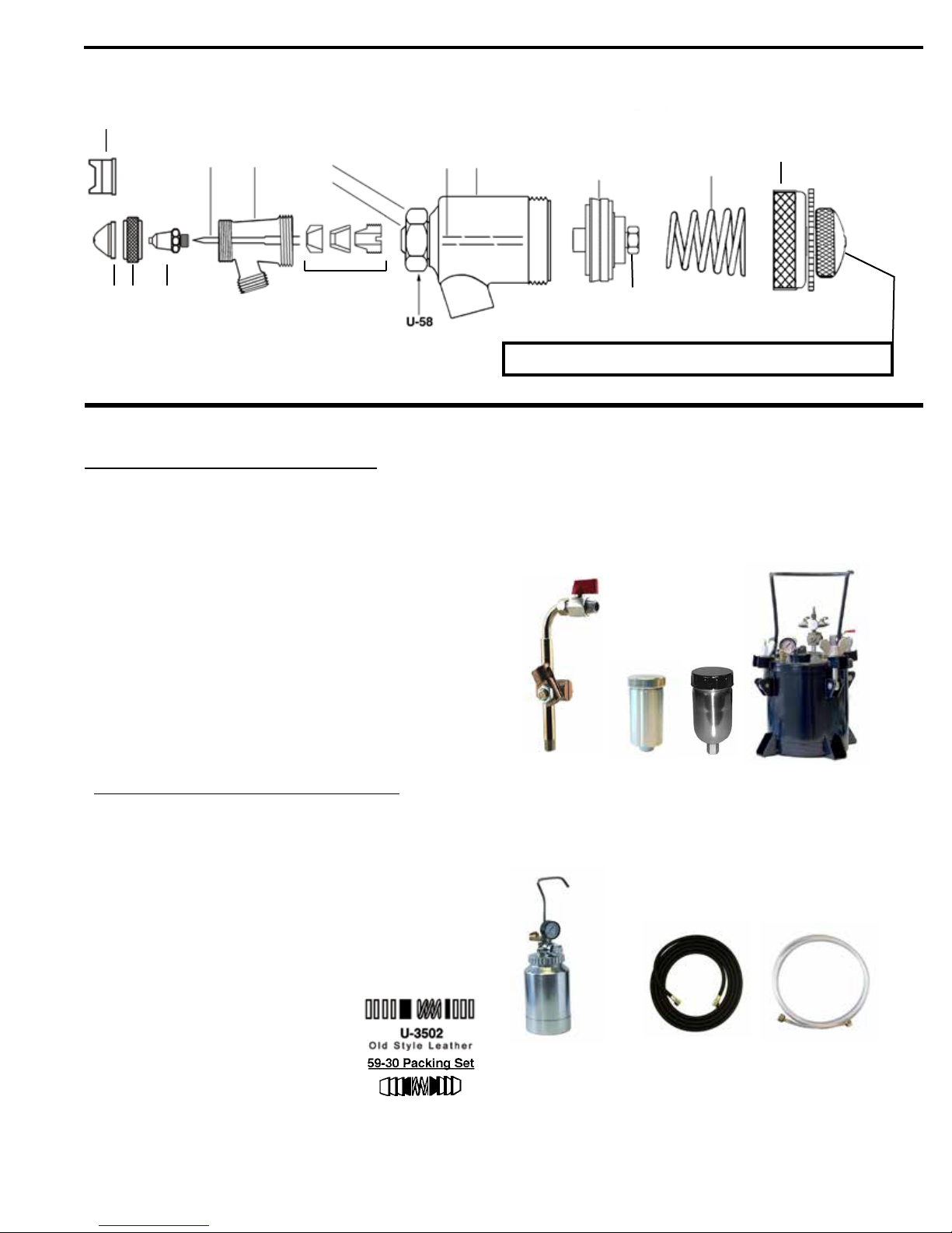
OPTIONAL ITEMS:
Size References: Tip and Aircap must match size
000 .014
0 .021
1 .028
2 .040
3 .046
U-3502 (Old Style) Leather Packing Set
59-30 (Old Style) PTFE Packing Set
A B C D
A. UM-20 Mounting Assembly
B. 27SC 3 oz. Gravity Cup
C. 28SC 8 oz. Gravity Cup
D. PT-25 Paint Tank (Less Agitator)
E F G
E. PT-64 2 QT Paint Cup W/ Regulator
F. HA-1/4-10 Fluid Hose W/HAC-1/4 Couplings
G. HL-3/16-10
10 FT Air Hose W/ 1/4 NPT Couplings
Page 2
Page 3

Paasche A-AU Spray Gun Accessories
Micro Extensions for coating inside small diameters. Will handle most light viscosity uids. AREH Extended Tip & AJR Extended Aircap
Body.
All AX Aircaps must use a Pressure Feed Cup or Pressure Tank to feed material being sprayed.
Always adjust atomizing air pressure higher than uid air pressure.
A-AU Accessories
79. AEN-45 Elbow
82. AN Nylon Washer
80. AEN-90 Elbow
AE- Extensions (For Fan and Round - Heads Only)
81. AE-3E Extension L/Needle
AE-6E Extension L/Needle
AE-18E Extension L/Needle
82. AN Nylon Washer
AX- Stainless Steel Extensions (AX - Aircaps & Tips Only)
AX Extensions Complete - Sizes: 3, 6, 12, 18, 24, 36 & 48
83. U-2831- Inner Tube (Select Size)
84. AUF-29 Nut
85. U-2832- Outer Tube (Select Size)
86. AX-1 Tip (Not Included with AX Extensions)
A-AU Extension Needles (Used with AE- & AX- Extensions)
87. A-AU-3 Extension Needle
A-AU-6 Extension Needle
A-AU-12 Extension Needle
A-AU-18 Extension Needle
A-AU-24 Extension Needle
A-AU-36 Extension Needle
A-AU-48 Extension Needle
AX Style Aircaps (Used with AX-Extensions Only)
88. AXR Aircap (External Round Pattern)
89. AXF Aircap (External Fan Pattern)
90. AXIF Aircap (Internal Fan Pattern)
91. AXIF-90 Aircap (Internal Fan Pattern)
92. AXIF-45 Aircap (Internal Fan Pattern)
93. AXIB Aircap (Spherical Pattern)
94. AXI-360 Aircap (Radial Pattern)
95. AXIF-90A Aircap (Internal Fan Pattern)
96. AXIR-15 Aircap (Internal Round Pattern)
97. AXIR-90 Aircap (Internal Round Pattern)
Page 3
 Loading...