

Page 1

V4000
Remote Video System
Control Center Guide
Installer Version
V4000 Control Center User Guide 1
Page 2

CONTENTS
Introduction................................................................................................. 4
Getting Started............................................................................................ 5
Installing Control Center...............................................................................5
Defining Screen Resolution and Colors........................................................ 6
Running Control Center............................................................................. 7
Calling a Site............................................................................................... 8
Playing Recorded Video Files....................................................................9
System Utilities......................................................................................... 12
Unviewed Files ......................................................................................... 16
On-Connection Functions........................................................................ 16
Video Windows........................................................................................... 16
Assigning Names to Cameras.................................................................... 16
Video Brightness Setting............................................................................ 16
Communication Information........................................................................ 17
View Port.................................................................................................... 18
Setting Remote Unit Parameters............................................................. 19
General Parameters................................................................................... 20
Advanced Parameters................................................................................ 21
Sensors and Alarms................................................................................... 23
Modem and Com Parameters..................................................................... 24
CCTV: Local Monitor Output....................................................................... 25
Event Relay................................................................................................ 26
PC System Settings.................................................................................... 27
Setting System Parameters..................................................................... 28
Communication and Modem Settings......................................................... 28
Security ...................................................................................................... 28
Sound......................................................................................................... 31
Callback...................................................................................................... 31
Printing....................................................................................................... 32
V4000 Control Center User Guide 2
Page 3

Folder......................................................................................................... 32
Bi-Directional (BIDI).................................................................................... 33
Additional Functions................................................................................ 34
Short Cut for Quick Dial.............................................................................. 34
Player Only Window................................................................................... 34
Create a New Shortcut............................................................................... 34
Answering Machine Defeat......................................................................... 35
General System Maintenance.................................................................. 36
Site List “Profile” Maintenance.................................................................... 36
Disk Maintenance....................................................................................... 37
Set Schedule.............................................................................................. 37
Appendix A - Direct Connection.............................................................. 38
Appendix B - Controlling Pan Tilt Zoom Cameras................................. 40
Appendix C - Working with Multiple Modems....................................... 43
Regulations............................................................................................. 444
© 2005 OzVision, Inc. All Rights Reserved.
Trademark Information
OzVision, OzLine, OzLine 4CS, OzLine 4VC, OzLine 12VC, OzLine 12CS
and OzVision Compatible are trademarks of OzVision, Inc. All other trademarks
are held by their respective owners.
V4000 Control Center User Guide 3
Page 4

Introduction
This guide provides step-by-step instructions for installing and operating
the Control Center software as well as a complete description of the
system’s capabilities and functions.
Once the Control Center software is installed, your computer becomes a
video monitoring station with the following functions:
Connect to any remote unit using the phone number and access
code and monitor video.
Digitally record the monitored video stream (including the time
and date) on the computer’s hard drive.
Retrieve and view video using advanced methods such as date,
time and site.
Print images on a standard printer.
Compare video streams coming from various sites, cameras,
dates and times.
Password protect the Control Center. Administrators can create
new passwords and change existing ones.
Control the image quality and video frame rate.
Remotely activate external devices directly from the Control
Center computer.
Monitor live video at remote site from a single camera or cyclic
scanning of a number of cameras.
Control Center can be initialized to open up as the top window
whenever a video stream is received from a remote unit regardless
of the program currently running.
Users can set pre- and post-alarm sequence durations.
The Ozline unit can call back to the Control Center and reverse
the phone charges.
V4000 Control Center User Guide 4
Page 5

Getting Started
Basic Hardware and Software Requirements
• CPU: Intel Pentium II 550 MHZ MMX or higher processor.
• Memory: 128MB of RAM
• Free Space: 5MB of available hard disk space.
• Modem: 33.6/56K
• Operating System: Windows 98/ME/2000 professional/ NT4/XP.
• Minimum screen resolution: 800X600, 24 true-bit colors.
Notes: 1. When using Windows 2000 you must define the modem
settings in your PC. Go to Desktop>My Computer>Control Panel>Modem.
Check the box, cancel the call if not connecting within 30 seconds.
2. The Windows installation procedure is slightly different in Window XP.
Installing Control Center
Follow the instructions in the window that opened when you inserted the
CD or:
1. Click on the Start button, at the bottom left corner.
2. Choose Settings from the menu.
3. Choose Control Panel from the Settings menu.
4. Double click the Add/Remove Programs icon.
5. Click Install to start the installation.
6. Insert the installation CD or diskette in the drive.
7. After the CD is in the drive, click Next.
8. The Windows installation program will search for
the installation program on the disc and display it in
the box marked Command line for installation
program.
9. Click the End button.
10. The Control Center Installation screen appears.
To cancel the installation, choose Cancel. To
continue the installation, choose Next.
V4000 Control Center User Guide 5
Page 6

11. Several files required for the installation process
will now be copied to your computer and the
Choose Destination Location window appears.
This screen is used to determine the directory in
which the Control Center is installed. It is
recommended that you install the program in the
default directory. The directory name appears in
the Destination Folder panel. After the destination
folder is chosen, click the Next button to continue
the installation.
12. Repeat the above procedure for the destination of
the data files. Click Next to select the program
folder window. The setup program will now copy
the program files from the installation CD or
diskette to your hard drive.
13. After copying all of the necessary files to your
computer, the Select Components screen
appears. Select one of the two following
checkboxes:
• Create a Shortcut to Control Center on My Desktop. Check
this box if you want to create a shortcut on your desktop.
• Run Control Center automatically upon startup. Check this
box if you want Control Center to load on start up.
14. Click Next to continue the installation. The
Information screen appears, confirming a
successful installation.
15. Click Finish.
Defining Screen Resolution and Colors
1. Right-click on an empty spot on the desktop.
2. Choose Properties from the menu. The Display Properties
window appears.
3. Choose Settings (at the top right side of the dialog).
4. Set the display area to 800 by 600 pixels or higher.
5. Set the Color palette to 24 true bit colors.
6. Set the Font size to Large Fonts.
7. Confirm the new settings by clicking Ok.
8. Restart the computer if necessary.
V4000 Control Center User Guide 6
Page 7
prop
Running Control Center
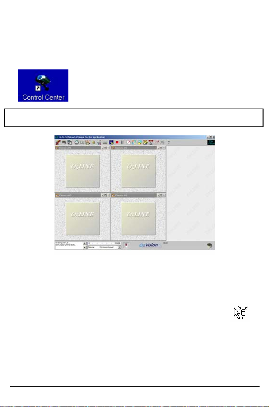
To run Control Center, double-click the Control Center shortcut on the
desktop.
The software is installed with default passwords: name = 1 password = 1
Main Screen
You can operate the software either from the pull down menus or from the
dedicated tool bar located at the top of the screen.
Several of the buttons in the tool bar perform two tasks. The mouse
If the setup program did not correctly identify the
modem or does not recognize the system profile, an
error message will appear on the screen. Click Ok to
open the System Settings dialog to configure the
erties.
pointer changes to a special icon when placed on top of the button.
Left clicking will operate the function. Right clicking opens an alternative
menu.
Pull down menus: to open and close the standard Windows pull down
menus click Ctrl + Shift + m.
V4000 Control Center User Guide 7
Page 8
rhe
c
hcd
ovato
e
Calling a Site
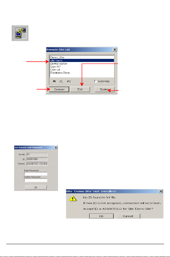
Click the Call button to open the Site List.
Note: To set up a new site, refer to PC System Settings
in the Setting Remote Unit Parameters section.
Search Site by
name.
Choose a Site and
click Connect (or
double click on the
site).
The Edit button will
open the site info
window for editing.
The System button
allows you to setup
system parameters.
The computer will call the site, and connect to the remote unit using the
site’s phone number (as explained in the Updating Site List chapter). The
phone number will appear in the Modem Dialog Box.
You will be asked to enter a Password. Enter the same Password in the
two fields and click Ok.
The unit saves the password and sends a
unique ID to the software. The software
identifies the new ID and asks you to
confirm it. Click Ok to accept the new ID.
Click Call again to disconnect and terminate the remote unit monitoring
session.
V4000 Control Center User Guide 8
Page 9
Playing Recorded Video Files
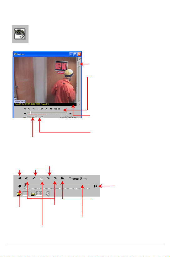
Clicking Play (top left) will open the stored video playback
window.
The vertical scrollbar adjusts the viewing
speed. While playing the video file, you
can slide the scrollbar to run the file faster
or slower.
The horizontal scrollbar represents the
position of the video image. Playing the
video file will cause the scrollbar to move
from left to right. Red tick marks appear
below the horizontal scrollbar in positions
corresponding to Pre- and Post-Alarm
frames. All non-alarm frames are marked
with gray ticks.
Video Information: Site name, camera
name (if defined), date, time, number of
frames and Zone number.
Opens the video in spread format allowing
To open a stored video file, first open the Site and
Files list by clicking the Open file icon on the left
corner of the playback window.
overview of events.
Jump to the first
frame of the clip
Skip to the
previously
recorded clip.
Stop the clip.
Play the file in reverse or
forward at the set speed.
Move one
frame Back or
Forward.
If the video clip contains an alarm event,
right-clicking the horizontal scrollbar will
display the frame that was captured at
the time of the alarm trip.
Skip to the next
recorded clip.
Jump to the
last frame of
the clip.
V4000 Control Center User Guide 9
Page 10
The Recorded Files List
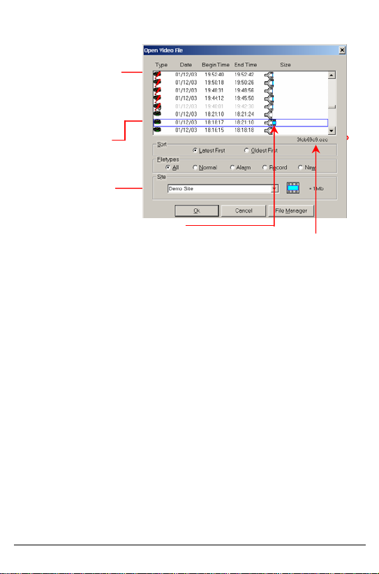
Type – This icon describes
the file type. A red diagonal
exclamation mark indicates
an alarm file.
Date, Begin Time, End
Time
Site Name
Size - Graphical
representation of the file
size. Each frame
represents 1MB.
File Name
File Management
Sort – Files are sorted by date and time. The most recently
recorded file appears at the top of the list, and the oldest file
appears at the bottom. Choose Oldest First to reverse the
order. Choose Latest First to return to the original sorting
order.
File Types – Displays the types of files in the list.
All – Shows all the files.
Normal – Shows only normal files. Does not display alarm
files.
Alarm – Shows only alarm files. Does not display normal
files.
Record – Displays files that have been downloaded from
recording units.
New – Shows unviewed files from all available sites.
Site – When the list is opened, the files from the first site in
the site list are displayed. You can choose another site from
the drop down list box to display files recorded from that site.
V4000 Control Center User Guide 10
Page 11
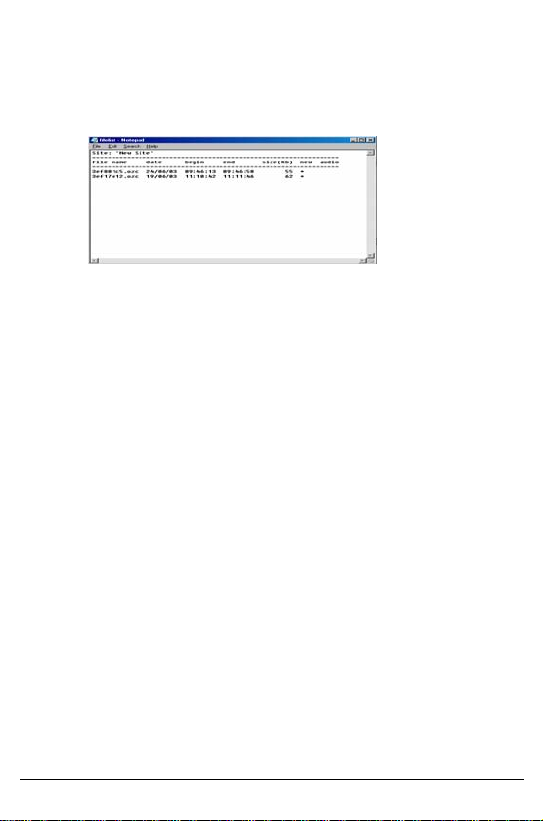
Export File List
Click the file and press the F4 button. The filelist-notepad screen will
open. You will now be able to export the file list to a text file.
Choosing Files to View
Double-click the file, or highlight the file and click Ok to open the file. The
first image will appear on the screen. The title bar will display the camera
number, as well as the date and time the image was received.
Deleting /Copying Files
Click File Manager. Choose the files to be deleted or copied by pointing
the mouse and clicking the right button. The selected files will become
red.
Click Delete or hit the Delete key to delete the selected files. Enter a valid
username and password to proceed.
Click Copy or F5 to copy the files to another directory.
Click F6 to move the files to another directory.
V4000 Control Center User Guide 11
Page 12
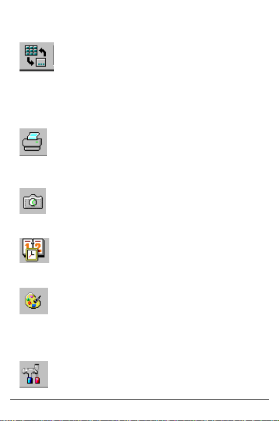
System Utilities
maximize the playback windows. A second click of this button will reverse
the operation.
You can set video windows to any size and location. To save these
settings, click the right mouse button and select Save settings. To use the
saved settings, select Use save settings in the pull down menu.
any printer connected to the PC including a FAX device. Use Print option
from the system menu to set print scaling. To print in the exact resolution
(no scaling), drag the video window to this button.
Bitmap, which can be transferred to a CD or any other removable storage
device.
(additional settings are available using set schedule). A right mouse click
will open a menu that can enable or disable the schedule function.
application that allows you to enhance or enlarge the picture in the active
window. You can also print or save it.
Every video window can be dragged and dropped by left clicking the
mouse.
Click Arrange window to minimize all live video windows and
The Print button enables you to print from any video window to
The Snapshot button saves the picture in the active window as a
Set up automatic communication using the Schedule button
Image enhancement. This button activates I-View, a graphical
This button opens the Systems maintenance utility that allows
you to edit and add remote sites as well as setting all systems parameters.
V4000 Control Center User Guide 12
Page 13
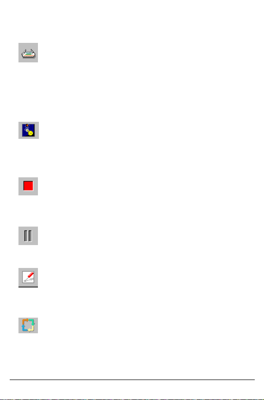
More information on setup functions are available in the Systems Settings
chapter.
This button opens the Site map with a left mouse click, or site text
information with a right mouse click (if a site map has been added).
To add a map to the site, insert a BMP file named ‘sitemap.bmp’ into the
site directory called Sites that is located in the main directory of the
Control Center software.
Right clicking the mouse will open a text file.
Arm/Disarm - this button will remotely arm/disarm the unit. When
armed, the background of the button will turn dark blue and a red light will
go on. Clicking again will turn the background light blue and the red light
will go off. This function can be password protected. (see Set password in
the systems parameter setting).
The Control Center automatically records all monitored video on
connection. This button will stop the recording of the video on the hard
disc. Click this button again to resume recording. This function can be
password protected.
During video transmission, you can freeze the video image by
clicking on this button, Click again to unfreeze the image. (This has no
effect on recording).
Set and Update remote unit parameters such as video quality,
communication parameters and all inputs and outputs from the Control
Center computer. (For more information, See the updating remote systems
parameters chapter).
To Cycle all cameras, click this button. Right-click to choose the
cycle plan of the cameras. The select camera window will open, check the
cameras you want to cycle and click Start.
V4000 Control Center User Guide 13
Page 14
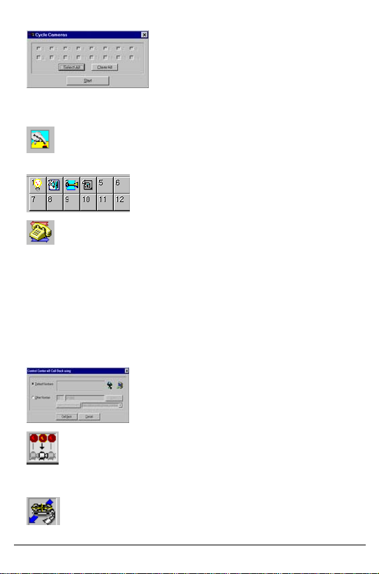
To stop cycling, click on any one of the opened video windows. While
Cycling, the unit will transmit full JPEG compressed frames
This feature is not active for the V4000.
The callback function allows you to reverse the phone charges.
This will open a window that will let you operate the call back function in
one of the following ways:
• Calling back to one of the two default phone numbers stored in
the unit
• Calling back to one of the numbers from the Callback list.
• Calling back by manually entering a one-time callback number.
After picking or entering a number to callback, simply click the call back
button in the callback window.
Auto camera-tracking alarm. The live camera on the
screen will automatically switch when an alarm occurs during
connection.
Download the recorded files from the unit.
V4000 Control Center User Guide 14
Page 15

This button activates the Auto help function, which provides
additional information on every function button or window in the Control
Center software.
Right click to open an additional information menu :
From this menu you can select:
About - information on the software version,
Command Line options
FAQ - answers to frequently asked questions
Customer support - how to contact the support department
Collate SW Report – Create a zip information file (that includes software
version and date, PC operating system, CPU, disk volume, log files and
sites list), which will provide technical support with all the information that
they need to troubleshoot any problems.
V4000 Control Center User Guide 15
Page 16
Unviewed Files
The Unviewed Files button appears at the bottom right
corner of the screen. Clicking this button will open a play
back window and a list of all unviewed files from all sites.
Sites are displayed in the field normally used to indicate file
size. (Unviewed files are files that have been received and
recorded but have not been played). The only way to move
a file from this list is to play it. It is then transitioned to the
All Files list.
Right click this button for the option to clear the unviewed
On-Connection Functions
When communication with a site is established - whether as a result of an
alarm or initiated from the PC - a few changes will appear on screen.
Video Windows
Video windows open automatically on-connection (the number of windows
is equal to the number of cameras at the site). To select a specific camera,
place the mouse on the camera window and left click.
Assigning Names to Cameras
While online, camera names will appear in the title bars of the camera
windows. When you run Control Center for the first time, the names will
take the default form - ‘CAMERA #’. Camera names can be changed by
double clicking the title bar and entering a new name. When done, hit
ENTER.
Video Brightness Setting
To change the brightness settings for each camera, move the cursor to the
bottom of each window and wait. A brightness scrollbar will appear. Drag
the scrollbar to change the brightness.
To set the new brightness as default, go to Save Video Brightness in the
Setting remote unit parameters.
V4000 Control Center User Guide 16
Page 17
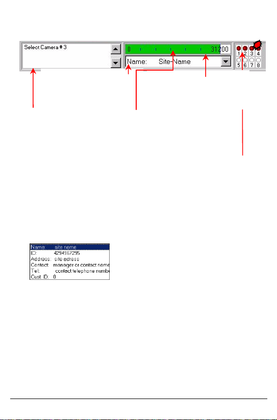
Communication Information
Connected Site Name.
Pressing the button on the end
will open the site information
window.
Modem status information.
When the software is in standby
mode (no communication) and
everything is Okay, the window
will show Waiting for Call
Site Information Window
Maximum Communication
speed is based on the quality of
the communication line
Real data transmission speed indicator.
Placing the mouse over this indicator
indicates transmission speed in frames per
second and in bits per second.
Alarm indicators at the connected remote site.
This display will appear only after connecting to a
site. The dark red LED’s indicate that the detector
is normal mode. When the detector changes
status, the LED will switch color to a bright light
red.
V4000 Control Center User Guide 17
Page 18
View Port
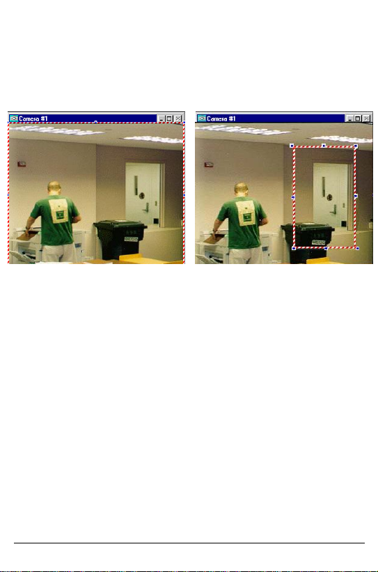
While connected to the unit, you can choose to view part of the frame and
receive live video only from this section. This will give you a higher frame
rate. To operate the View Port, right click anywhere in the video window.
A red/white/blue frame will appear.
Resize and move this
frame by using the mouse
To disable View Port, right click in the frame then click the left click
outside the frame and right click again anywhere.
Right click inside the frame to set
the View Port. The frame will turn
red and white only and the unit will
send updates only in the marked
area.
V4000 Control Center User Guide 18
Page 19

Setting Remote Unit Parameters
A few seconds after pressing the tuning button in the control
center, the remote setup window will appear.
You can temporarily set the image resolution. (High-resolution
delivers sharper images, with greater detail but slows the
transmission rate). The resolution changes made here are temporary
and the default parameters will be loaded on the next communication
To set, update or
change the remote
unit’s parameters, click
on the Unit Power-on
Parameters button.
To upgrade the remote
system’s firmware
directly from your PC
via the phone, click
Upload Firmware,
which opens the
upload window.
Temporarily sets the system mode to
Black & White or Color video.
To save the
camera’s
brightness setting
as the default.
• Type the source file
name or click
browse.
• Click Upload.
• After the transfer,
you will be
disconnected from
Press Ok to
confirm.
Enter the new
password, confirm
it and click Ok
The Set Remote
Password button allows
you to set or change the
remote password.
V4000 Control Center User Guide 19
Page 20
g
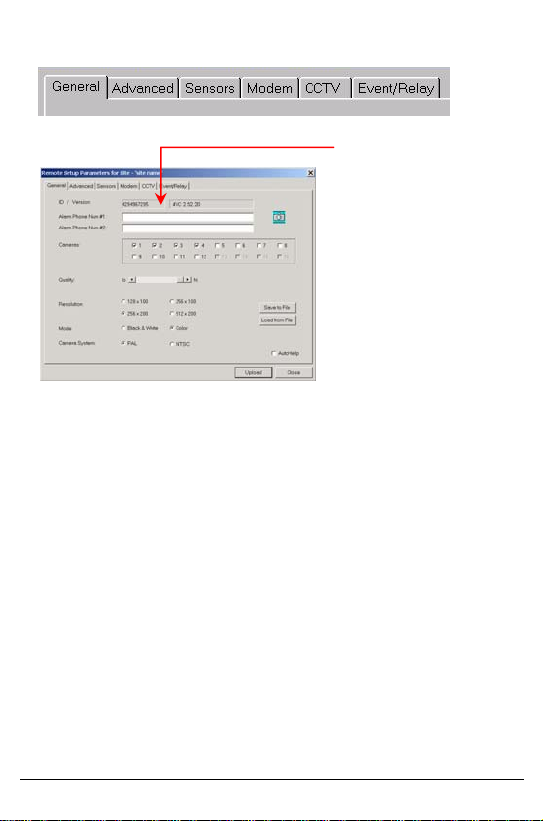
Remote units parameters are divided into six tabs:
General Parameters
Every remote unit has a
unique ID number. This
identification number will
appear in the ID and unit
version fields.
These parameters cannot
be chan
ed.
• Alarm Phone Num #1 / #2 – Use these fields to enter the phone
numbers that the unit will call in case of an alarm or a callback
request. If you have only one phone line, type the same phone
number in both fields.
• Cameras – Checks the active cameras at the remote site.
• Quality – Sets the compression ratio to the image quality you require.
Remember, high-quality images are transmitted slower.
• Resolution – Sets the resolution to the quality you require.
Remember high-resolution provides sharper images and greater detail
but slows down the frame rate.
• Black & White or Color- Selects black and white or color options.
• PAL/NTSC- Sets the camera’s format to NTSC or PAL.
*** This change will be effective only after rebooting the unit.
• Upload – Click this button to update the unit with the new parameters.
• Save to file – Click this button to save the new parameters to a local
file in your PC. You can later restore the values by reloading the
saved file.
• Load from file – Restores the last saved values.
• Close – Click this button to close the window without saving.
V4000 Control Center User Guide 20
Page 21
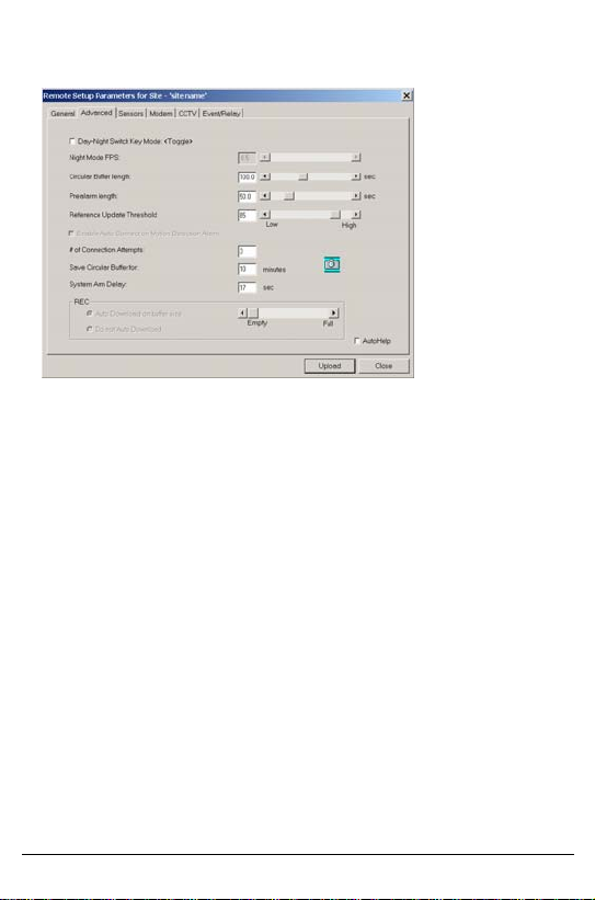
Advanced Parameters
• Day-Night Switch Key Mode - Arm the unit only by key switch
connected to the unit (toggle or push to change). This feature is not
active for the V4000.
• Circular Buffer Length – The length of the memory allocated to the
pre/post alarm.
• Pre-Alarm Length – The time span of the circular buffer allocated for
pre-alarm frames. The remainder of the circular buffer is devoted to
post-alarm frames. During a session triggered by an alarm, the unit
will first transmit the pre-alarm frames, then the post-alarm frames,
and finally, live video from the site.
• Reference Update Threshold – Defines the amount of change in the
video that will cause the unit to stop transmitting the streaming video,
transmit a new reference, and then continue to transmit the streaming
video.
• Number of Connection Attempts –Sets the number of tries the unit
will call the Control Center if the computer does not answer or the line
is busy.
• Save Circular Buffer for – Number of minutes that the unit will save
the frames stored as a result of an alarm. During this period no other
alarm input will be processed.
• System Arm Delay - The time in seconds between arming the system
to the time the unit will respond to alarms. This feature is not active for
the V4000.
• REC. – It is possible to store frames in units that have extended
memory (Drams units).
V4000 Control Center User Guide 21
Page 22

• Auto Download on buffer size – By choosing the Auto Download on
buffer size option, the unit will automatically download the recorded
frames to the Control Center. The download will begin when the buffer
is fully proportional to the location of the scrollbar.
Do not Auto Download – The unit will not download the recorded frames to
the Control Center until the user dials the unit and clicks Download From
the REC unit button
When the buffer is full the unit will delete the oldest frames.
Press the UPLOAD button to set and save the new parameters in the
remote transmitting unit.
V4000 Control Center User Guide 22
Page 23
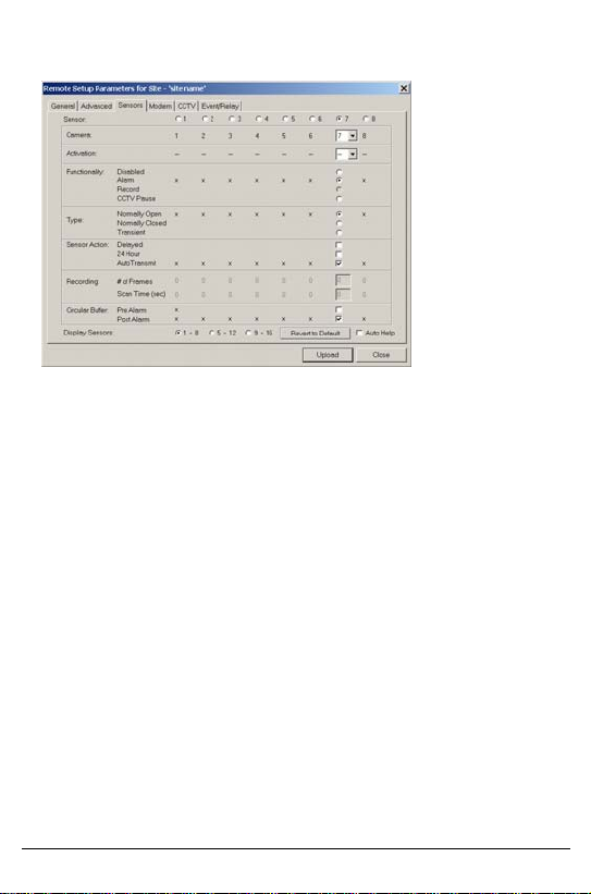
Sensors and Alarms
This tab
determines the
response of the
system to each
sensor.
Functions that
are not
available in the
unit you are
using will be
grayed out.
Available functions for each sensor:
9 Cameras - The camera will record or transmit video.
9 Activation - The output relay will be activated. This feature is not
active for the V4000.
9 Functionality - Functions and response to the sensor includes:
Disabled, Alarm , Record (no transmission), CCTV pause (stops
the cycling of the cameras in the video output on the unit).
9 Type - The type of sensor activation mode: normally closed,
normally opened or active on transient.
9 Sensor Action - Delay (delayed action), transmit or not transmitted to
the control center, active at all time, 24 hours a day even if the
system is not arm.
9 Recording - If you decided that this sensor will activate frame
recording, you can determine the number of frames to be recorded
and the time interval between the frames in seconds.
9 Circular Buffer – Sets whether the sensor will have pre and or post
alarm recording.
The revert to default button returns the unit to the default parameters.
Press the UPLOAD button to set and save the new parameters in the
remote transmitting unit.
V4000 Control Center User Guide 23
Page 24
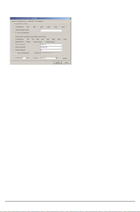
Modem and Com Parameters
• Internal Modem is Primary - Select whether the preferred
The communication parameters tab is
divided in half. The top section sets
the parameters of the internal modem.
The bottom section sets the
parameters of the external
communication device.
The unit can be connected to two
communication devices. It will answer
the first one that calls in and will dial
out using the one marked primary. If
this connection fails, the unit will
automatically try to call using the
secondary option.
communication method is primary or secondary.
• Limit Baud Rate –the baud rate can be lowered when
communication conditions or line quality do not support high-speed
transmission. Specific baud rate settings for an external
communication device can also be set.
• Additional Modem Initialization String – users can enter
additional commands to the modem within the text window.
• External Modem or Di rect Connection - this selection provides
the option of connecting the unit directly to a PC via RS-232
communication.
• Peripheral Device – see Appendix B.
• External UART – By selecting External UART as the primary
communication port, the internal modem will become the
secondary communication port. (Connecting to the Control Center
will first be attempted through the primary port. If that fails, an
attempt will be made through the secondary port).
• Country – Specify a country code if you are using an external
modem that supports this function.
• Answer After ____ Rings – Sets the unit to answer after a specific
number of rings. To operate the answering machine defeat
function, set the number of rings to “15” rings. ** See note on
setting the answering machine defeat function at the end of this
manual.
• Changing the baud rate of Com 2 (External UART) – If the
External UART is set as modem, you have to restart the unit (to
avoid unintentional lost of communication with External modem)
after changing the baud rate. If it is in Direct Connection mode,
restarting the unit is not necessary.
Press the UPLOAD button to set and save the new parameters in the
remote transmitting unit.
V4000 Control Center User Guide 24
Page 25

CCTV: Local Monitor Output
Simple three stage settings.
1. Select the cameras you wish to sequence and view on the
monitor.
2. Set the scan time in seconds.
3. Press Upload.
*** You can set the system to show only the camera you are positioning on
the monitor, by selecting only that specific camera in the CCTV setup.
***Temporarily stop the sequence of cameras by setting one of the inputs
as CCTV pause in the sensors setting page. This will allow you to connect
a switch to this input and stop the sequence when needed.
Press the UPLOAD button to set and save the new parameters in the
remote transmitting unit.
The V4000 is
equipped with a
video out (for a
local monitor)
and a built in
programmable
sequential
video switcher.
V4000 Control Center User Guide 25
Page 26
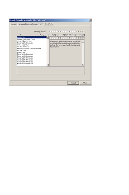
Event Relay
You can preset
the unit’s
response to
events.
The unit can
* Automatically
activate external
devices.
* Call the default
numbers.
For example: If you want the unit to detect video loss and then activate
number 2 (relay output), choose the Event Video loss and check the box
marked relay 2.
If you want to activate an external device that is connect to the unit, click the
Event, General Sensor Alarm, and check the output column that the
device is connected to.
By default, all relays are normally open. To change a relay to normally
closed, click the check box above each Relay #.
Press the UPLOAD button to set and save the new parameters in the
remote transmitting unit.
V4000 Control Center User Guide 26
Page 27
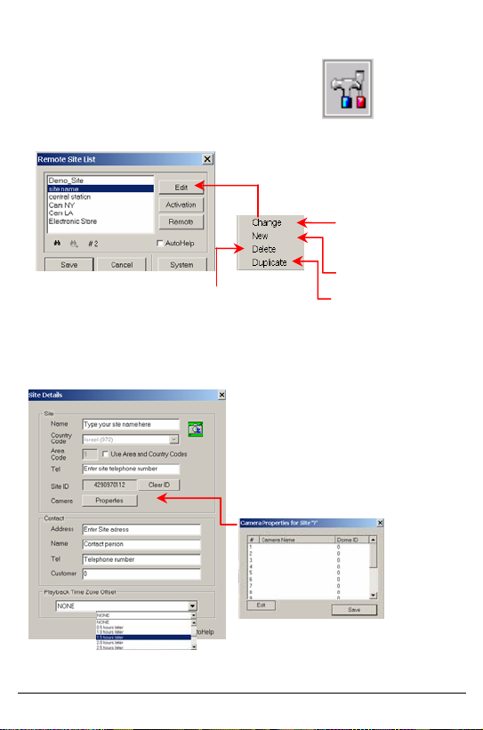
PC System Settings
To enter the settings press the Setup button.
To enter a new site or edit an existing one:
Click ‘Ok’ in this window, then
Delete a site from the list. Close
the site list editing button panel.
Click the Save button in the site list window to save
the new parameters.
The Edit button will open a pull
down list:
Every site includes:
Site Name
Unit telephone number
Address
Contact name
Contact telephone number
Customer serial number or ID
To Change site
settings, select a site
and press change
Enter a New site
Enter a new site
while duplicating the
information from an
existing site
To enable adding camera name and dome
ID offline, see appendix B (this can also be
done on-line)
V4000 Control Center User Guide 27
Page 28
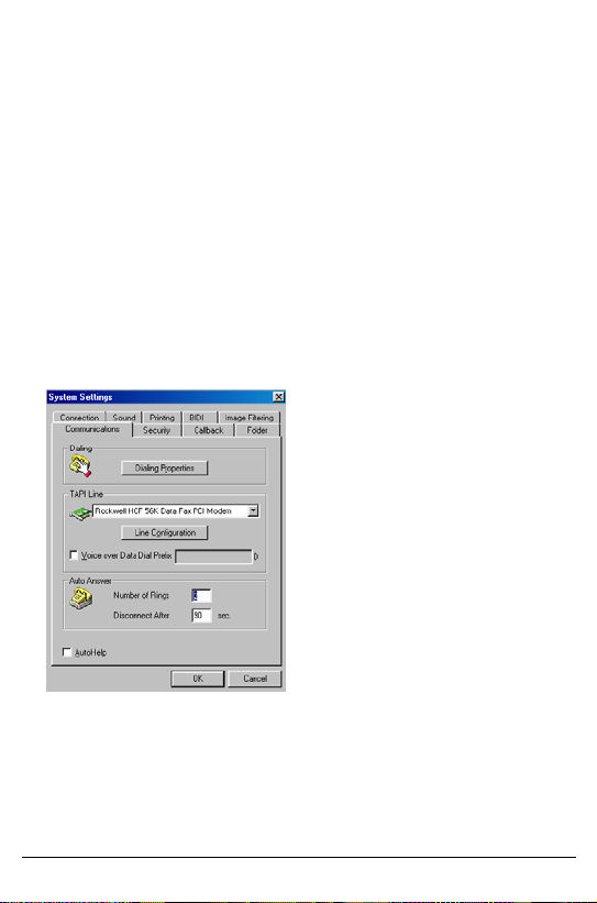
Setting System Parameters
To enter control center parameters click the System button in the site list
window.
The control center parameters are divided into sub groups:
½ Communication
½ Connection
½ Security
½ Sound.
½ Callback
½ Printing
½ Folder
½ Bi Directional
Communication and Modem Settings
The control center software runs
under Windows TAPI. The software
uses the modem according to the
default Windows settings.
The Dialing Properties and the Line
Configuration buttons open the
modem settings. Changes made here
are only temporary and the modem
settings will return to default after the
session.
If your PC is installed with more than
one modem you can select the
modem to be used by the control
center software.
Auto Answer – the auto answer function has two parameters:
Number of Rings – the number of rings before phone line pickup
Disconnect After – the PC will disconnect after the set time and only when
the remote unit calls your PC.
V4000 Control Center User Guide 28
Page 29
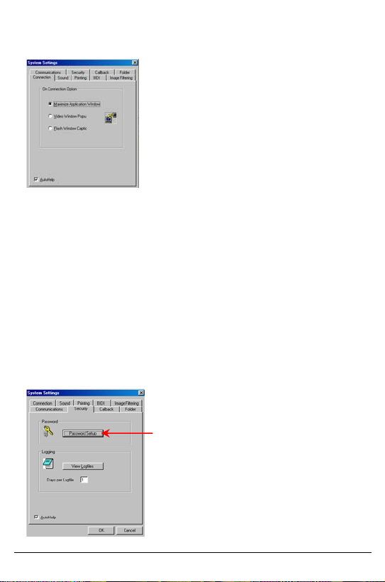
On-Connection
The control center software can
automatically respond to an incoming call.
It can either pop up on the screen above
all other open software windows in either
a maximum or smaller window, or it can
flash the software title button at the
bottom of the screen. Check the desired
Maximize Application Window (default)
The control center software will pop up in full screen if an alarm call has
been received and the software is activated.
Video Window Popup.
The control center software will open a small video window if an alarm call
has been received and the software is activated.
Flash Window Caption.
If an alarm call has been received and the software is activated in
minimized window format, the button at the bottom of the screen will flash.
A click on this button will open the software and maximize the window.
Security
To set passwords and levels of access for a User, press the Password
Setup button. You will be requested to enter a sysop name and password
in order to edit, add or remove a password.
Every operation of the control center software
as described in this manual can be restricted
by using a password.
By using passwords, operators can have
either a User or System Operator (Sysop)
level of access.
The default passwords are:
User - name = 2 password = 2
Sysop – name = 1 password = 1
V4000 Control Center User Guide 29
Page 30

Enter a Sysop name and password. If this is the first time, enter name and
password as ‘1’ and remember to remove this default sysop from the
password list.
The password user list will open.
Click Change, Add or Delete to set
up a user. A secondary edit
window will open allowing you to
enter a name, password and
define the level of security for this
user.
To activate the software’s password security you must select Password
Checking to be a choice other then none (the default). If Normal is
selected and the Password Event button is pressed, a new setup window
will open that will enable you to select specific operations as well as the
level of authorization.
To view the system’s log file, click View log files in the main security
window. The software saves two log files: Active and Previous. The length
of the log file is set in the edit window.
Select the level of authorization for
every function.
Set the timeout in seconds. You will
not be requested to enter your
password again during this time even if
you are entering a function that
requires a password.
Click Ok when done to save the new
settings.
V4000 Control Center User Guide 30
Page 31

Sound
The control center software
supports voice alerts from
your PC on events.
To disable all sound
functions check the Disable
Sound check box.
Three voice alerts are optional in the following cases:
1. When the PC receives an alert call.
2. When a connection from the PC to a unit is established.
3. When a scheduled connection from the PC is established.
Callback
This window includes your private
callback telephone book.
Use the Edit, Insert, Duplicate and
Delete buttons to update the book.
These numbers will be used when
activating the callback function.
V4000 Control Center User Guide 31
Page 32
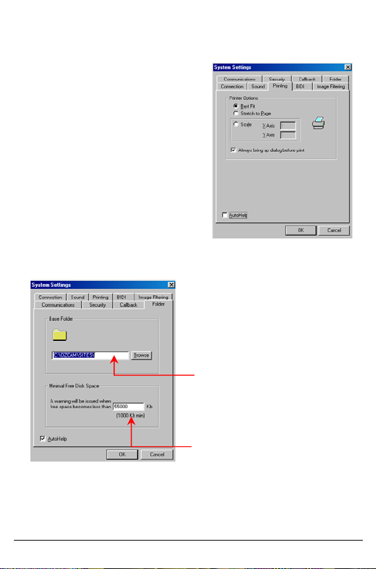
Printing
Set the printing parameters here to
assure the best output.
Best Fit is the default and is
recommended.
Stretch to Page will give you
the maximum print size.
Scale provides a manual
option to change the size of
the video print on the paper.
These settings will be saved and used
as defaults. If the default printer is a
fax, the image will be sent as a fax.
Folder
All recorded video and audio
received from sites is stored in
directories that are the same
name as the site.
All folders are located in one
main default directory called
SITES, which is in the systems
directory. This directory can be
moved to anywhere on your
hard drive or even to a network
disk by entering the exact path
in this box.
Minimal Free Space – You will
receive a warning when free
space becomes less than the
defined number of Kb.
V4000 Control Center User Guide 32
Page 33
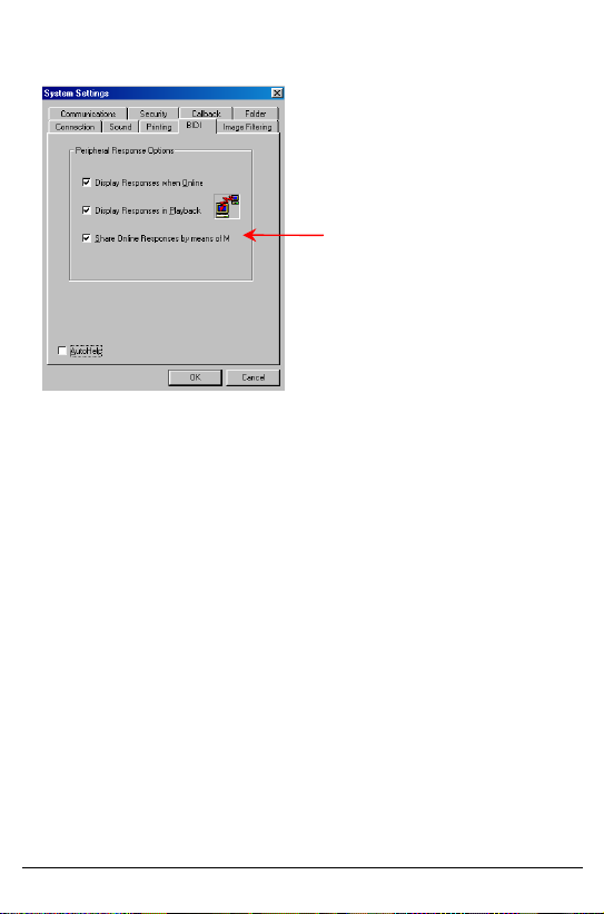
Bi-Directional (BIDI)
A shared memory space used
by Control Center and
residential software for
receiving and sending data to
peripheral systems connected
to the unit.
V4000 Control Center User Guide 33
Page 34

Additional Functions
Short Cut for Quick Dial
To create a quick dial icon so you can call directly from your desktop to a
desired site:
1. Click the control center icon.
2. Right-click Properties.
3. At the end of the target string, enter a space and then add the
site position # (This number is the site’s position in the site call
list - number one is the first and so on).
4. You can change the icon by clicking the Change icon button.
Player Only Window
To create an icon that will open a player only window, follow steps 1 to 3
as above in creating a quick dial icon and add a space and the letter “-P”
at the end of target string.
Create a New Shortcut
1. Click the control center icon.
2. Right-click once.
3. Select Create shortcut from the list.
4. To change the name of the new shortcut click the selected
icon’s name and enter the new name.
V4000 Control Center User Guide 34
Page 35

Answering Machine Defeat
To program the Answering Machine Defeat:
1. Set the unit to answer after 15 rings.
2. Press the UPLOAD button and disconnect.
3. Change the site’s phone number by adding ( ,,,, ? ) at the end of
the number.
4. Call the unit. At this stage you should hear 1-3 rings (if you hear
more than 3 rings, decrease the number of commas, if less than 3
rings are heard add more commas).
5. The Control Center will automatically disconnect, and will than
reconnect, whereupon the unit should answer immediately.
Note: Since the PTSN connection goes through a different number of
switchers depending on the geographic location, the number of commas
may differ. For further help and explanation contact our technical
support department.
V4000 Control Center User Guide 35
Page 36
General System Maintenance
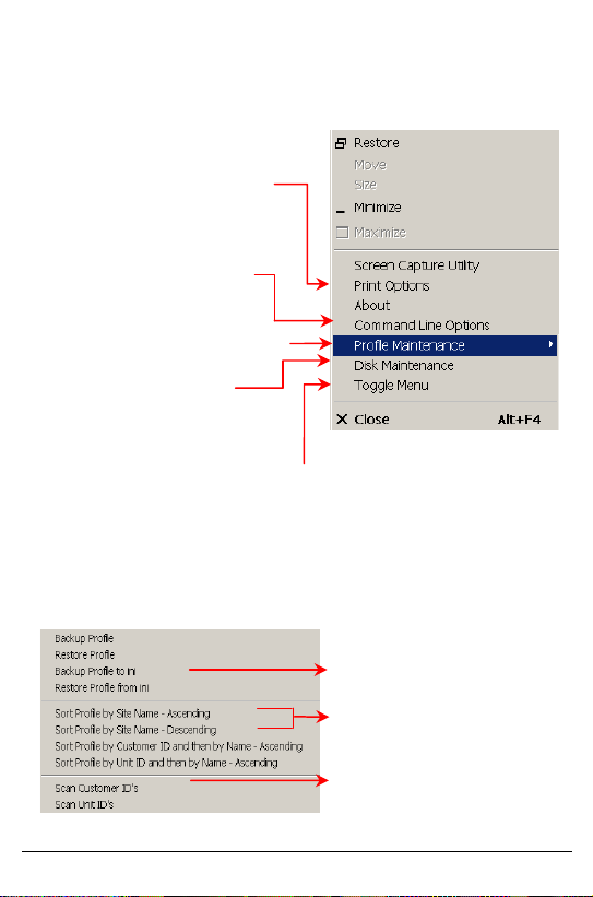
To open the maintenance pull down menu, click the Camera Icon at the
top left corner of the screen.
Print Options is a shortcut to
printing parameters as described in
the setting system parameters
section.
Command Line Options enables
specific software in the START
mode.
Profile Maintenance is used to
make back-up copies of all sites and
clients information.
Disk Maintenance is used
to auto-delete old files and obtain
disk capacity information.
Toggle Menu enables pull down menus.
Profile Maintenance
The profile is an encrypted data file containing information on all clients
and sites. If for any reason this file is ever damaged or lost you will lose all
information. It is recommended that you backup this file every few days.
Backup to ini saves the file in
text format. This file can be
printed and saved.
Sort Profile is used to resort
the site list.
Scan Customer ID’s verifies
that there are no identical ID’s.
V4000 Control Center User Guide 36
Page 37
Disk Maintenance
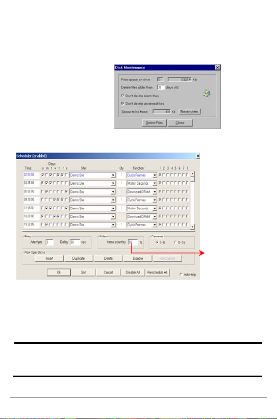
The disk maintenance tool is used to set up a FIFO file system. Old files
will be automatically deleted to free space for new files.
You can specify the
type and age of files
that will be deleted if
there is no space
available in the
computer hard disk.
Set Schedule
Click Insert to add a new scheduled connection. Enter the Time, Days and
Cycles from each camera. Then select the function to be preformed. Cycle
frames will transmit and record single frame/s from every camera. Motion
seconds will transmit and record streaming video for X seconds from
every camera. Download DRAM will download the recorded video in the
unit. If no camera was chosen, no call will be initiated.
Note: the PC will not call a site while you are using the PC. The PC must
be idle for at least 30 seconds. If Control Center failed to connect to the
site a failed dialog box will appear.
Control Center can
automatically call
sites at predefined
times and days.
These calls will
trigger the unit to
perform a defined
task. Control Center
will record those
frames for future
playback. If low
communication is
expected, increase
this value.
V4000 Control Center User Guide 37
Page 38
Appendix A
Direct Connection
For a direct connection you must connect a Null Modem Cable (Serial
Cable) between the external port in the unit (see the following diagram)
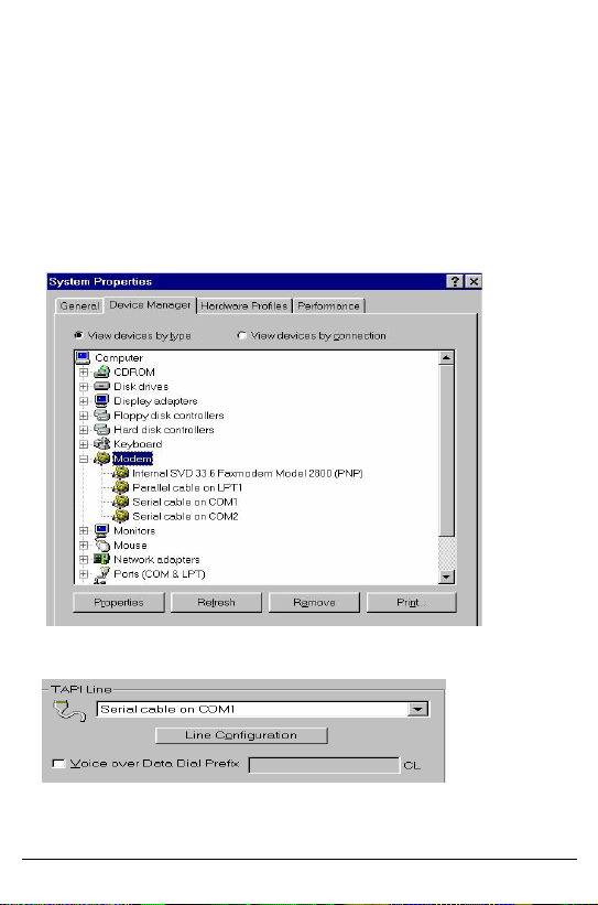
and the RS232 port of the PC. In Control Panel>System>Device
Manager> Modems check that you defined a Null Modem Cable as one of
the modems
The device manager should look like this:
In the Control Center software, make sure that you are working with a
Serial Cable instead of a modem, in Setup/System TAPI line.
Save the changes and click the Call button.
V4000 Control Center User Guide 38
Page 39

If the Baud Rate (the maximum speed parameter) is different between the
PC and the unit, the software will try to find the baud rate from 1200 –
115000. If communication is still not successful, please check the ports
and cable on your PC.
Note: If you try to connect directly to the unit that supports an RS485 port,
the Direct Connection operation will fail because the PC port works with
RS232 while the unit uses an RS485 port. They will not “understand” each
other.
V4000 Control Center User Guide 39
Page 40
Appendix B
Controlling Pan Tilt Zoom Cameras
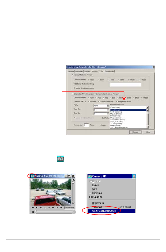
Each type of Dome camera has its own protocol so check that the
Control Center software supports the Dome you are using. If the unit
at the site has a PTZ control camera connected, you can control it
directly from the live video window.
1. Dial the unit.
2. Click Tuning>unit
power-on
parameters>
modem screen.
Choose the required
protocol by clicking
Peripheral Device in
the modem tab
screen and define
the baud rate of the
Dome (usually
between 2400 to
19200).
3. Click Upload. Disconnect and restart the unit.
4. Dial the unit again to receive video from the Dome.
5. Right Clicking the
button will open the following window.
V4000 Control Center User Guide 40
Page 41
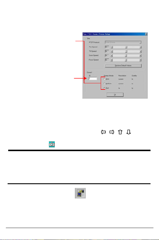
6. Set the speed of the Dome camera. If using a dry connect
controlled motor, check the Implement Pan Tilt Zoom check
box.
7. Sweep Mode,
Resolution and Quality
settings determine the
frame rate and quality
during Dome camera
movement.
8. Type the ID number of
the Dome camera in
this box. Check with
your vendor for the
correct Dome ID. (The
Dome ID should be one
to three digits.) Click
Ok to save the new
parameters.
9. Moving the mouse in the video window changes the mouse
icon into 9 different operation options, depending on the
location on the window. The operators are
in
the left right top and bottom of the picture. Zoom and focus are
in the corners.
Note: If the Dome works with the RS485 protocol, connect the Dome to
the unit to the TxDA and to the TXDB pins 1(-) and 2(+). If the Dome is
working with the RS232 protocol, connect the Dome to pins 2 (RX) and 3
(TX) in the RS232 plug of the unit. There is an option to install an RS232
to RS485 converter. For details, please contact the unit supplier in your
region.
10. Test Dome – Right click the button opens a Test Dome
window:
V4000 Control Center User Guide 41
Page 42
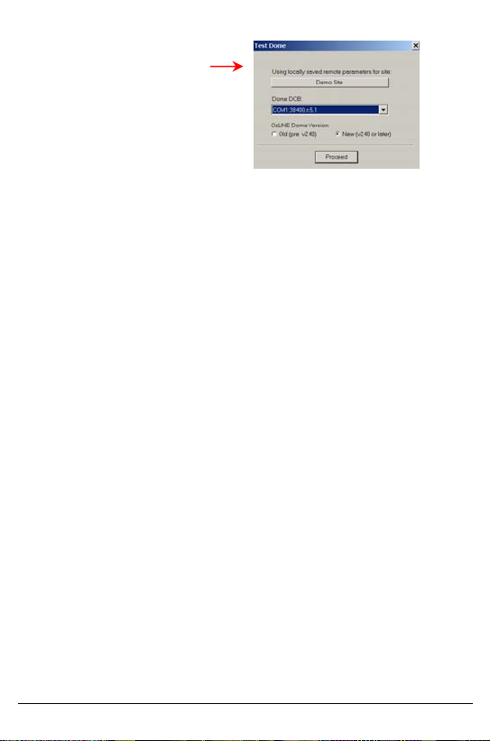
This feature enables
installers to test the
installation of the dome
camera before connecting it
to the OzLine unit.
V4000 Control Center User Guide 42
Page 43

Appendix C
Working with Multiple Modems
To work with a single modem double click the Control Center shortcut.
To add a second modem (8 modems and up to 64MB modem memory are
available) to the Control Center software (Client running):
1. Copy the shortcut of the Control Center software on the
Desktop:
• Right-click the Shortcut.
• Drag and drop it to another place on the Desktop.
2. Change the properties of the new Shortcut:
• Right-click the new Shortcut.
• Choose Properties.
• In the Target field, add a space and then “–L1” after exe
(Ozcam.exe -L1).
• Click Ok to save the changes.
• Double click the new Shortcut to run the Control Center
software.
3. Define the second modem:
• Click the System Setup button.
• Click the System button.
• Choose System (client) option. In the Communications
section choose the second modem in the TAPI line field.
• Click Ok to save the changes.
4. To define another modem (another client) repeat steps 1 to 4,
but in step 2, type “–L2” (or –L3 or –L4 etc.) instead of –L1.
5. You can define local parameters in the Control Center
application that is running with “–Lx” such as the Modem or On
Connection Option in the Connection section. Editing all
common data, Sites List and Scheduling is done only from the
first instance of Control Center (-L0) or by pressing on the
server when updating from additional modems.
V4000 Control Center User Guide 43
Page 44

Regulations
Note: This equipment has been tested and found to comply with the limits
for a Class B digital device, pursuant to part 15 of FCC rules. These limits
are designed to provide reasonable protection against harmful interface in
a residential installation. This equipment generates, uses and can radiate
radio frequency energy and, if not installed and used in accordance with
the instructions, can cause harmful interface to radio communications.
However, there is no guarantee that interface will not occur in a particular
installation. If this equipment does causes harmful interface to radio or
television reception, which can be determined by turning the equipment off
and on, the user is encouraged to try to correct the interference by one or
more of the following measures:
− Reorient or relocate the receiving antenna.
− Increase the separation between the equipment and receiver.
− Connect the equipment into an outlet on a different circuit than
the one that the receiver is connected to.
− Consult the dealer or an experienced radio/TV technician for
help.
This product complies: EMC;89/336/EEC as amended by
92/31/EEC and 93/68/EEC
Harmonized Standards to which Conformity is declared:
EN 55022:1994; EN 50082-1:1992
We hereby declare that the equipment conforms to the above directive and
standard.
V4000 Control Center User Guide 44
Page 45

 Loading...