

Page 1
PRODUCTION YEAR:
SERIAL NO:
PRODUCTION SITE : Beylikdüzü Eski Hadımköy Yolu 1.Km Büyükçekmece İstanbul/TÜRKİYE
Phone : 0090 212 886 78 00 (8 Hat-Lines) Fax : 0090 212 886 66 29
Published on : 01.01.2013
VER:V13.01 1/16
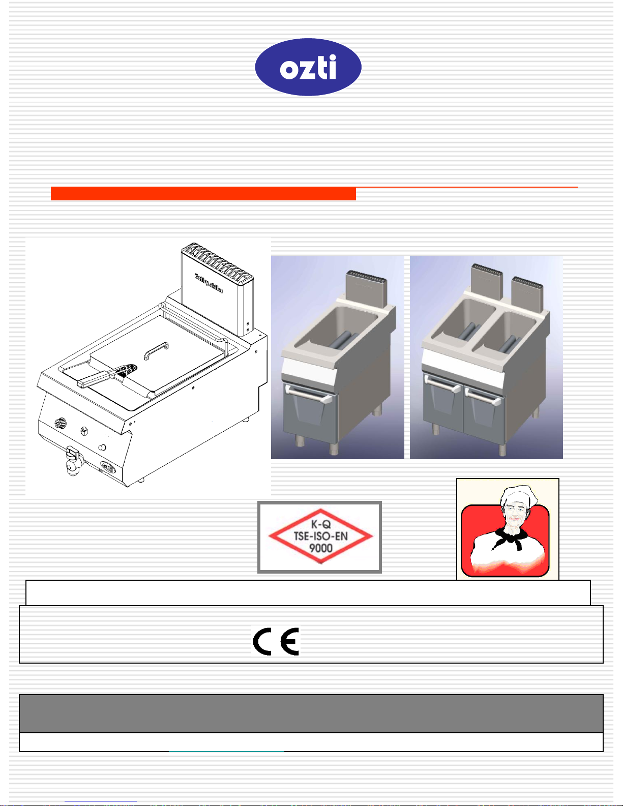
FRYER (GAS)
USER’S MANUAL
Our website: www.oztiryakiler.com e-mail: [email protected]
MANUFACTURER : ÖZTİRYAKİLER MADENİ EŞYA SAN. VE TİC A.Ş.
- 1783
Page 2

TABLE OF CONTENTS
2/16
PAGE NR. TOPICS
1 COVER PAGE
2 TABLE OF CONTENTS
3 INTRODUCTION
4 TECHNICAL DATA
5 MAIN DIMENSIONS AND WARNING SIGNS
6-7 SAFETY DETAILS
8 TRANSPORTING AND MOVING
9-10 INSTALLATION OF THE APPLIANCES
11 CONTROL BOARD
12-13 OPERATION OF THE APPLIANCES
14 CLEAN-UP AND MAINTENANCE
15 CHANGING THE GAS SYSTEM
16 TERMS OF WARRANTY
Page 3

INTRODUCTION
☞ Please read and ensure that your operation personnel also reads this user’s
manual care fully before installing and using the appliance. If the appliance is
operated without reading the user’s manual, the appliance will not be covered
by the warranty.
☞ The manual containing information about installation, usage and maintenance
of our product you purchased should be read carefully. Please ensure that
power supply connections to the appliance are already installed by qualified
personnel according to local legislation, before our authorized service
personnel arrives for the installation of the appliance.
☞ If you are confused or you don’t have enough information
please get in touch with authorized service by phone.
☞ Please keep in mind that, if the service personnel is delayed
at your site, related expenses and delay costs will be charged to
you on hourly basis.
☞ We hope that you will get the best performance from our product…
Dear User,
Thank you for purchasing our appliance and for your reliance upon our
company. Our appliances are used in professional kitchens in 75 countries.
Our appliances are produced in compliance with international standards.
Important notice: Please read and ensure that the users read this user’s
manual in order to achieve the desired performance in line with your
expectations and to use your appliance for long years. Please take the
warnings mentioned above into consideration before calling for service...
3/16
Page 4
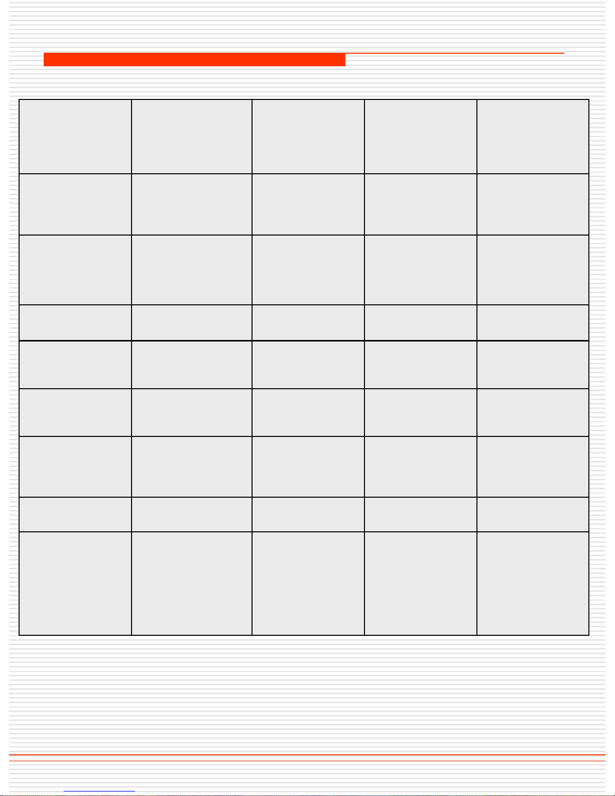
TECHNICAL DATA
4/16
YOUR
PRODUCT'S TYPE
☞
OFGI 4090
OFGI 8090
OFGI 4070
OFGI 8070
MAIN
DIMENSIONS
(mm)
400X900X 850 800х900х 850 400x700x850 800x700x850
HEAT POWER
(KW) (H
İ
) ΣQ
N
22 2x22=44 10 2x10=20
TYPE
А
1
А1 А1 А1
GAS INLET (inch)
½” R ½” R ½” R ½” R
THERMOSTAT
(ºС)
110-190 110-190 110-190 110-190
SAFETY
THERMOSTAT
(ºС)
230
230
230
230
CAPACITY
22 22+22=44 12 12+12=24
FRYING
CAPACITY
Maximum
(kg/batch)
3 6 2 4
Page 5
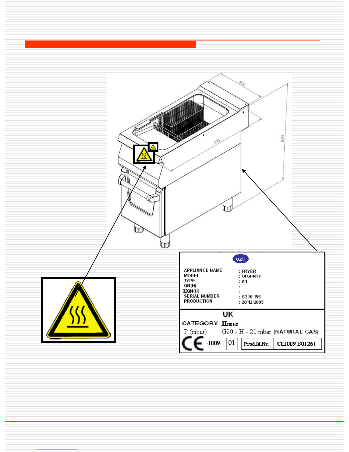
MAIN DIMENSIONS AND WARNING SIGNS
Figure 1: Main Dimensions and Warning Signs
5/16
HOT SURFACE
SAMPLE LABEL
☞ MODEL OFGI 4090
Page 6
SAFETY DETAILS
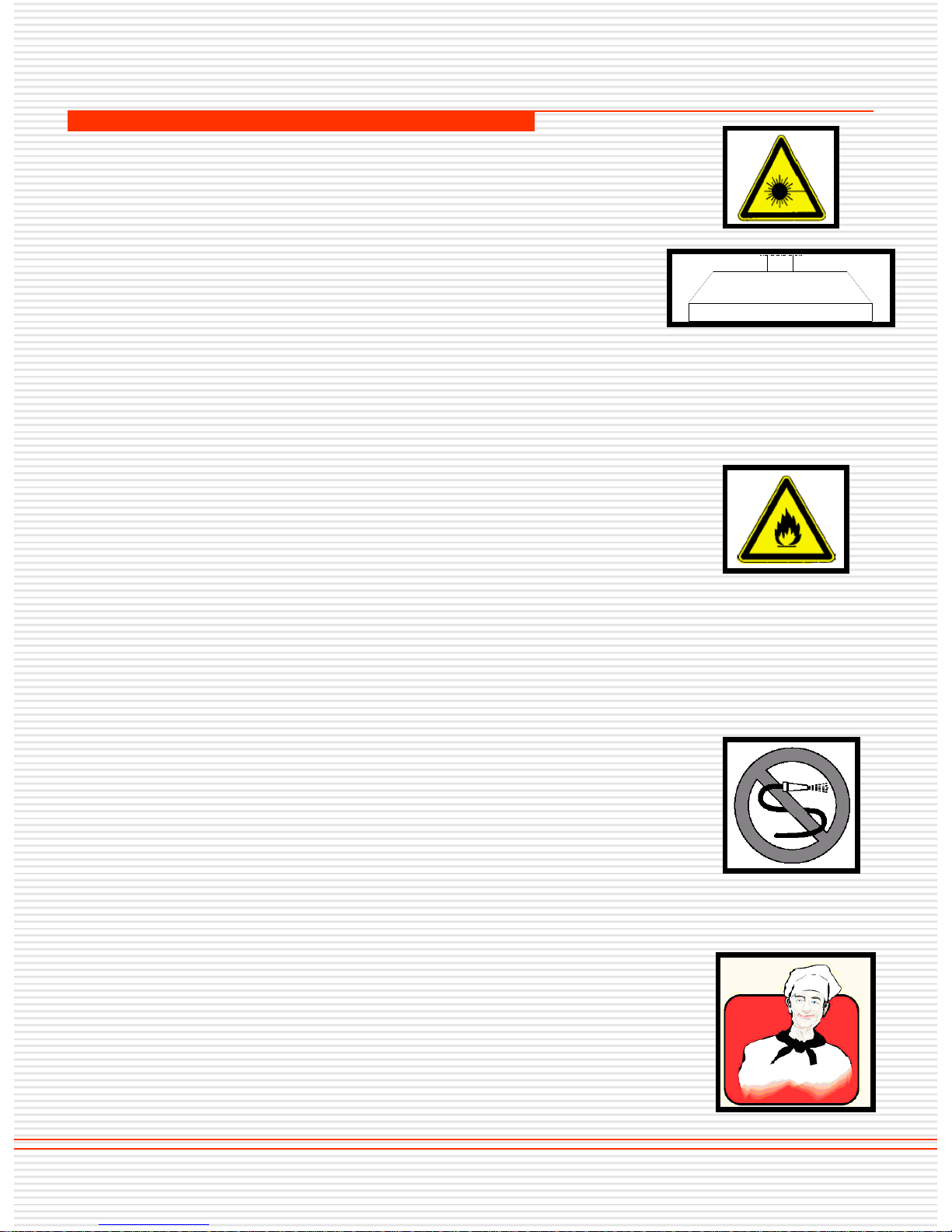
☞ Do not leave the appliances under direct
sunlight.
☞ The appliances should only be operated
under a chimney hood.
☞ If the appliances is operated using a LPG
gas cylinder, the distance between the
appliances and gas cylinder should be
minimum 50 cm.
☞ Any kind of flammable solid and liquid
material (cloths, alcohol and derivatives,
petrochemical products, wooden and plastic
materials, cutting blocks, curtains etc.)
should never be held near the appliances.
☞ You can use this appliances simultaneously
together with other products of ours.
☞ Do not clean up the appliances with pressure
water
☞ This appliances should be installed in line
with effective regulations and only be
operated in well ventilated places. Please
refer to the instructions before installing and
operating the appliances.
☞ This appliances is designed for industrial
use and should only be operated by personnel
trained according to this manual.
6/16
Page 7
SAFETY DETAILS
☞ The appliances should not be handled
by unauthorized persons except for the
manufacturer or authorized service.
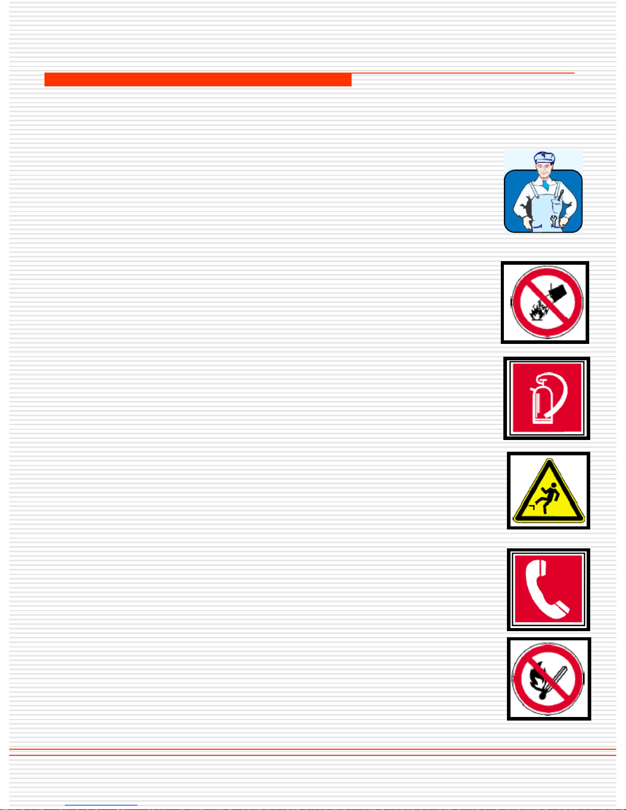
☞ In case of fire or flame in the area where the
appliances is operated, act without panic, close
gas valves, turn off the power switches and
use a fire extinguisher. Never use water to
extinguish the fire, water will cause the fire to
spread more faster.
☞ Oil spilled on the ground during use must be
wiped away. Otherwise it will cause the ground to
be slippery.
☞ Gas smell indicates gas leakage. In this case
close appliances valve and main gas valve,
open the doors and windows, do not use
sparkling material like power switches. Please
call for our service swiftly.
7/16
Page 8
TRANSPORTING AND MOVING
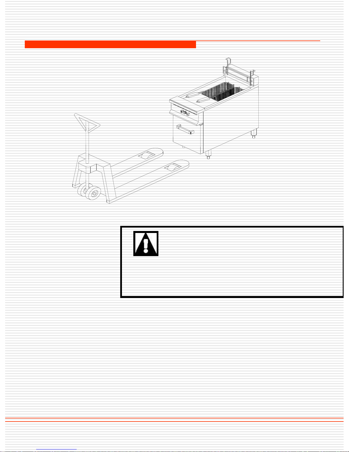
☞ The 900 series should be moved with the help of
vehicles like fork lift.
☞ The appliances should be transported by placing the
feet of the fork lift under the appliances.
☞ If the transported distance is far, the vehicle should be
moved slowly and the appliances should be fixed on
palette or supported in order to prevent jolt.
☞ Do not hit or drop the products when moving.
CHANGING THE LOCATION ;
Vehicles installed by an authorized
service CANNOT BE MOVED
ELSEWHERE, ITS CONNECTION
HOSES AND CABLES CANNOT BE EXTENDED OR
REPLACED except by an authorized service.
8/16
Page 9
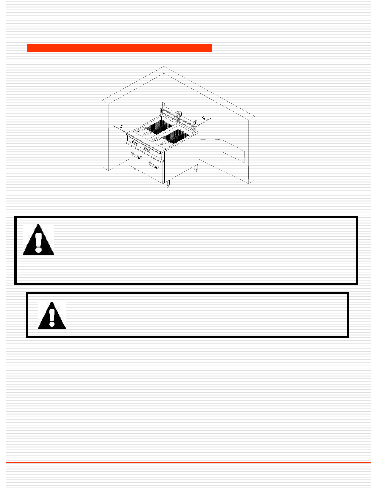
If this appliances located near to any wall, separation, kitchen
furniture, decorative coating etc. the distance in between
should be min.20 cm. and if those are coated with fireproof heat
insulating material, the distance should be min. 5 cm. It is strongly
recommended that fire safety protection instructions are observed.
INSTALLATION OF THE APPLIANCES
☞ The feet of the appliances should be height adjusted and the
appliances should be ensured to operate in a leveled position.
☞ All of the gas connections of the appliances should complying with ISO
7-1 or ISO 228-1.
☞ Gas connections of the appliances should be carried out by an
authorized service personnel, only after controlling its label according
to gas type and pressure. Connections of different type and/or at
different pressure should not be done.
9/16
All of the items mentioned below in connection with the
installation of the appliances should be carried out by
authorized service personnel.
THE DISTANCE BETWEEN THE GAS CYLINDER AND THE APPLIANCES SHOULD BE MIN. 50 cm.
L
P
G
50
Page 10
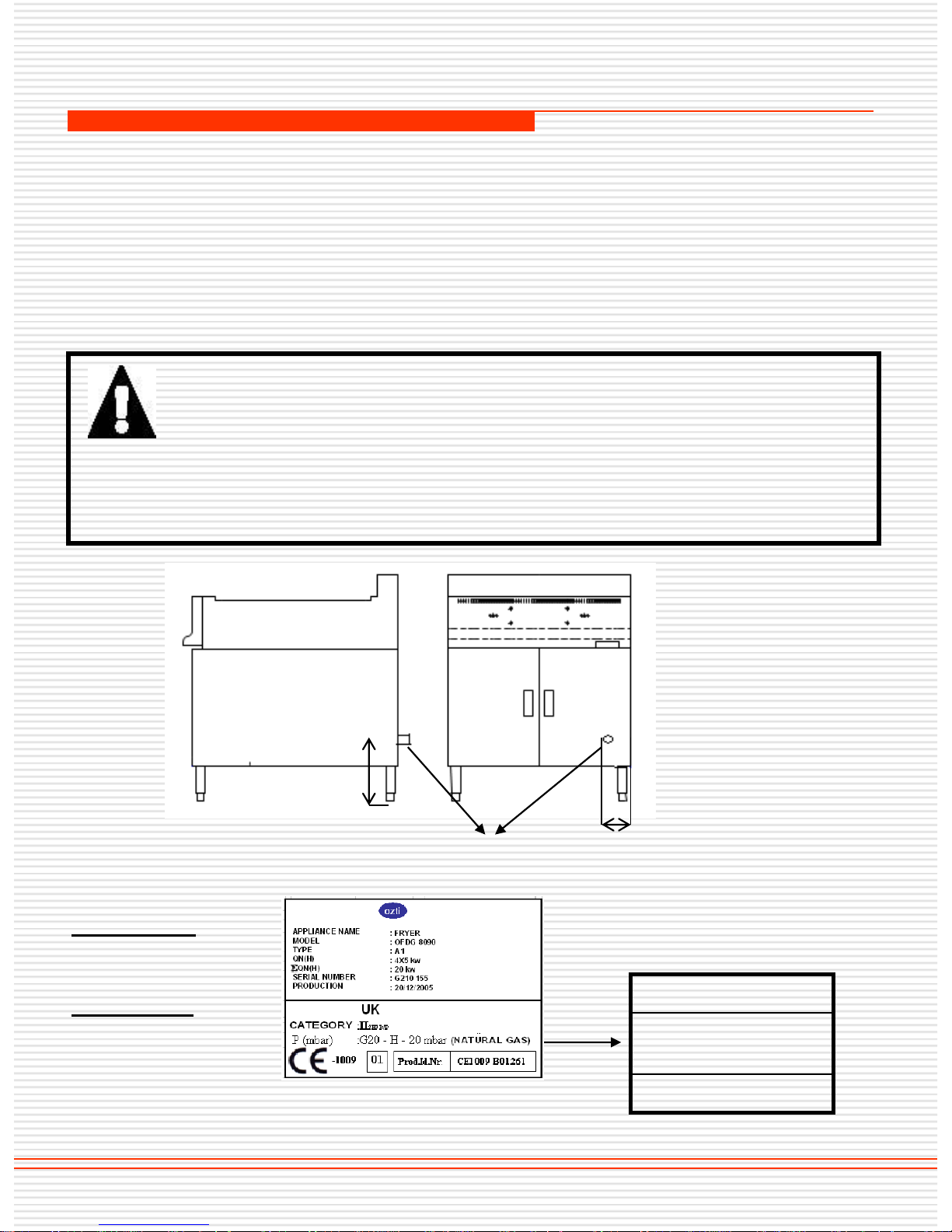
☞ Gas connection inlet dimensions are defined at the table of TECHNICAL
DATA.
☞ After the appliances is connected to the system gas usage should be
checked with soap bubble method.
☞ Air inlet adjustment is done by the authorized personnel if necessary, after
checking the appliances.
INSTALLATION OF THE APPLIANCES
10/16
☞ Nominal power of the device cannot be changed upon
customers request. Any modification made on valves and
injectors, leaves the device out of warranty coverage.
☞ Do not let use spare parts not being original. Installing spare
parts not supplied by our company, will leave the device out of
warranty coverage.
GAS CONNECTION DIMENSIONS
GAS USED
G20 (NETWORK
NATURAL GAS)
G30 (LPG GAS)
OFGI 40X90
A: 220 mm
B: 30 mm
OFGI 80x90
A: 185 mm
B: 125 mm
A
Gas Inlet
B
Page 11
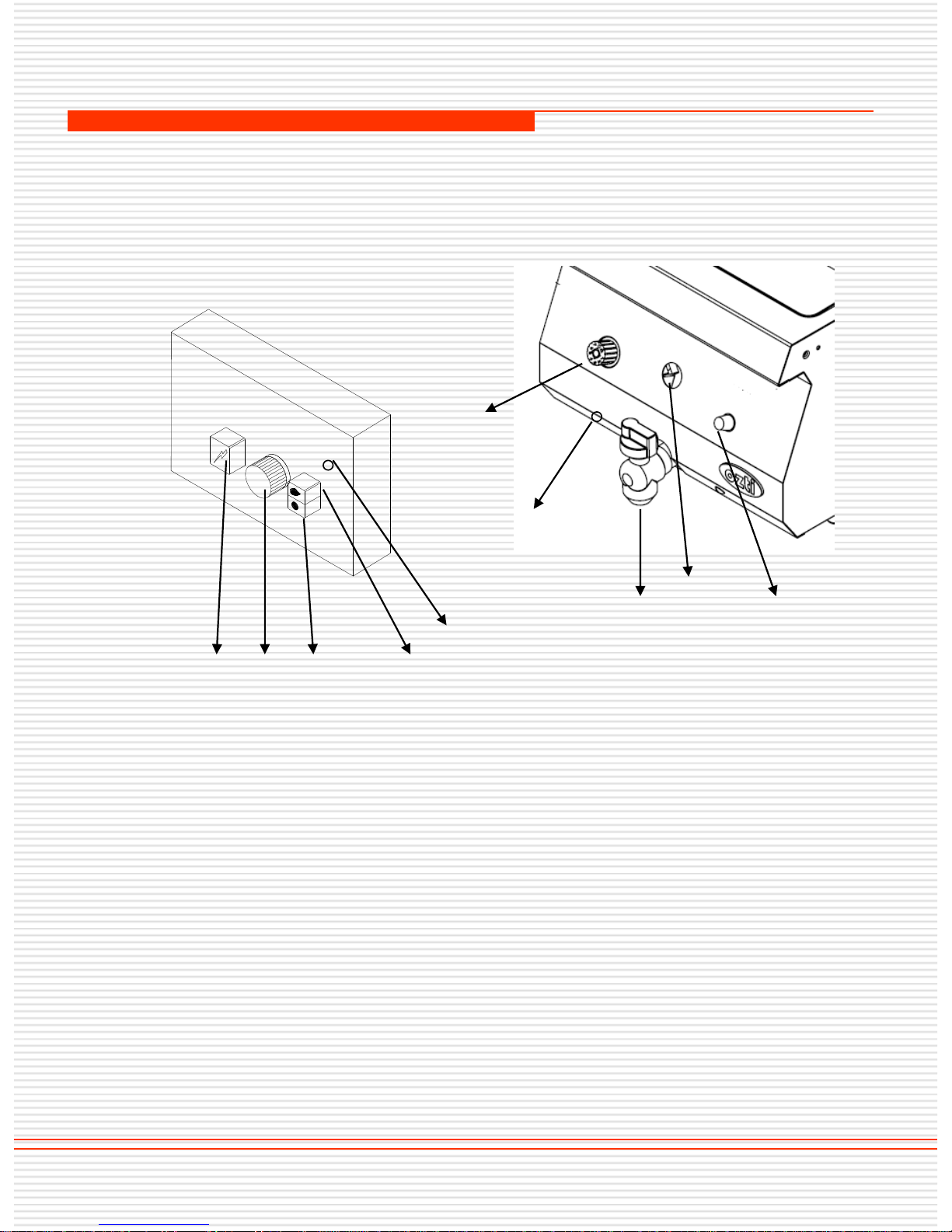
CONTROL BOARD
☞ 900 SERIE
11/21
A
C
B D
E
OFGI 4090
OFGI 8090
☞ 700 SERIE
OFGI 4070
OFGI 8070
A
B
F
G
E
A- THERMOSTAT ADJUSTMENT VALVE
B- LIGHTER Piezo (Electrical optional)
C- SHUT OFF KNOB
D- IGNITION BUTTON
E- LIMIT THERMOSTAT RESET BUTTON
F- DRAIN TAP
G- FLAME OBSERVATION HOLE
Page 12
OPERATION OF THE APPLIANCES
2. Before initial use of the appliances, outer surface and inner vessel should be wiped with
a cloth soaked in warm water and soap.
3. The appliances should be located under a filtered chimney hood connected to fresh air
channel.
4. The oil used within the fryer should be changed regularly depending on frequency of
usage. In this respect FOOD REGULATIONS should be taken into account.
NOTE: Do not use except purpose of use. The appliances should be operated by a
qualified personnel knowing safety terms and technical specifications and who has read the
instruction manual.
CAUTION:
* Oil level should never be below the minimum oil level.
Oil at lower levels bears the risk of inflaming.
* Oil level should never be above the maximum oil level.
Oil at higher levels bear the risks of running over and spilling.
* Do not operate the device without oil inside.
B. OPERATION OF THE DEVICE
1. IGNITING PILOT LIGHTER :
Turn ignition button (D) continuously, after waiting for 15-20 seconds (a time period
allowing the air in the gas pipes to exhaust and the gas to flow inside), igniter (B) should be
pressed to ignite. So pilot lighter is ignited. You may check the pilot flame by opening the
cover. After the pilot is lighted, thermostat adjustment valve is pressed further (maximum 20
seconds) to ensure the continuity of the pilot fire. If the pilot fire does not go off when the
ignition button (D) is left free, the valve should not be pressed further.
2. IGNITING GAS BURNER :
In order to ignite the gas burner and set the temperature of the appliances as desired, turn
the level thermostat adjustment valve (A) to the desired level. When the appliances reaches
desired temperature gas feed will be stopped and gas burner will turn off. Pilot lighter will
continue to burn. When the temperature falls below the desired temperature, gas will be fed
and gas burner will be re-ignited.
A limit (safety) thermostat is installed in the appliances. If normal thermostat does not
actuate at the desired temperature level, the limit thermostat is actuated at 230° C, in order
to protect from overheating. In this case push reset button (E) to restart the appliances.
Then the appliances can be operated. If the thermostat does not actuate at the desired
temperature level, please contact our authorized services.
12/16
A. GENERAL INFORMATION
1. Fryer is used in kitchens of tourist facilities, restaurants, fast food stands, canteens,
hospitals for frying potatoes, eggplants, zucchini, chicken and fish.
Page 13
OPERATION OF THE APPLIANCES
3. Oil inside will start to heat after the device is run.
4. After the desired temperature (as set on the thermostat) is reached, the food
to be fried is placed on the basket into the fryer.
5. After frying is completed the basket inside is hung up and rest for a while that
oil drains.
6. After the oil drained the basket is taken out of the device and food is serviced.
Consecutive cooking / frying maybe carried out similarly.
7. When used continuously (depending on the food processed and frequency),
the oil used is changed periodically or some oil is added.
8. After frying is completed, the oil drained through the tap underneath the
panel and oil container is cleaned. A container with suitable size should be used
for draining. Please be careful during draining the oil inside, it may be very hot.
9. TURNING THE APPLIANCE OFF:
If the appliances will not be operate for a short period of time, turn thermostat
adjustment valve (A) to pilot position ( ), that only the pilot lighter burns. This
will save gas consumption substantially.
In order to turn the appliances off entirely, turn shut off knob (C) to off position.
Turning network gas connection or gas valve is recommended to avoid any
danger.
13/16
FLAME CONTROL SETUP:
If accidentally pilot flame goes off for any reason, when the appliances
is on, system will close itself automatically to avoid gas leakage. Stopping gas feed
will take about 60 seconds.
Page 14
1. CLEAN-UP:
Before initial use of the appliances and before and after every use of
the appliances, outer surface and oil vessel should be wiped with a
sponge and liquid detergent.
After the appliances is used oil vessel should be cleaned from burnt
oil residual. Oil which is not cleaned may stink, accommodate
bacteria and may clog oil draining pipe with food residuals.
Do not use CHEMICAL CLEANING AGENTS like hydrochloric acid
etc. during cleaning.
2. MAINTENANCE :
Periodic maintenance should be carried out by technical service
personnel. Depending on using frequency, maintenance period should at
most 6 months. Expenses of maintenance carried out by our authorized
service personnel must be met by the customer even within the guarantee
period.
Please follow the instructions below:
a. Injectors: Injector opening should be completely clean.
b. Air adjustment ring: It should be clean and not clogged. Air mixer
should always be set by authorized technical service.
c. Pilot: Pilot flame should be proper and touching the thermocoupling.
d. Gas burner: Gas passing pipes and openings should be clean and not
clogged.
e. The parts dismantled during the clean-up should be installed back by
the technical service personnel and after the installation gas leakage
should be checked with soap bubble method.
CLEAN-UP AND MAINTENANCE
14/16
Page 15
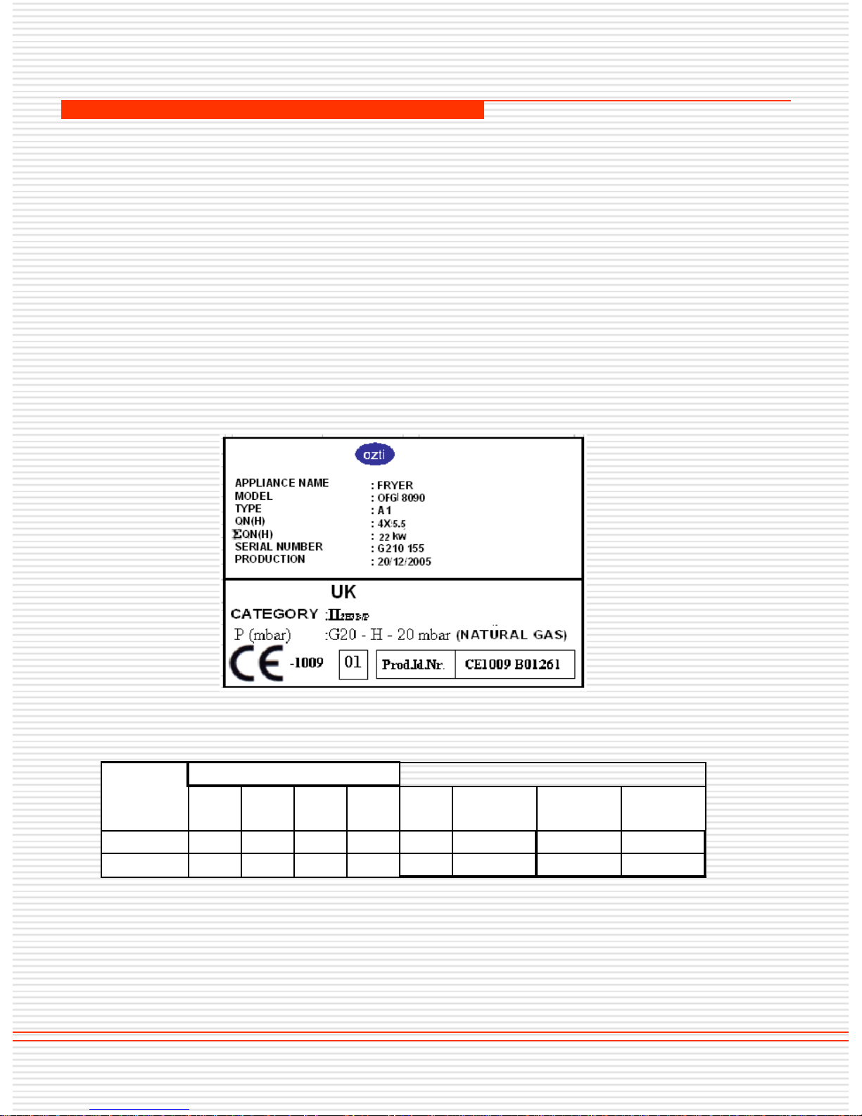
CHANGING THE GAS SYSTEM
CHANGING THE GAS SYSTEM
The appliances is designed for operating with the use of LPG or
network natural gas. The appliances should be operated according to the
system installed by the authorized service (LPG or natural gas). If the gas
system must be changed this should only be CARRIED OUT by authorized
service personnel. MANUFACTURER is not responsible for any problem
due to any gas systems changed by people except for authorized service
personnel. In this case ,the appliances will not be covered by the warranty.
On the label at gas inlet it is specified at which gas system the appliances
operates.
LIFE OF USE
Appliances life of use is 10 year if it is used under recommended
conditions.
15/16
SAMPLE LABEL
OFGI OFGI OFG OFG OFGI OFGI OFG OFG
4090 8090 4070 8070 4090 8090 4070 8070
22 kw 44 kw 10 kw 20 kw
2,32 m³/h
4,64 m³/h 1,06 m³/h 2,12 m³/h
22 kw 44 kw 10 kw 20 kw
1,72 kg/h
3,44 kg/h 0,78 kg/h 1,56 kg/h
GAS CONSUMPTION
POWER
GAS SYSTEM
USED
G20-NATURAL GAS
G30-LPG
Page 16
TERMS OF WARRANTY
1- Documents without sales date, factory and sales company approval
on, are not valid. In order to benefit from the warranty, warranty
document should be presented.
2- If the appliance is installed and operated following the instructions in
the installation, maintenance and user's manual, it is warranted for
failures sourcing from materials and workmanship .
3- The failures within the scope of warranty, how and where these will
be eliminated, and the way and place of maintenance is determined by
................
4- The warranty is only valid provided that the warranty terms and the
instructions in the installation, maintenance and user's manual are fully
complied with. The warranty is only valid for the warranted appliance,
and no other right or compensation for some other thing may be
claimed.
5- If the information about the kind and the type of the appliance, serial
numbers printed on the warranty document are scraped, rubbed or
changed, then the warranty is not valid.
6- The warranty covers only maintenance and repairing of material or
workmanship failure within the valid warranty period. Failures and
parts within the scope of the warranty are repaired and replaced
without any charge. Replaced parts belong to ................
7- The failures occurring in the appliance may only be handled by
service personnel authorized by ................ If people who are not
authorized handle the appliance, it will not be covered by the warranty.
8- Installation should be carried out by authorized service personnel
and the service should be informed about the location change of the
appliance.
9- When any failure occurs during operation, authorized service dealer
should be contacted.
10- Warranty does not cover failures and damages resulting from
loading, unloading and shipping, which are outside the responsibility
of ................ Similarly, failures and damages resulting from external
factors are not covered.
16/16
 Loading...