

Page 1

1
N6 1U Series DVR Quick Start Guide
Version 4.0
Page 2

2
Table of Contents
1 Hardware Installation and Connection..........................................................................5
1.1 Check Unpacked DVR ..........................................................................................5
1.2 About Front Panel and Rear Panel.....................................................................5
1.3 After Remove the Chassis....................................................................................5
1.4 HDD Installation .....................................................................................................5
1.5 Front Panel .............................................................................................................6
1.6 Rear Panel ..............................................................................................................8
1.7 Connection Sample ...............................................................................................9
1.8 Alarm Input and Output Connection ...................................................................9
1.8.1 Alarm Input and Output Details.................................................................9
1.8.2 Alarm Input Port.........................................................................................10
1.8.3 Alarm Output Port......................................................................................11
2 Overview of Navigation and Controls..........................................................................12
2.1 Login, Logout & Main Menu ...............................................................................12
2.1.1 Login............................................................................................................12
2.1.2 Main Menu..................................................................................................13
2.1.3 Logout .........................................................................................................13
2.1.4 Auto Resume after Power Failure ..........................................................14
2.2 Live Viewing..........................................................................................................14
2.3 Schedule ...............................................................................................................14
2.4 Manual Record.....................................................................................................15
2.5 Encode ..................................................................................................................15
2.5.1 Snapshot.....................................................................................................16
2.5.2 Image FTP..................................................................................................18
2.5.3 Snapshot Disk (For special series only) ................................................18
2.6 Search and Playback ..........................................................................................19
2.7 Network Setup......................................................................................................22
Page 3

3
2.8 Pan/Tilt/Zoom .......................................................................................................23
2.8.1 PTZ Setup ..................................................................................................23
2.8.2 PTZ Operation ...........................................................................................24
2.8.3 3D Intelligent Positioning Key .................................................................25
3 Web Client Operation ....................................................................................................26
3.1 Network Connection ............................................................................................26
3.2 Login ......................................................................................................................26
3.3 Main Window ........................................................................................................26
Appendix Toxic or Hazardous Materials or Elements .....................................................28
Page 4

4
Welcome
Thank you for purchasing our DVR!
This quick start guide will help you become familiar with our DVR in a very short time.
Here you can find hardware installation,cable connection information and general operations
such as system setup, record, search, backup, alarm setup, PTZ operation, also here you can
find web operation instruction.
Before installation and operation, please read the following safeguard and warning carefully!
Important Safeguard and Warning
1.Electrical safety
All installation and operation here should conform to your local electrical safety codes.
We assume no liability or responsibility for all the fires or electrical shock caused by improper
handling or installation.
2.Transportation security
Heavy stress, violent vibration or water splash are not allowed during transportation, storage and
installation.
3.Installation
Keep upwards. Handle with care.
Do not apply power to the DVR before completing installation.
Do not place objects on the DVR.
4.Qualified engineers needed
All the examination and repair work should be done by the qualified service engineers.
We are not liable for any problems caused by unauthorized modifications or attempted repair.
5.Environment
The DVR should be installed in a cool, dry place away from direct sunlight, inflammable,
explosive substances and etc.
6. Accessories
Be sure to use all the accessories recommended by manufacturer.
Before installation, please open the package and check all the components are included:
Contact your local retailer ASAP if something is missing in your package.
7. Lithium battery
Improper battery use may result in fire, explosion, or personal injury!
When replace the battery, please make sure you are using the same model!
Page 5
5
1 Hardware Installation and Connection
Note: All the installation and operations here should conform to your local
electric safety rules.
1.1 Check Unpacked DVR
When you receive the DVR from the forwarding agent, please check whether there is any visible
damage. The protective materials used for the package of the DVR can protect most accidental
clashes during transportation. Then you can open the box to check the accessories.
Please check the items in accordance with the list on the warranty card (Remote control is
optional). Finally you can remove the protective film of the DVR.
Note
Remote control is not a standard accessory and it is not included in the accessory bag.
1.2 About Front Panel and Rear Panel
For detailed information of the function keys in the front panel and the ports in the rear panel,
please refer to the User’s Manual included in the resource CD.
The model label in the front panel is very important; please check according to your purchase
order.
The label in the rear panel is very important too. Usually we need you to represent the serial
number when we provide the service after sales.
1.3 After Remove the Chassis
Please check the data cable, power cable, COM cable and main boar cable connection is secure
or not.
1.4 HDD Installation
You can refer to the User’s Manual for recommended HDD brand.
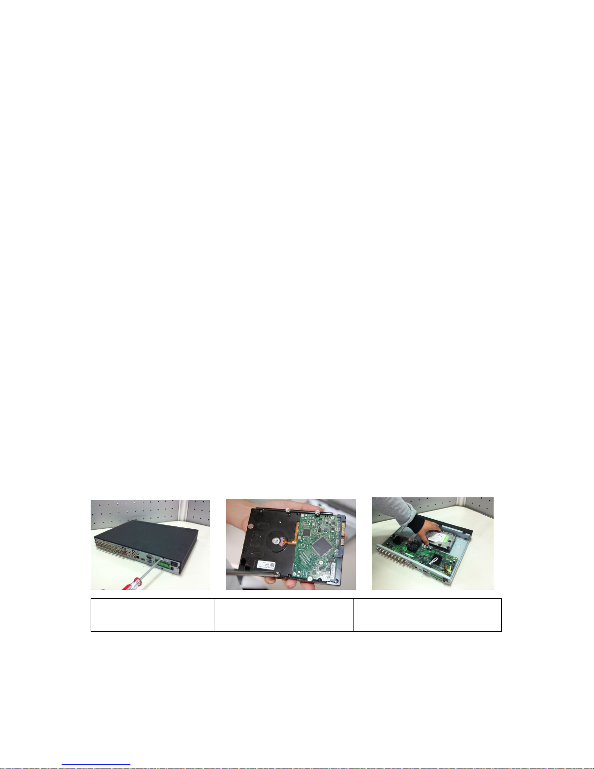
Please follow the instructions below to install hard disk.
This series DVR has two SATA HDDs. Please use HDD of 7200rpm or higher.
1. Loosen the screws of the
u
pp
er cover and side panel.
2. Fix four screws in the HDD
(
Turn just three rounds).
3. Place the HDD in accordance with
the four holes in the bottom.
Page 6
6
Important
When there is a bracket, please make sure the installation direction of HDDs is the same.
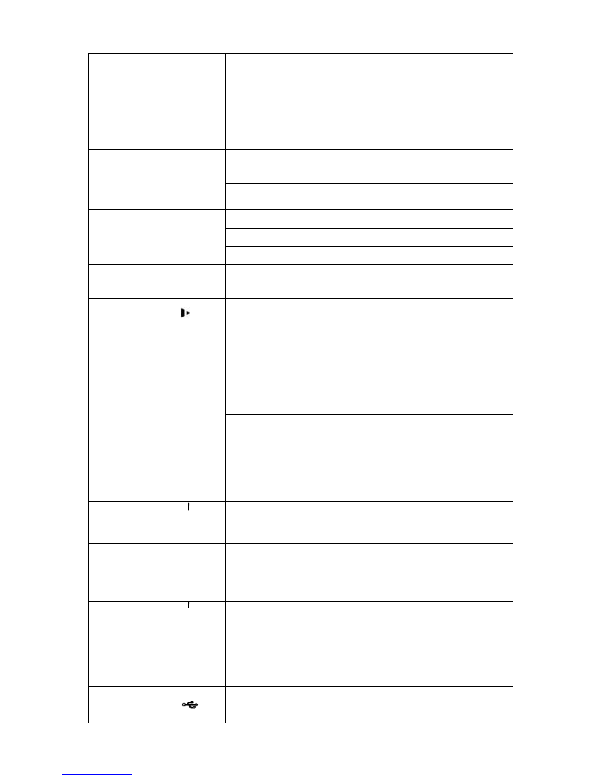
1.5 Front Panel
The front panel is shown as in Figure 1-1.
Figure 1-1
Please refer to the following sheet for front panel button information.
Name Icon Function
Power button
Power button, press this button for three seconds to boot up
or shut down DVR.
Shift Shift
In textbox, click this button to switch between numeral,
English(Small/Capitalized),donation and etc.
Activate current control, modify setup, and then move up
and down.
Up/1
Down/4
S、T
Increase/decrease numeral.
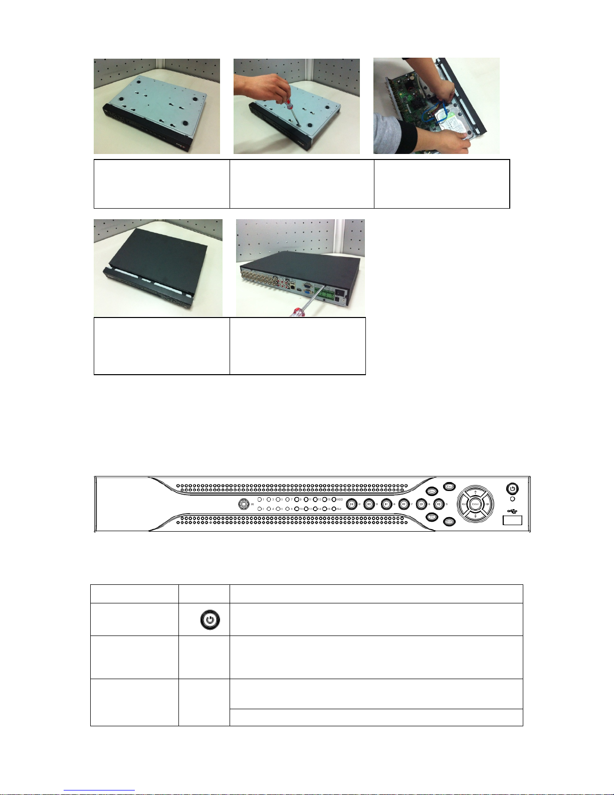
4. Turn the device upside down
and then turn the screws in
firml
y
.
5. Fix the HDD firmly.
6. Connect the HDD cable and
power cable.
7. Put the cover in accordance
with the clip and then place the
upper cover back.
8. Secure the screws in the
rear panel and the side panel.
Page 7
7
Assistant function such as PTZ menu.
In text mode, input number 1/4 (English character G/H/I)
Shift current activated control,
Left/2
Right/3
W X
When playback, click these buttons to control playback bar.
In text mode, input number 2(English character A/B/C)
/3(English character D/E/F)
Go to previous menu, or cancel current operation.
ESC ESC
When playback, click it to restore real-time monitor mode.
Confirm current operation
Go to default button
Enter ENTER
Go to menu
Record REC
Manually stop/start recording, working with direction keys
or numeral keys to select the recording channel.
Slow play/8
Multiple slow play speeds or normal playback.
In text mode, input number 8 (English character T/U/V).
One-window monitor mode, click this button to display
assistant function: PTZ control and image color.
Backspace function: in numeral control or text control, press
it for 1.5seconds to delete the previous character before the
cursor.
In motion detection setup, working with Fn and direction
keys to realize setup.
In text mode, click it to switch between numeral, English
character(small/capitalized) and etc.
Assistant Fn
Realize other special functions.
Fast play/7
Various fast speeds and normal playback.
In text mode, input number 7 (English character P/Q/R/S).
Play
previous/0
_
In playback mode, playback the previous video
In text mode, input number 0.
Reverse/Pau
se/6
W
In normal playback or pause mode, click this button to
reverse
playback
In reverse playback, click this button to pause playback.
In text mode, input number 6 (English character M/N/O)
Play Next/9
f
In playback mode, playback the next video
In menu setup, go to down ward of the dropdown list.
In text mode, input number 9 (English character W/X/Y/Z)
Play/Pause /5
f
In normal playback click this button to pause playback
In pause mode, click this button to resume playback.
In text mode, input number 5(English character J/K/L).
USB port
To connect USB storage device, USB mouse.
Page 8
8
Network
abnormal
indication
light
Net
Network error occurs or there is no network connection, the
light becomes red to alert you.
HDD
abnormal
indication
light
HDD
HDD error occurs or HDD capacity is below specified
threshold value, the light becomes red to alert you.
Record light 1-16
System is recording or not. It becomes on when system is
recording.
IR Receiver IR
It is to receive the signal from the remote control.
Alarm
indication
light
Alarm
Here you can view there is external alarm input or not. The
light becomes on when there is an external alarm. The light
become off when the external alarm stops.
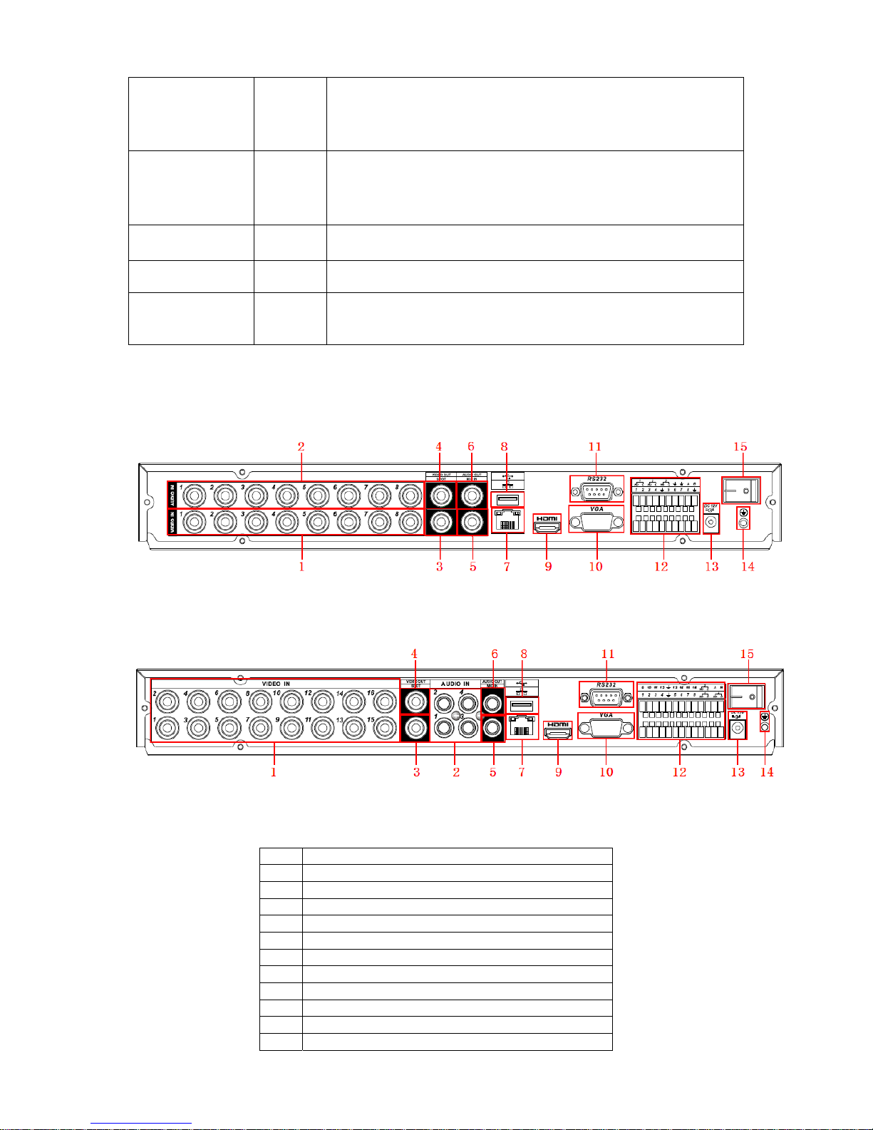
1.6 Rear Panel
The 4/8-channel series DVR rear panel is shown as below. See Figure 1-2.
Figure 1-2
The 16-channel series DVR rear panel is shown as below. See Figure 1-3.
Figure 1-3
Please refer to the following sheet for detailed information.
1 Video input
2 Audio input
3 Video spot output
4 Video CVBS output
5 Bidirectional talk input
6 Audio output
7 Network port
8 USB port
9 HDMI port
10 Video VGA output
11 RS232 port
12 Alarm input/alarm output/RS485 port
Page 9
9
13 Power socket
14 GND port
15 On/off button
When connect the Ethernet port, please use crossover cable to connect the PC and use the
straight cable to connect to the switcher or router.
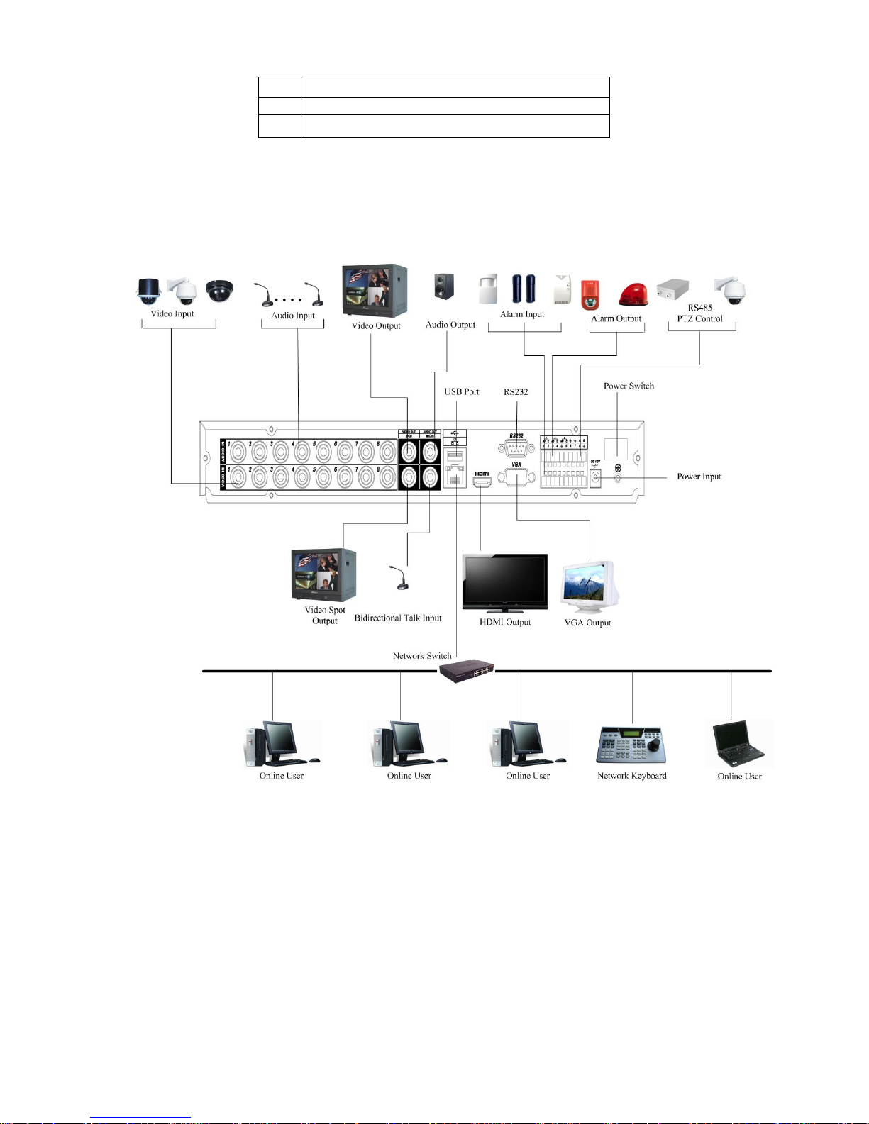
1.7 Connection Sample
Please refer to Figure 1-4 for connection sample.
The following figure is based on the 8-channel series product.
Figure 1-4
1.8 Alarm Input and Output Connection
Important
Please refer to the specifications for the alarm input and output channel amount. Do not
merely count the alarm input and out channel amount according to the ports on the rear
panel.
There are two alarm input types for you to select: normal open (NO) and normal close (NC).
1.8.1 Alarm Input and Output Details
Page 10
10
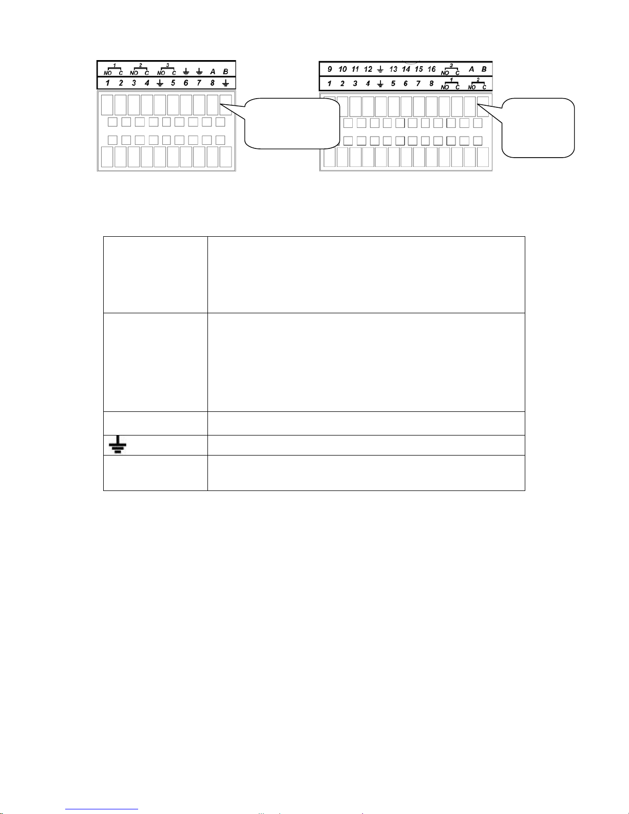
4/8-channel series 16-channel series
Figure 1-5
You can refer to the following sheet and Figure 1-5 for alarm input and output information.
In the first line, from
the left to the right,:
1 , 2 ,3 , 4 , 5 ,
6,7, 8, 9 , 10 ,
11, 12 , 13 , 14,
15,16
ALARM 1 to ALARM 16. The alarm becomes active in low voltage.
In the second line,
from the left to the
right:
NO1 C1,
NO2 C2,
NO3 C3,
NO4 C4,
NO5 C5 NC5
The first four are four groups of normal open activation output
(on/off button)
NO5 C5 NC5 is a group of NO/NC activation output (on/off button)
CTRL 12V Control power output. You need to close the device power to cancel
the alarm.
Earth cable.
485 A/B 485 communication port. They are used to control devices such as
PTZ. Please parallel connect 120TΩ between A/B cables if there are
too many PTZ decoders.
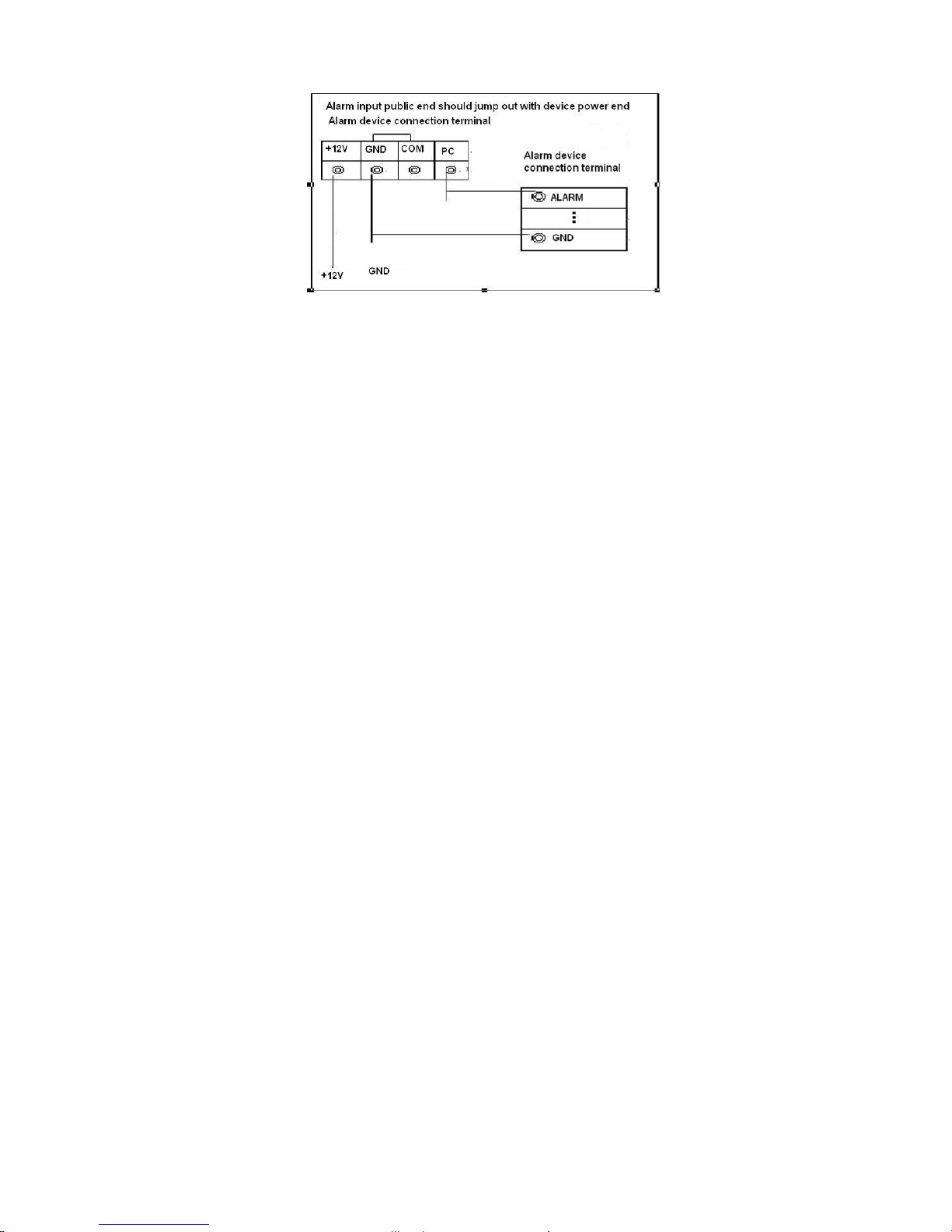
1.8.2 Alarm Input Port
Please refer to the following sheet for more information.
z Normal open or Normal close type.
z Please parallel connect COM end and GND end of the alarm detector (Provide external
power to the alarm detector).
z Please parallel connect the Ground of the DVR and the ground of the alarm detector.
z Please connect the NC port of the alarm sensor to the DVR alarm input(ALARM)
z Use the same ground with that of DVR if you use external power to the alarm device.
AB cable
connection
AB cable
connection
Page 11
11
Figure 1-6
1.8.3 Alarm Output Port
z Provide external power to external alarm device.
z To avoid overloading, please read relay parameters sheet in the Use r’s Manual carefully.
z RS485 A/B cable is for the A/B cable of the PTZ decoder.
Page 12
12
2 Overview of Navigation and Controls
Before operation, please make sure:
z You have properly installed HDD and all the cable connections.
z The provided input power and the device power are matched.
z The external power shall be DC 12 V.
z Always use the stable current, if necessary UPS is a best alternative measure.
2.1 Login, Logout & Main Menu
2.1.1 Login
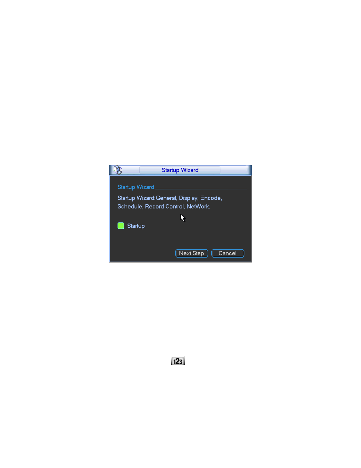
After system booted up, system pops up the startup wizard.
Click the Cancel button; you can go to the system login interface.
Click the Next Step button; you can go to the startup wizard interface. Here you can set the
system basic information. See Figure 2-1.
Figure 2-1
The system login interface is shown as in Figure 2-2.
System consists of four accounts:
z Username: admin. Password: admin. (administrator, local and network)
z Username: 888888. Password: 888888. (administrator, local only)
z Username: 666666. Passwords: 666666(Lower authority user who can only monitor, playback,
backup and etc.)
z Username: default. Password: default(hidden user)
You can use USB mouse, front panel, remote control (not included in the accessory bag) or
keyboard to input. About input method: Click
to switch between numeral, English character
(small/capitalized) and denotation.
Note:
For security reason, please modify password after you first login.
Within 30 minutes, three times login failure will result in system alarm and five times login failure
will result in account lock!
Page 13
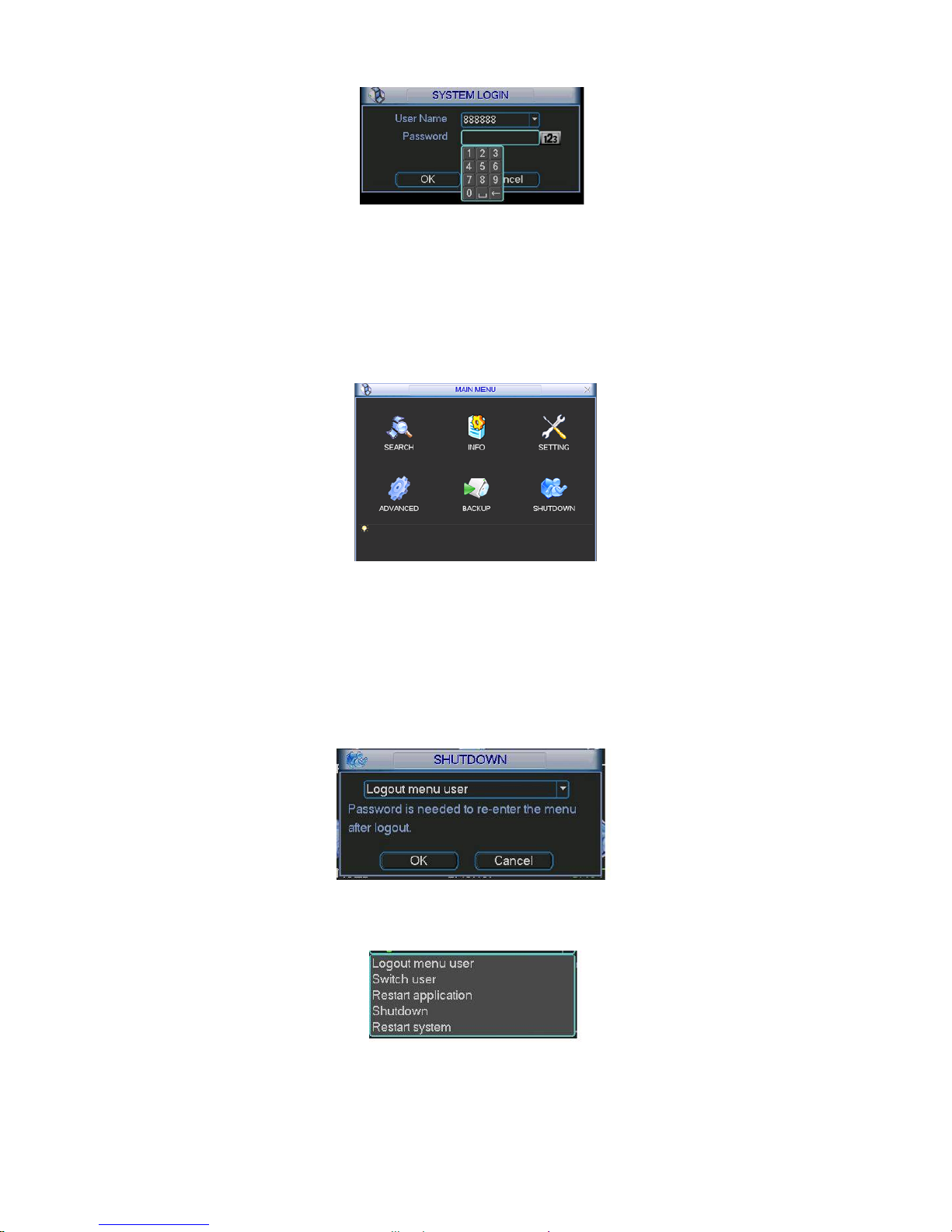
13
Figure 2-2
2.1.2 Main Menu
After you logged in, the system main menu is shown as below. See Figure 2-3.
There are total six icons: search, information, setting, backup, advanced and shutdown.
You can move the cursor to highlight the icon, and then double click mouse to enter the sub-
menu.
Figure 2-3
2.1.3 Logout
There are two ways for you to log out.
The first one is from menu option:
In the main menu, click shutdown button, you can see an interface is shown as below. See
Figure 2-4.
Figure 2-4
There are several options for you. See Figure 2-5.
Figure 2-5
The other ways is to press power button on the front panel for at least 3 seconds, system will
stop all operations. Then you can click the power button in the front panel to turn off the DVR.
Page 14
14
Please note, before you replace the HDD, do remember shutting down the device and unplug the
power cable.
2.1.4 Auto Resume after Power Failure
The system can automatically backup video and resume previous working status after power
failure.
2.2 Live Viewing
After you logged in, the system is in live viewing mode by default. You can see system date, time
and channel name. If you want to change system date and time, you can refer to general settings
(Main Menu->Setting->General). If you want to modify the channel name, please refer to the
display settings (Main Menu->Setting->Display)
2.3 Schedule
Note:
You need to have proper rights to implement the following operations. Please make sure the
HDDs have been properly installed.
After the system booted up, it is in default 24-hour regular mode. You can set record type and
time in schedule interface.
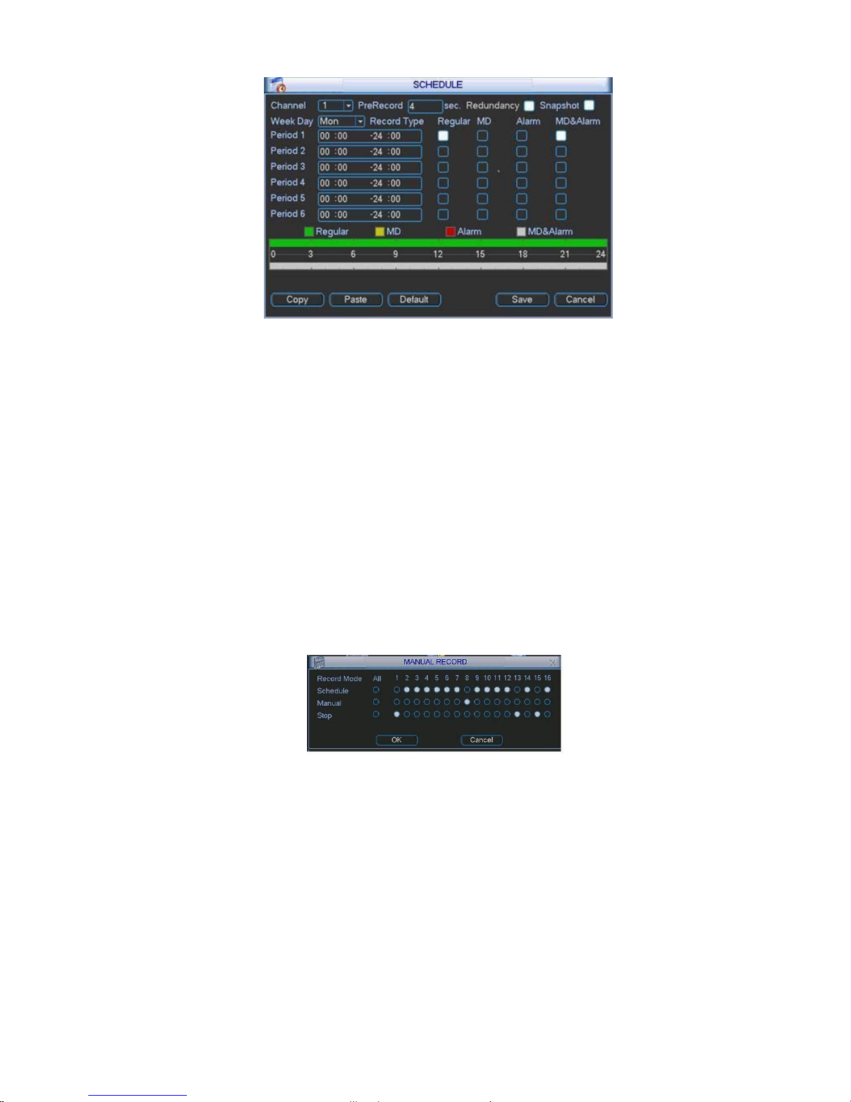
In the main menu, from Setting to Schedule, you can go to schedule menu. See Figure 2-6.
There are total six periods.
z Channel: Please select the channel number first. You can select “all” if you want to set for
the whole channels.
z Week day: There are eight options: ranges from Saturday to Sunday and all.
z Pre-record: System can pre-record the video before the event occurs into the file. The value
ranges from 1 to 30 seconds depending on the bit stream.
z Redundancy: System supports redundancy backup function. You can highlight Redundancy
button to activate this function. Please note, before enable this function, please set at least
one HDD as redundant. (Main menu->Advanced->HDD Management).
z Snapshoot: You can enable this function to snapshoot image when alarm occurs.
z Record types: There are four types: regular, motion detection (MD), Alarm, MD & alarm.
Please highlight icon
to select the corresponding function. After completing all the setups
please click save button, system goes back to the previous menu.
At the bottom of the menu, there are color bars for your reference. Green color stands for
regular recording, yellow color stands for motion detection and red color stands for alarm
recording. The white means the MD and alarm record is valid. Once you have set to record
when the MD and alarm occurs, system will not record neither motion detect occurs nor the
alarm occurs.
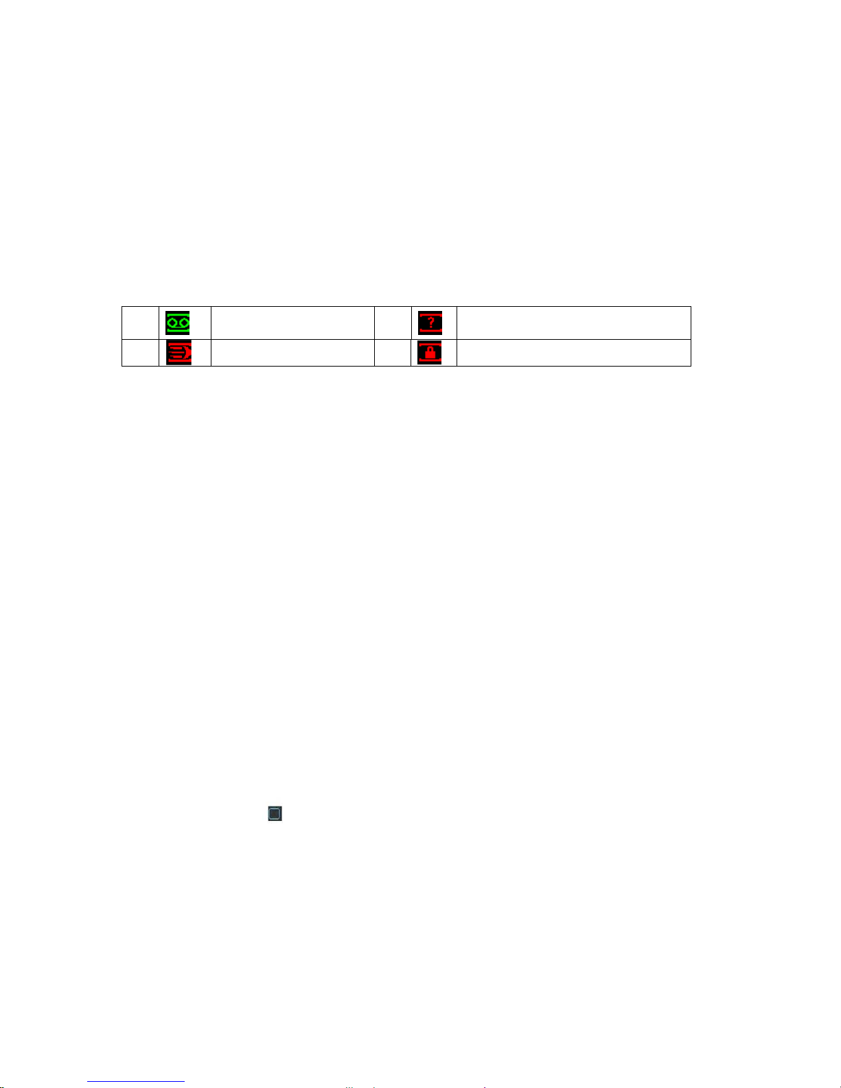
1
Recording status
3
Video loss
2
Motion detection
4
Camera lock
Page 15
15
Figure 2-6
2.4 Manual Record
Note:
Please make sure you have the record operation right and you have properly installed the
formatted HDD.
You can right click mouse or in the main menu, from Advanced->Manual Record to go to record
interface.
There are three statuses: schedule/manual/stop. Highlight icon“○” to select corresponding
channel. See Figure 2-7.
z Manual: The highest priority. After manual setup, all selected channels will begin ordinary
recording.
z Schedule: Channel records as you have set in recording setup (Main Menu->Setting-
>Schedule)
z Stop: All channels stop recording.
Figure 2-7
2.5 Encode
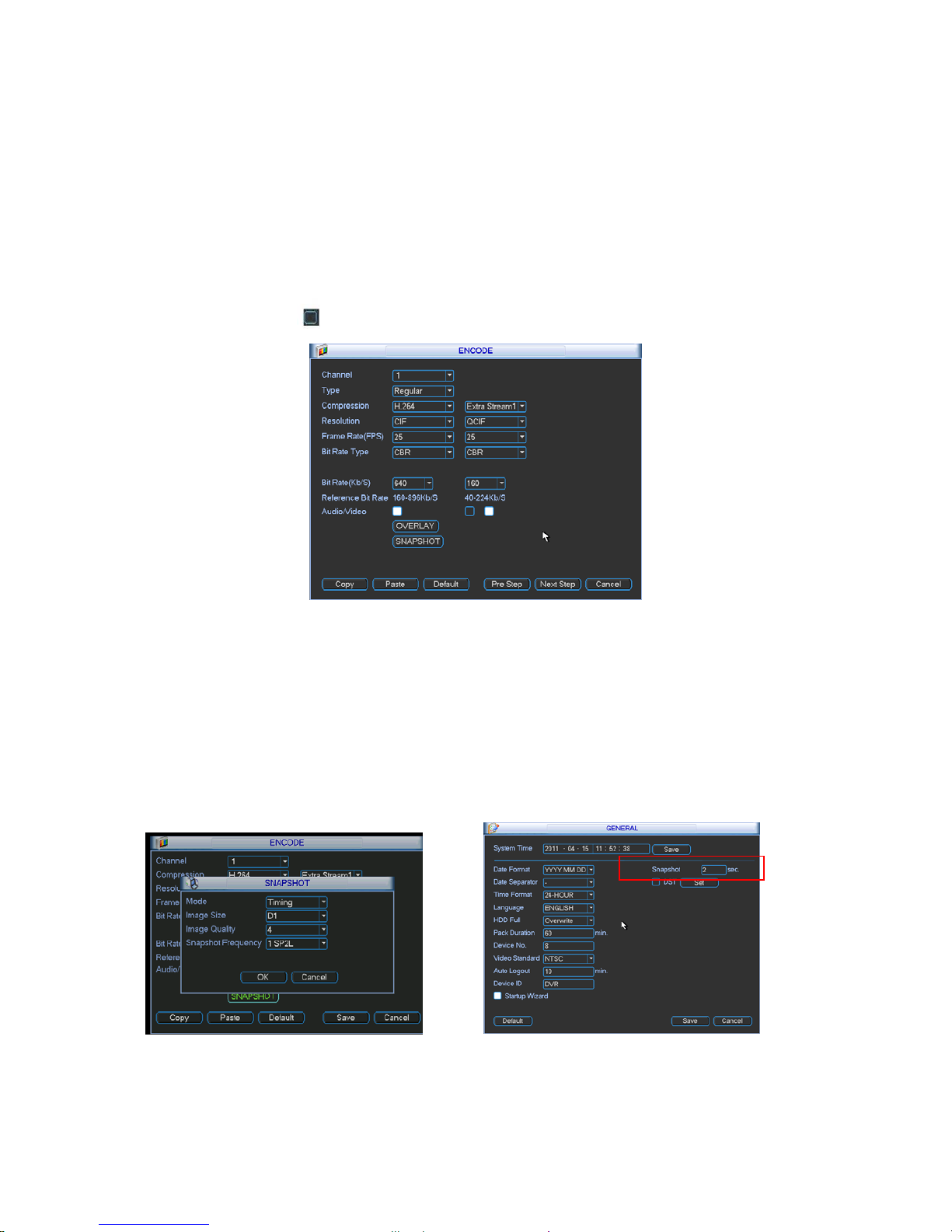
Encode interface is shown as in Figure 2-8.
z Channel: Select the channel you want.
z Type: Please select from the dropdown list. There are three options: regular/motion
detect/alarm. You can set the various encode parameters for different record types.
z Compression: System supports H.264.
z Resolution: System supports various resolutions, you can select from the dropdown list. The
main stream supports D1/HD1/2CIF/CIF/QCIF.The extra stream supports CIF/QCIF. Please
note the frame rate may vary due to different channels.
Page 16
16
z Frame rate: It ranges from 1f/s to 25f/s in NTSC mode and 1f/s to 30f/s in PAL mode.
z Bit rate type: system supports two types: CBR and VBR. In VBR mode, you can set video
quality.
z Quality: There are six levels ranging from 1 to 6. The sixth level has the highest image
quality.
z Video/audio: you can enable or disable the video/audio. Please note the video is enabled for
main stream by default. For extra stream, please enable video first and then enable audio.
z Snapshot: Click snapshot button, you can see it contains the four items: mode/image
size/image quality/snapshot frequency. Please refer to chapter 2.3.3 for detail information.
Please highlight icon
to select the corresponding function.
Figure 2-8
2.5.1 Snapshot
2.5.1.1 Schedule Snapshot
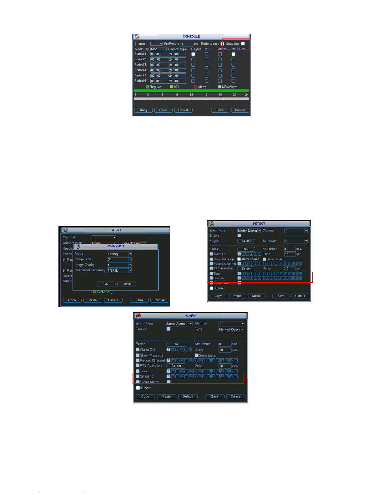
In Encode interface, click snapshot button to input snapshot mode, size, quality and
frequency.
In General interface please input upload interval.
In Schedule interface, please enable snapshot function.
Please refer to the following figure for detailed information. See Figure 2-9.
Page 17
17
Figure 2-9
2.5.1.2 Activation Snapshot
Please follow the steps listed below to enable the activation snapshot function. After you
enabled this function, system can snapshot when the corresponding alarm occurred.
z In Encode interface, click snapshot button to input snapshot mode, size, quality and
frequency.
z In General interface please input upload interval.
z In Detect interface please enable snapshot function for specified channels. Or in Alarm
interface please enable snapshot function for specified channels.
Please refer to the following figure for detailed information. See Figure 2-10.
Figure 2-10
2.5.1.3 Priority
Page 18
18
Please note the activation snapshot has the higher priority than schedule snapshot. If you
have enabled these two types at the same time, system can activate the activation snapshot
when alarm occurs, and otherwise system just operates the schedule snapshot.
2.5.2 Image FTP
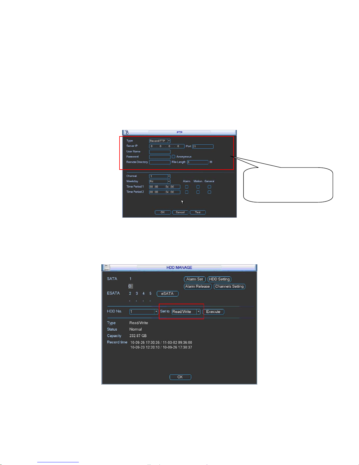
In Network interface, you can set FTP server information. Please enable FTP function and
then click save button. See Figure 2-11.Please refer to the User’s Manual included in the
resource CD for detailed information.
Please boot up corresponding FTP server.
Please enable schedule snapshot or activation snapshot (Chapter 2.5.1) and then system
can upload the image file to the FTP server.
Figure 2-11
2.5.3 Snapshot Disk (For special series only)
Set one disk as snapshot (Main menu->Advanced->HDD management) and then click execute
button. See Figure 2-12. System needs to reboot to get current setup activated.
Figure 2-12
All scheduled snapshot files or activated snapshot files will be memorized in the snapshot
disk.
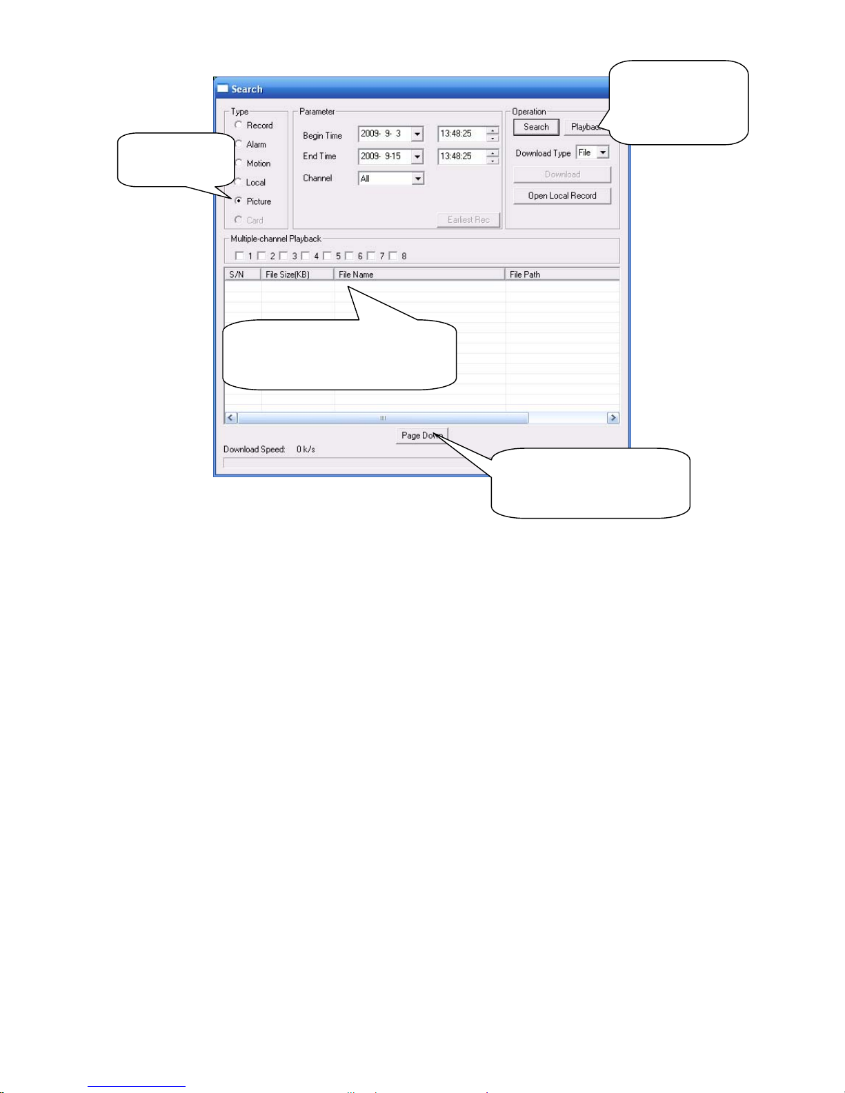
You can search the corresponding images via Web. See Figure 2-13.
Please input the corresponding
information here, if you just
upload the image FTP.
Page 19
19
Figure 2-13
2.6 Search and Playback
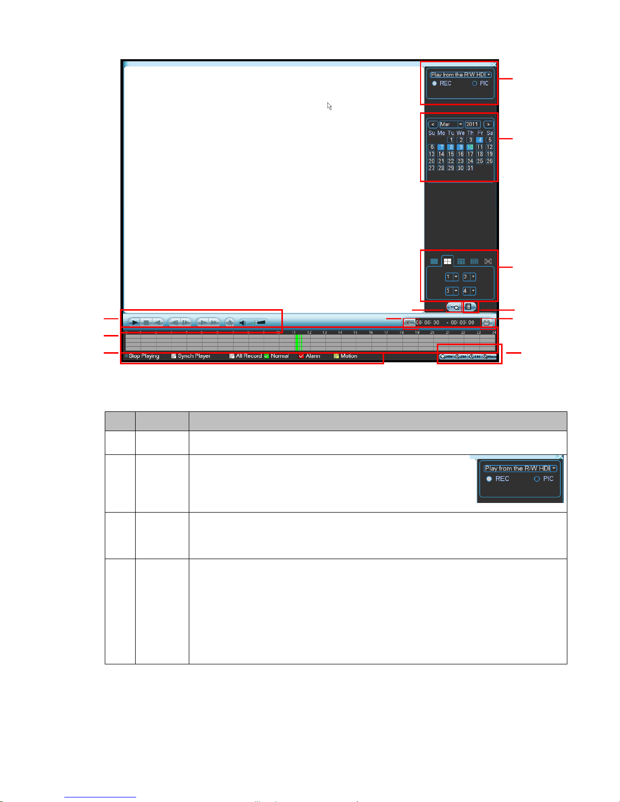
Click search button in the main menu, search interface is shown as below. See Figure 2-14.
Usually there are three file types:
z R: Regular recording file.
z A: External alarm recording file.
z M: Motion detection recording file.
Select search
engine here
You can see result here. Double click
file name, you can view the image
content.
There are max 100 files in one
page. Click here to view more.
Select a file and then
click here to view
image content.
Page 20
20
Figure 2-14
Please refer to the following sheet for more information.
SN Name Function
1
Display
window
zHere is to display the searched picture or file.
zSupport 1/4/9/16-window playback.
2
Search
type
zHere you can select to search the picture or the recorded
file.
zWhen there is displayed picture on the left pane, you can
set the corresponding setup
3 Calendar
zThe blue highlighted date means there is picture or file. Otherwise, there is no
picture or file.
zIn any play mode, click the date you want to see, you can see the corresponding
record file trace in the time bar.
4
Playback
mode
and
channel
selection
pane.
zPlayback mode:1/4/9/16. (It may vary due to different series.)
In 1-window playback mode: you can select 1-16 channels.
In 4-window playback mode: you can select 4 channels according to your
requirement.
In 9-window playback mode, you can switch between 1-9 and 10-16 channels.
In 16-window playback mode, you can switch between1-16 and 17-32
channels.
zThe time bar will change once you modify the playback mode or the channel
option.
1
2
3
4
56
7
8
12 9
10
11
Page 21
21
5
File list
switch
button
zDouble click it, you can view the picture/record file list of current day.
zThe file list is to display the first channel of the record file.
zThe system can display max 128 files in one time. Use the S/T or the mouse to
view the file. Select one item, and then double click the mouse or click the ENTER
button to playback.
zYou can input the period in the following interface to begin accurate search.
zFile type:R—regular record; A—external alarm record;M—Motion detect
record.
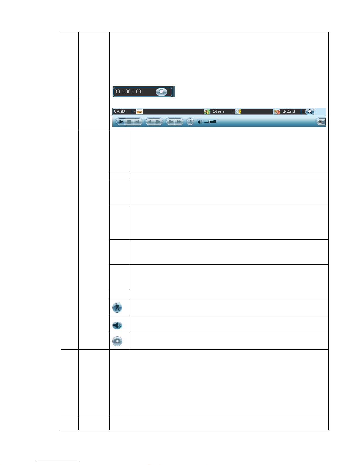
6
Card
number
search
The card number search interface is shown as below.
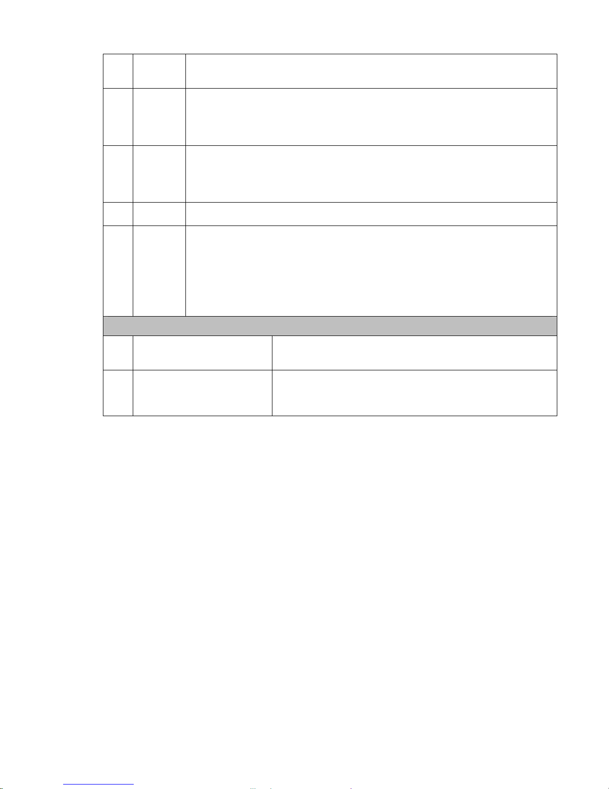
►/
Play/Pause
There are three ways for you to begin playback.
z The play button
z Double click the valid period of the time bar.
z Double click the item in the file list.
In slow play mode, click it to switch between play/pause.
■ Stop
W
Backward play
In normal play mode, left click the button, the file begins backward play.
Click it again to pause current play.
In backward play mode, click ►/ to restore normal play.
│W/
X│
In playback mode, click it to play the next or the previous section. You can
click continuously when you are watching the files from the same channel.
In normal play mode, when you pause current play, you can click W│ and
│X to begin frame by frame playback.
In frame by frame playback mode, click ►/ to restore normal playback.
►
Slow play
In playback mode, click it to realize various slow play modes such as slow
play 1, slow play 2, and etc.
Fast forward
In playback mode, click to realize various fast play modes such as fast
play 1,fast play 2 and etc.
Note: The actual play speed has relationship with the software version.
Smart search
The volume of the playback
7
Playback
control
pane.
Click the snapshot button in the full-screen mode, the system can snapshot
1 picture per second.
8 Time bar
zIt is to display the record type and its period in current search criteria.
zIn 4-window playback mode, there are corresponding four time bars. In other
playback mode, there is only one time bar.
zUse the mouse to click one point of the color zone in the time bar, system begins
playback.
zThe time bar is beginning with 0 o'clock when you are setting the configuration.
The time bar zooms in the period of the current playback time when you are
playing the file.
zThe green color stands for the regular record file. The red color stands for the
external alarm record file. The yellow stands for the motion detect record file.
9
Time bar
unit
●The option includes: 24H, 12H, 1H and 30M. The smaller the unit, the larger the
zoom rate. You can accurately set the time in the time bar to playback the record.
Page 22
22
zThe time bar is beginning with 0 o'clock when you are setting the configuration.
The time bar zooms in the period of the current playback time when you are
playing the file.
10 Backup
Select the file(s) you want to backup from the file list. System max supports files
from four channels. Then click the backup button, now you can see the backup
menu. Click the start button to begin the backup operation.
Check the file again you can cancel current selection.
System max supports to display 32 files from one channel.
11 Clip
zIt is to edit the file.
●Please play the file you want to edit and then click this button when you want to
edit. You can see the corresponding slide bar in the time bar of the corresponding
channel. You can adjust the slide bar or input the accurate time to set the file end
time. Click this button again and then save current contents in a new file. .
12
Record
type
In any play mode, the time bar will change once you modify the search type.
13
Smart
search
z When system is playing, you can select a zone in the window to begin motion
detect. Click the motion detect button to begin play.
z Current button is null once the motion detect play has begun.
z The system will take the whole play zone as the motion detect region by
default.
z The motion detect play stopped once you switch the play file.
z Operations such as set time bar, click the play button, or any file list operation
will stop current motion detect play.
Other Functions
14
Other channel
synchronization switch to
play when playback
When playing the file, click the number button, system can
switch to the same period of the corresponding channel to
play.
15 Digital zoom
When the system is in full-screen playback mode, left click
the mouse in the screen. Drag your mouse in the screen to
select a section and then left click mouse to realize digital
zoom. You can right click mouse to exit.
Note:
All the operations here (such as playback speed, channel, time and progress) have
relationship with hardware version. Some series DVRs do not support some functions or
playback speeds.
2.7 Network Setup
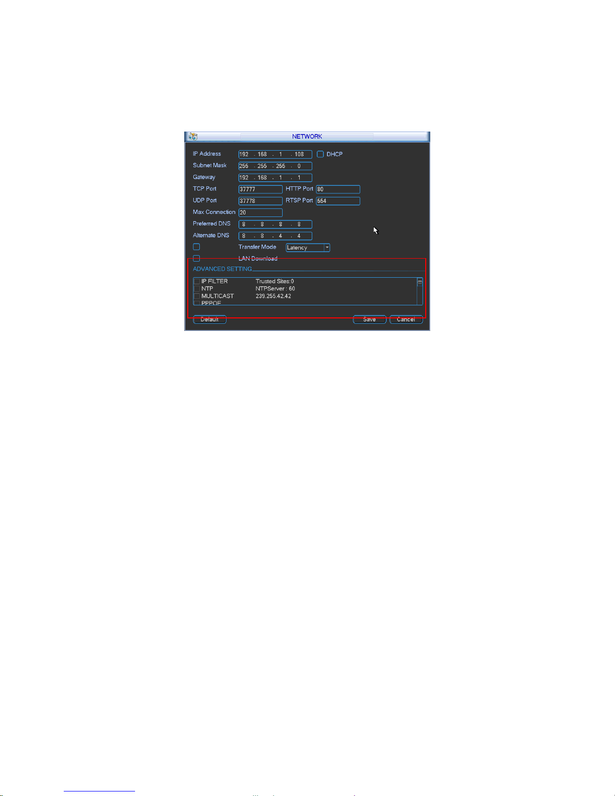
Here is for you to input network information. See Figure 2-15.
z IP address: Here you can input IP address.
z DHCP: It is auto search IP function. When enable DHCP function, you can not modify
IP/Subnet mask /Gateway. These values are from DHCP function. If you have not enabled
DHCP function, IP/Subnet mask/Gateway display as o. You need to disable DHCP function
to view current IP information. Besides, when PPPoE is operating, you can not modify
IP/Subnet mask /Gateway.
z TCP port: Default value is 37777.
z RTSP port: Default value is 554.
z UDP port: Default value is 37778.
z HTTP port: Default value is 80.
z Max connection: system support maximal 10 users. 0 means there is no connection limit.
z Preferred DNS server: DNS server IP address.
z Alternate DNS server: DNS server alternate address.
Page 23
23
z Transfer mode: Here you can select the priority between fluency/video qualities.
z Network download: System can process the downloaded data first if you enable this function.
z Advanced setting: Please refer to the user’s manual included in the resource CD for detailed
information.
After completing all the setups please click save button, system goes back to the previous menu.
Figure 2-15
2.8 Pan/Tilt/Zoom
Please note:
z Slight difference may be found in the user’s interface, due to various protocols.
z Please make sure the speed domes A/B cables are properly connected to the A/B ports of
DVR.
z You have properly set PTZ information.
z Please switch camera monitor channel to current window.
2.8.1 PTZ Setup
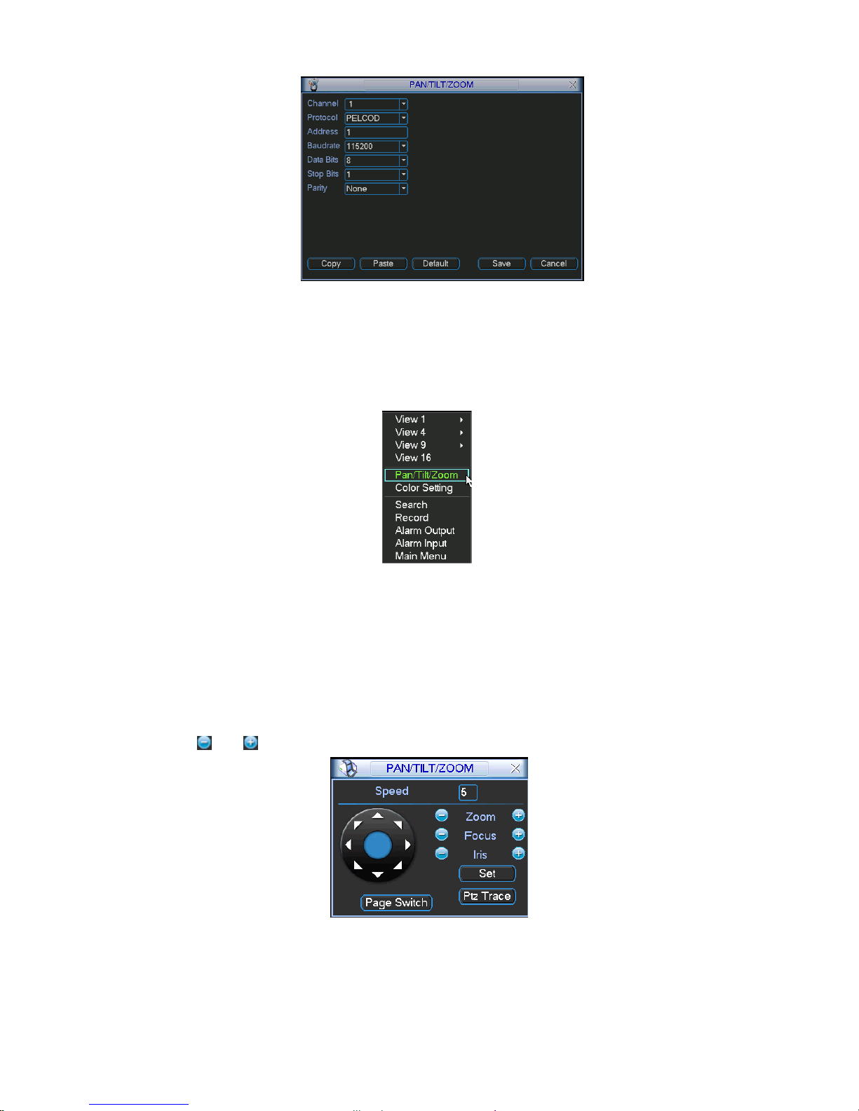
The pan/tilt/zoom setup includes the following items. Please select channel first. See Figure 2-16.
z Protocol: Select corresponding PTZ protocol such as PELCOD.
z Address: Input corresponding PTZ address.
z Baud rate: Select baud rate.
z Data bit: Select data bit. Default value is 8.
z Stop bit: Select stop bit. Default value is 1.
z Parity: There are three choices: none/odd/even. Default value is none.
Page 24
24
Figure 2-16
After completing all the setups please click save button, system goes back to the previous menu.
2.8.2 PTZ Operation
In one window display mode, right click mouse (click “Fn” Button in the front panel or click
“Fn” key in the remote control). The interface is shown as in Figure 2-17.
Figure 2-17
Click Pan/Tilt/Zoom, the interface is shown as below. See Figure 2-18.
Here you can set the following items:
z Step: value ranges from 1 to 8.
z Zoom
z Focus
z Iris
Click icon
and to adjust zoom, focus and iris.
Figure 2-18
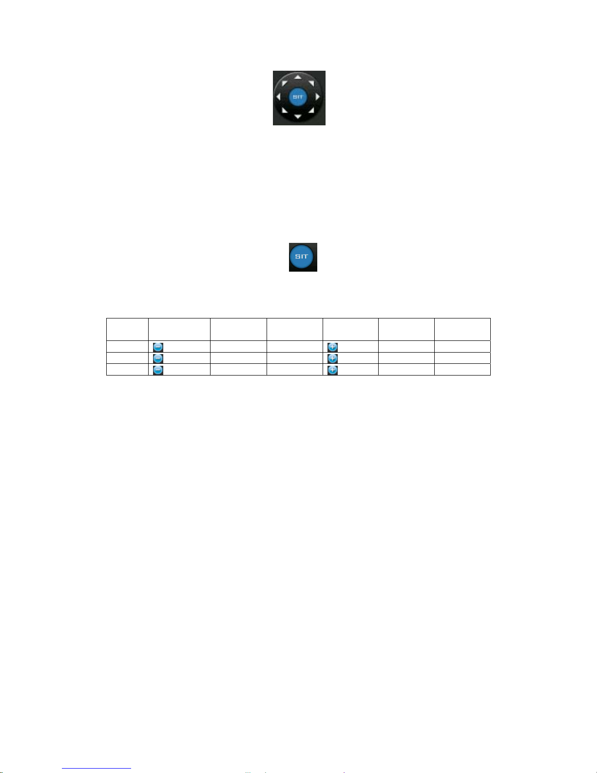
In Figure 2-18, please click direction arrows (See Figure 2-19) to adjust PTZ position. There are
total 8 direction arrows. Please note if you use remote control, you can use just four directions
(Up/down/left/right).
Page 25
25
The speed value ranges from 1 to 8.
Figure 2-19
2.8.3 3D Intelligent Positioning Key
In the middle of the eight direction arrows, there is a 3D intelligent positioning key. See Figure
2-20. Please note, this function needs protocol supported and can only be operated by mouse.
Click this key, system goes back to the single screen mode. Drag the mouse in the screen to
adjust section size. It can realize PTZ automatically.
Figure 2-20
Here is a sheet for you reference.
Name Function
key
function Shortcut
key
Function
key
function Shortcut
Key
Zoom
Near ►
Far
Focus
Near
_
Far ►
Iris
close
W
Open
f
You can click set button in Figure 2-18 (or click REC button in the front panel) to set preset, tour,
and pattern.
You can click page switch button in Figure 2-18 (or click Fn button in the front panel) to call main
function.
Page 26
26
3 Web Client Operation
Slightly difference may be found in the interface due to different series.
3.1 Network Connection
Before web client operation, please check the following items:
z Network connection is right
z DVR and PC network setup is right. Please refer to network setup(main menu->setting-
>network)
z Use order ping ***.***.***.***(* DVR IP address) to check connection is OK or not. Usually
the return TTL value should be less than 255.
z System can automatically download latest web control and the new version can overwrite
the previous one.
z If you want to un-install the web controls, please run uninstall webrec2.0.bat to auto delete
the control or you can go to C:\Program Files\webrec to delete Single folder.
3.2 Login
Open IE and input DVR address in the address column. For example, if your DVR IP is
10.10.3.16, then please input http:// 10.10.3.16 in IE address column.
System pops up warning information to ask you whether install webrec.cab control or not. Please
click yes button.
If you can’t download the ActiveX file, please modify your IE security setup.
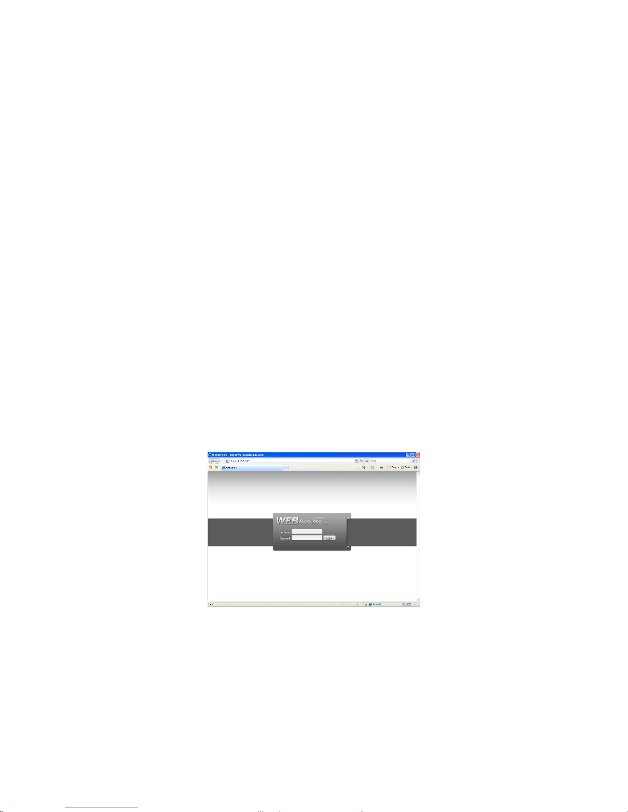
After installation, the interface is shown as below. See Figure 3-1.
Please input your user name and password.
Default factory name is admin and password is admin.
Note: For security reasons, please modify your password after you first login.
Figure 3-1
3.3 Main Window
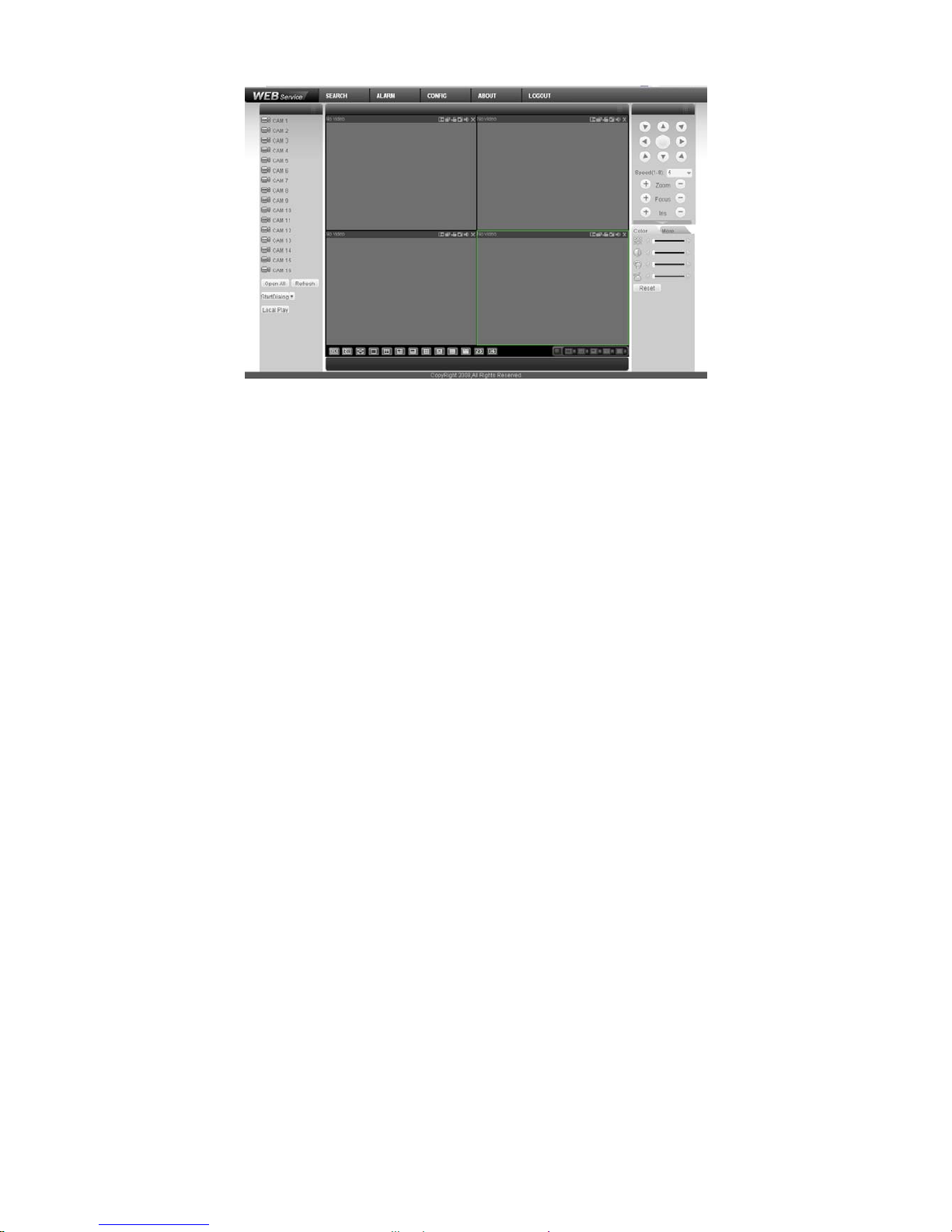
After you logged in, you can see the main window. See Figure 3-2.
Click the channel name on the left side; you can view the real-time video.
For detailed operation information, please refer to the User’s Manual included in the resources
CD.
Page 27
27
Figure 3-2
Page 28

28
Appendix Toxic or Hazardous Materials or Elements
Toxic or Hazardous Materials or Elements
Component
Name
Pb Hg Cd Cr VI PBB PBDE
Sheet
Metal(Case)
○ ○ ○ ○ ○ ○
Plastic Parts
(Panel)
○ ○ ○ ○ ○ ○
Circuit Board ○ ○ ○ ○ ○ ○
Fastener ○ ○ ○ ○ ○ ○
Wire and
Cable/AC
Adapter
○ ○ ○ ○ ○ ○
Packing
Material
○ ○ ○ ○ ○ ○
Accessories ○ ○ ○ ○ ○ ○
Note
O: Indicates that the concentration of the hazardous substance in all homogeneous materials in
the parts is below the relevant threshold of the SJ/T11363-2006 standard.
X: Indicates that the concentration of the hazardous substance of at least one of all
homogeneous materials in the parts is above the relevant threshold of the SJ/T11363-2006
standard. During the environmental-friendly use period (EFUP) period, the toxic or hazardous
substance or elements contained in products will not leak or mutate so that the use of these
(substances or elements) will not result in any severe environmental pollution, any bodily injury or
damage to any assets. The consumer is not authorized to process such kind of substances or
elements, please return to the corresponding local authorities to process according to your local
government statutes.
Note
z For detailed operation introduction, please refer to our resource CD included in your
package for electronic version of the User’s Manual.
z Slight difference may be found in user interface.
z All the designs and software here are subject to change without prior written notice.
z If there is any uncertainty or controversy, please refer to the final explanation of us.
z Please visit our website for more information.
 Loading...