

Ozroll OZS251E, OZS252E, OZS402E, OZS403E, OZS301E Installation Manual
...


SUPPLY BY THE MANUFACTURER
The following Standard items are supplier to the Installer with each Our Solar Hot Water System
1. Storage tank
2. Flat plate solar collector (s)
3. Roof mounting system for Standard pitched roof installations
4. Roof mounting brass fittings kit including temperature well and air valve
5. Flow restrictor to suit either 1 collector or 2 collector system
6. Booster heating element Either 2.4 kw (250,300 litre tank) or 3.6kw (400 litre tank)
7. Thermostat
8. Thermostat mounting bracket
9. System controller
10. Circulation Pump
11. Housing for system controller and pump assembly
12. Pressure / Temperature Relief ( P / T ) valve
13. Additional valves may be provided by the manufacturer – Specific to client
14. Polyslab base.
SUPPLY BY THE INSTALLER
The following items are to be supplied by the installer
1. All labour required to fully install, test and commission the system
2. Copper piping ( DN15 ) to complete the installation
3. Thermal UV resistant insulation for all copper piping 13mm
4. Brass fittings including joiners, copper olives, elbows etc to complete the installation
5. Any additional valves or fittings required under local regulations
6. Electrical conduit, wiring, labels, sealants, screws and washers
7. Any other non Standard items required to complete the installation
NOTE: ALL VALVES SUPPLIED MUST BE INSTALLED
1

INSTRUCTIONS FOR INSTALLERS
Installation of Solar Hot Water Systems must be in accordance with:
1. AS/NZS 3500.4 - National Plumbing and Drainage Code
2. AS/NZS 3000 – Wiring Rules
3. Local plumbing regulations
INDEX
SECTION PART ITEM DESCRIPTION PAGE
Section A Safety Information – WARNINGS 3
Section B Pre – inspection 4
Section C System Sizing 4
C1 Solar Hot Water Systems 4
C2 Storage tanks 4
C3 Collectors 4
Section D Types of Systems – Open Loop vs Closed Loop 5
Section E Hot Water Usage Patterns 5
Section F Tanks 5
F1 Tank Types 5
F2 Tank Sizes 5
F3 Tank Anodes 6
F4 Anode Replacement 6
F5 Tanks – How do they work 6
F6 Tank Position 6
F7 Heater Booster Element 7
Section G Hot Water Storage Tank Connection 8
G1 System Connection Requirements 8
G2 Isolating , Non Return valves or Duo Valves 9
G3 Temperature – Pressure Relief ( TPR ) Valve 9
G4 Pressure Limiting Valve 9
G5 Expansion Control Valve ( ECV ) 10
G6 Tempering Valve 10
G7 Drain Cock 11
G8 Line Strainer 11
G9 Connection to Electricity 11
G10 Insulation of Pipes 12
Section H Installation 12
H1 Collectors – Installation Requirements 12
H2 Pipe Lengths and Bends 13
H3 Roof Area Required and Weights of Collectors 13
H4 Collector Size and Packaging 13
H5 Installation of the collectors 14
H6 Inlet / Outlet Connections to Collectors 17
H7 Storage Tank Installation 19
H8 System Controller / Pump installation 20
H9 Mount Pump Box Assembly 21
H10 System Piping Connections 22
H11 Temperature Sensor Fitment 22
H12 Preliminary System Test 22
H13 Commissioning System 23
Section I System Maintenance / Periodic Inspections 25
I1 Valves and Fittings and Draining Tank 25
I2 Tank Anode replacement 26
I3 Replacement of the Electric Booster Element 26
I4 Replacement of Collector Glazing 26
I5 General Maintenance Tasks 26
I6 Contact Information 26
Warranty Information 28
2

SAFETY INFORMATION
WARNING – OCCUPATIONAL HEALTH & SAFETY INFORMATION
Solar hot water systems can be heavy so always use approved lifting devices when installing a solar
systems. You MUST adhere to all Occupational Health and Safety requirements
WARNING – ONLY USE COPPER PIPES AND APPROVED COPPER FITTINGS. PLASTIC PIPES MUST
NOT BE USED IN THE INSTALLATION OF THE SOLAR HOT WATER SYSTEM
It is a requirement of a solar water heater installation that all pipe work be in copper and not plastic,
due to the effects of high water temperatures and pressures
WARNING – HOT WATER BURNS
Solar water heaters can generate water temperatures > 85°C, therefore, a tempering valve, or approved ‘mixing valve’ MUST be fitted to prevent water temperatures going to the home exceeding a
preset safe maximum. As a safety precaution, young children should always be supervised around
hot water fixtures as water temperatures over 50 degrees Celcius can cause scalding. Liquid from
the solar panels can be hot enough to create pressurized steam which can cause severe scalding. NO
MODIFICATIONS SHOULD BE ATTEMPTED by the homeowner. All work on the solar collectors, tank
or associated pipe work MUST be carried out by a licensed, authorized person
WARNING – INSTALLERS MUST exercise extreme care when installing or working on solar systems.
Our recommend solar panels are ALWAYS covered during installation
WARNING – It is a mandatory requirement of Australian Standard AS/NZS3500.4.2 that a suitably
approved temperature control device be fitted to the hot water supply for outlets used primarily for
personal hygiene. This valve should be checked regularly to ensure its operation and settings remain
correct. ALL systems must be installed with a Tempering valve
WARNING – DANGEROUS HYDROGEN GAS BUILD UP
If the hot water system is not used for a week or more, an amount of very flammable hydrogen gas
may accumulate in the tank. To dissipate this gas in a safe manner, it is recommended that a hot
water tap is turned on for a few minutes or until discharge of the gas stops. A sink or bath MUST be
used for this procedure, not an appliance such as a washing machine or a dishwasher. During this
procedure there should be no open flames, no smoking and no operation of an electrical appliance
nearby.
WARNING – TPR VALVE MUST BE FITTED
The temperature/pressure relief safety valve ( 1000 kPa ) supplied MUST be fitted to the top of each
storage cylinder with a permanently open copper discharge pipe angled downwards in a frost free environment. The valve MUST be operated every 6 months to remove any lime deposits and verify there
are no blockages. NOTE water may drip from this pipe during normal operation.
3
PRE INSPECTION
• Are there tall trees or buildings that would shade the unit for all or part of the year? If so, the unit will not
function properly or perhaps even at all. The solar panels should be located in an unshaded position on the roof
at an angle which is as close as possible to the latitude position of the installation.
• Are there young trees or planned buildings that will shade a unit in the future? The homeowner should be made
aware that future shading of the panels will reduce the efficiency of the system.
• Is it possible to have the unit facing north or close to north? The panels should be located on a North facing
roof.
C. SYSTEM SIZING
C1. SOLAR HOT WATER SYSTEMS
OZS251E OZS252E OZS301E OZS302E OZS402E OZS403E
Water Tank 250 Litre 250 Litre 300 Litre 300 Litre 400 Litre 400 Litre
Solar Collectors 1 2 1 2 2 3
Booster Electric Electric Electric Electric Electric Electric
C1. STORAGE TANKS
The size of the system involves the sizing of two components:
- hot water storage tank
- number of collectors
The number of litres of hot water used daily is the first calculation that needs to be made. This will vary enormously from family to family, a good estimate is 60 to 80 litres of hot water per person per day.
HOUSE NUMBER SUGGESTED SUGGESTED
SIZE PEOPLE TANK SIZE TANK P/N
1–2 bedrooms 1–2 250 litres 31.100.100
3 bedrooms 3–4 300 litres 31.100.101
4–6 bedrooms up to 6 400 litres 31.100.102
C2. COLLECTORS
Our Collectors have been specifically designed for optimal performance. Our Collectors are manufactured using
high quality materials. Each Collector has 8 x 10mm copper tube risers. Each Riser tube is welded to a high
efficiency TINOX coated fin to maximize absorption of heat from the sun and transmission of heat into the
water. The risers are welded to 22mm copper header pipes at the top and bottom to make a copper tube grid
which is encased in thick rockwool insulation. A special 4mm thick high impact glass is fitted to the front of the
Collector, an aluminium plate is fitted to the back and the Collector is fitted with a durable corrosion resistant
aluminium frame.
The very rough rule of thumb is that a 1m2 area of collector is required per person plus 1m2 for each major
appliance (e.g. dishwasher, washing machine) using hot water from the solar system. Our solar collectors are
approximately 2m2 in area.
The area of collectors required will be affected by shade particularly between 9am and 3 pm, whether the col-
4

D. TYPES OF SYSTEMS – OPEN LOOP vs CLOSED LOOP
OPEN LOOP SYSTEM
In areas of frost, water may freeze in the collectors causing the collectors to rupture, The OPEN LOOP system
provides an AUTOMATIC FREEZE PROTECTION SYSTEM to prevent freezing and damage to the collectors. The
pump control system is automatically activated when the temperature gets too low. The system has been tested
and assessed against the freeze protection requirements Level 2, of AS2712, section 4.8. The activated pump
pumps hot water from the tank into the collectors when they are in danger of freezing therefore, ensuring the
collectors are not damaged.
CLOSED LOOP or indirect systems do not heat potable water directly. Instead, an anti-freeze solution circulates through the collectors, and then through a heat exchanger which transfers the heat to mains water. This
provides freeze protection and is also suited for use in poor water quality areas and frost prone areas. Closed
loop systems are more complex in design, more expensive and more difficult and time consuming to install. In
Australia, most systems sold to consumers are open loop as climatic conditions are favourable
E. HOT WATER USAGE PATTERNS
The time of use of the hot water from such a tank becomes significant. If the hot water is used at night the
boost electricity will bring the entire contents of the tank up to temperature.
If the hot water is used in the morning or during the day, and it is a sunny day, the solar input is likely to heat the
water so that little or no night boosting is required. This maximizes the efficiency of the system and minimizes
the requirement of additional heating from the booster.
F. TANKS
F1 – TANK TYPES
Basically there are 2 types of hot water tanks, Stainless steel and Vitreous enamel tanks
We only use Vitreous enamel tanks. We consider vitreous enamel to be the most appropriate lining of solar hot
water tanks under Australian conditions. The vitreous coating provides excellent corrosion protection by separating the steel tank lining from the water and it also insulates the tank. Vitreous tanks can withstand extremes
of temperature and are suitable for most water qualities with the Magnesium anodes providing additional protection to the effects of corrosion.
Vitreous enamel lined water heaters are suitable for water with a Total Dissolved Solids ( TDS ) rating of
2500mg/L or less. TDS (measured in mg / litre ) = Conductivity ( measured in Microsiemens) x 0.7
F2 – TANK SIZES
Our tanks come in 3 sizes, depending on the number of collectors required and volume of water required to be
stored. The tank sizes are 250 litres, 300 litres, 400 litres capacity
STORAGE TANK P/N CAPACITY HEIGHT ( TANK ONLY ) DIAMETER
31.100.100 250 litres 1353mm 620mm
31.100.101 300 litres 1572mm 620mm
31.100.102 400 litres 1629mm 710mm
5

F3. TANK ANODES
TWO cast magnesium sacrificial anodes are connected to the inside of a storage tank from the top of the tank.
Magnesium is used because it is a more active metal than steel. The magnesium rod therefore acts as an anode,
by supplying electrons, and therefore sacrificing itself to protect the steel from corrosion. Therefore, over time,
the Magnesium anode corrodes and requires replacement.
STORAGE TANK P/N ANODE 1 ANODE 2
31.100.100 680mm 1045 mm
31.100.101 680mm 1275mm
31.100.102 680mm 1315mm
F4. ANODE REPLACEMENT
Replacement of the anode should be carried out at every few years. As a guide, the more dissolved solids in the
water, the faster the anode corrodes and the shorter the intervals should be between replacement. If the Total
Dissolved Solids (TDS, ppm) is > 1000, recommended anode replacement should be at 5 years. If the Total
Dissolved Solids (TDS, ppm) is < 1000 then replacement should be at 7 years.
F5. TANKS – HOW DO THEY WORK ?
Water is stored at MAINS PRESSURE which varies depending on the location of the installation. A minimum of
500 kPa cold water pressure is required otherwise mains pressure performance cannot be expected.
Cold water enters at the bottom of the tank, is stored until required. Hot water is drawn off from the top of the
tank. As this happens, more cold water enters to replace it. A non-return valve in the mains cold water connection prevents water returning to the mains water supply. To prevent damage to the cylinder, storage water heaters are fitted with a combination Temperature Pressure Relief (TPR) valve mounted at the top of the cylinder.
The relief pressure of the valve is the maximum pressure the heater is designed to withstand, and is known as
the working pressure or operating pressure. If the working pressure is reached (eg due to thermal expansion),
the valve releases some water to maintain the pressure at acceptable levels.
F6. CYLINDER - POSITION
By locating the cylinder as close as possible to points of use, you can minimize heat loss and hot water wasted.
Choose a position close to the most often used tap if possible. In most cases this position would be close to the
kitchen primarily followed by the bathroom. A site midway between these rooms would be ideal. The location
should be accessible for maintenance. The cylinders should be positioned so that the rating label can be read
and parts can be removed for service.
Interior cylinders
The National Plumbing and Drainage Code AS/NZS 3500.4 requires the fitting of a safe tray under a water
heater installed indoors in a concealed position. This safe tray must be connected to a drain that falls continuously to an approved termination point. It may be necessary to raise the cylinder onto a low stand. Ensure that
there is adequate floor support under the location selected. An electric-boosted cylinder will lose less heat if it
is enclosed in a cupboard, or isolated from draughts.
Exterior cylinders
It is usual to use a concrete plinth (paver) as a base for a cylinder that is mounted on the ground. For cylinders
located on sealed surfaces (bricks or concrete paths), provision must be made to accommodate the water that
escapes due to expansion through the pressure relief valve. A hole of 100mm diameter through the concrete
and filled with coarse gravel under the discharge pipe is acceptable. The plinth should be level and a minimum
of 50 mm above the ground level to prevent the water heater base being in contact with water for extended
periods.
Alternatively, Cylinders can be mounted on a plastic Polyslab base, which must be levelled correctly and fitted
in accordance with manufacturer’s instructions.
6
F7. HEATER BOOSTER ELEMENT
Our single element mains pressure hot water storage cylinders have the element midway up the cylinder. The
element is required to boost the temperature of the water to a minimum of 60 degrees celsius. Our cylinders
have an adjustable thermostat which can be adjusted with a flat head screwdriver. This should only be performed by qualified persons. All heater boosters must be fitted with an isolating switch in the metre box during
installation.
WARNING: The element cover must only be removed by an electrician. The electrical power supply must be de-
activated at the main switchboard before the water heater electrical cover is removed.
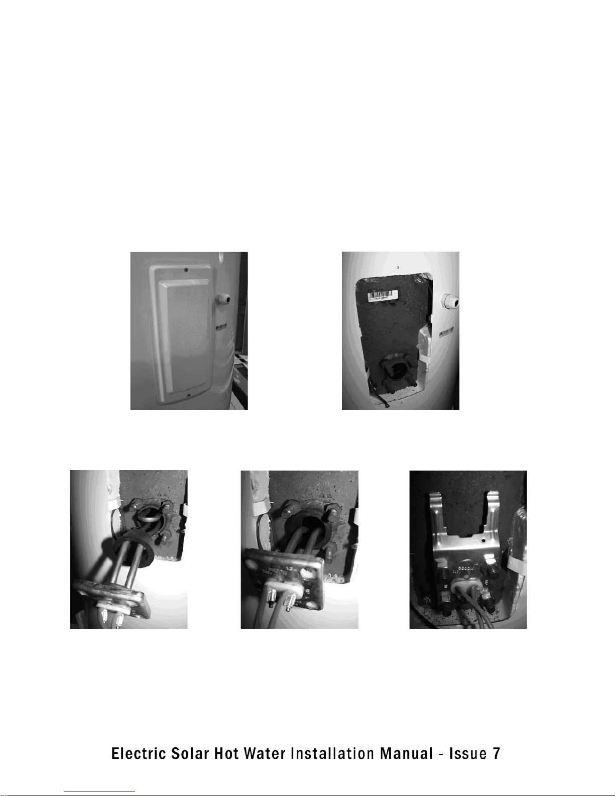
BOOSTER ELEMENT / THERMOSTAT / THERMOSTAT BRACKET - FITTING
7
Step 1. Remove the housing cover by removing 2 screws.
Step 2. Open housing with views of
4 mounting studs
Step 3. Insert element curve facing up
& with rubber seal loose on element
Step 4.Insert rubber seal between
element mounting studs.
Ensure it’s located properly into the tank.
Step 5. Attach thermostat bracket and
nuts. Tighten nuts securely & evenly.

G. HOT WATER STORAGE CYLINDER CONNECTION
G1 . SYSTEM CONNECTION REQUIREMENTS
The plumbing connection to the mains pressure supply line MUST include the following:
• Isolating valve
• Non return valve
OR a duo isolating non-return valve in lieu of two individual valves
• Pressure limiting or pressure reduction valve
• Expansion control valve
• Drain cock (some areas only)
• Disconnecting union
• Line strainer ( if required to filter large particulates only )
• Correct pipe size and specifications. Note that only dezincification resistant (DR) brass fittings can be used
for potable water plumbing.
Note for some States and local council areas: It is a local requirement that an expansion control valve be fitted
on the cold water supply line between the non return valve and the water heater. Check with your local authorities to see if this is required and fit according to local or State regulations.
8
Step 6. Push bracket towards inner tank to tension bracket
and clip thermostat under bracket in position.
The element, bracket and thermostat mounting is complete
Refer to G9 - Connection to Electricity for wiring diagram.

9
G2. ISOLATING / NON RETURN VALVES (OR DUO VALVES)
As water is heated it expands, and a mains pressure cylinder must have a NON RETURN valve fitted to prevent
water being forced into the cold inlet supply line. This is because when the water in the cylinder is heated it
expands and this increases the pressure inside the cylinder. It is IMPORTANT that this water does not flow back
into the mains water supply. The NON RETURN VALVE is located to the mains water line adjacent to the mains
water inlet to the cylinder.
An ISOLATION valve, also called a stopcock, is required to the cold water supply so the hot water system can be
isolated for maintenance and servicing.
A separate isolating valve is not required if a duo valve is employed.
Duo valves are used on the majority of mains pressure systems installed nowadays. This valve combines the
functions of an isolating valve when the handle is screwed down and a non-return valve when the handle is
screwed up. The washer section of the valve is spring loaded so that water pressure entering from the left of the
valve lifts the valve off its seat. When screwed down the valve cannot lift off its seat. Back flow (water entering
the valve from the right) is prevented. The spring holds the valve on its seat and the pressure of water forces it
to stay there.
The isolating valve effectively turns off the hot water system. It is installed on the cold supply therefore, will prevent hot water from leaving the storage cylinder of a mains pressure hot water system: no cold in, no hot out
G3. TPR VALVE
A TEMPERATURE PRESSURE RELIEF (TPR) valve MUST be fitted in all cases to the top of the cylinder to prevent
excessive pressure and Temperature build up. The TPR valve must be fitted with a permanently open copper
discharge pipe positioned facing downwards.
SAFETY WARNING: Manual operation of the TPR valve at least once every six (6) months is required to remove
lime deposits, ensure it’s continued correct operation and make sure there are no blockages. The valve and the
drain outlet pipe must not be sealed or blocked and must be permanently vented to the atmosphere
SAFETY WARNING: A 1000 kPa TPR safety valve MUST be fitted on ALL installations. NOTE that if an ECV valve
(Expansion Control Valve) is NOT fitted, then the TPR valve may drip during normal operation of the system
G4. PRESSURE LIMITING VALVE
A pressure limiting valve MUST be fitted on ALL INSTALLATIONS
The pressure limiting valve remains open until the upstream pressure approaches the valve pressure setting.
When the inlet pressure is above this, the valve acts as a reducing valve to keep the outlet pressure around this
level.
 Loading...