

Page 1

Page 2

Page 3

SUPPLY BY THE MANUFACTURER
The following Standard items are supplier to the Installer with each Our Solar Hot Water System
1. Storage tank
2. Flat plate solar collector (s)
3. Roof mounting system for Standard pitched roof installations
4. Roof mounting brass fittings kit including temperature well and air valve
5. Flow restrictor to suit either 1 collector or 2 collector system
6. Booster heating element Either 2.4 kw (250,300 litre tank) or 3.6kw (400 litre tank)
7. Thermostat
8. Thermostat mounting bracket
9. System controller
10. Circulation Pump
11. Housing for system controller and pump assembly
12. Pressure / Temperature Relief ( P / T ) valve
13. Additional valves may be provided by the manufacturer – Specific to client
14. Polyslab base.
SUPPLY BY THE INSTALLER
The following items are to be supplied by the installer
1. All labour required to fully install, test and commission the system
2. Copper piping ( DN15 ) to complete the installation
3. Thermal UV resistant insulation for all copper piping 13mm
4. Brass fittings including joiners, copper olives, elbows etc to complete the installation
5. Any additional valves or fittings required under local regulations
6. Electrical conduit, wiring, labels, sealants, screws and washers
7. Any other non Standard items required to complete the installation
NOTE: ALL VALVES SUPPLIED MUST BE INSTALLED
1
Page 4

INSTRUCTIONS FOR INSTALLERS
Installation of Solar Hot Water Systems must be in accordance with:
1. AS/NZS 3500.4 - National Plumbing and Drainage Code
2. AS/NZS 3000 – Wiring Rules
3. Local plumbing regulations
INDEX
SECTION PART ITEM DESCRIPTION PAGE
Section A Safety Information – WARNINGS 3
Section B Pre – inspection 4
Section C System Sizing 4
C1 Solar Hot Water Systems 4
C2 Storage tanks 4
C3 Collectors 4
Section D Types of Systems – Open Loop vs Closed Loop 5
Section E Hot Water Usage Patterns 5
Section F Tanks 5
F1 Tank Types 5
F2 Tank Sizes 5
F3 Tank Anodes 6
F4 Anode Replacement 6
F5 Tanks – How do they work 6
F6 Tank Position 6
F7 Heater Booster Element 7
Section G Hot Water Storage Tank Connection 8
G1 System Connection Requirements 8
G2 Isolating , Non Return valves or Duo Valves 9
G3 Temperature – Pressure Relief ( TPR ) Valve 9
G4 Pressure Limiting Valve 9
G5 Expansion Control Valve ( ECV ) 10
G6 Tempering Valve 10
G7 Drain Cock 11
G8 Line Strainer 11
G9 Connection to Electricity 11
G10 Insulation of Pipes 12
Section H Installation 12
H1 Collectors – Installation Requirements 12
H2 Pipe Lengths and Bends 13
H3 Roof Area Required and Weights of Collectors 13
H4 Collector Size and Packaging 13
H5 Installation of the collectors 14
H6 Inlet / Outlet Connections to Collectors 17
H7 Storage Tank Installation 19
H8 System Controller / Pump installation 20
H9 Mount Pump Box Assembly 21
H10 System Piping Connections 22
H11 Temperature Sensor Fitment 22
H12 Preliminary System Test 22
H13 Commissioning System 23
Section I System Maintenance / Periodic Inspections 25
I1 Valves and Fittings and Draining Tank 25
I2 Tank Anode replacement 26
I3 Replacement of the Electric Booster Element 26
I4 Replacement of Collector Glazing 26
I5 General Maintenance Tasks 26
I6 Contact Information 26
Warranty Information 28
2
Page 5

SAFETY INFORMATION
WARNING – OCCUPATIONAL HEALTH & SAFETY INFORMATION
Solar hot water systems can be heavy so always use approved lifting devices when installing a solar
systems. You MUST adhere to all Occupational Health and Safety requirements
WARNING – ONLY USE COPPER PIPES AND APPROVED COPPER FITTINGS. PLASTIC PIPES MUST
NOT BE USED IN THE INSTALLATION OF THE SOLAR HOT WATER SYSTEM
It is a requirement of a solar water heater installation that all pipe work be in copper and not plastic,
due to the effects of high water temperatures and pressures
WARNING – HOT WATER BURNS
Solar water heaters can generate water temperatures > 85°C, therefore, a tempering valve, or approved ‘mixing valve’ MUST be fitted to prevent water temperatures going to the home exceeding a
preset safe maximum. As a safety precaution, young children should always be supervised around
hot water fixtures as water temperatures over 50 degrees Celcius can cause scalding. Liquid from
the solar panels can be hot enough to create pressurized steam which can cause severe scalding. NO
MODIFICATIONS SHOULD BE ATTEMPTED by the homeowner. All work on the solar collectors, tank
or associated pipe work MUST be carried out by a licensed, authorized person
WARNING – INSTALLERS MUST exercise extreme care when installing or working on solar systems.
Our recommend solar panels are ALWAYS covered during installation
WARNING – It is a mandatory requirement of Australian Standard AS/NZS3500.4.2 that a suitably
approved temperature control device be fitted to the hot water supply for outlets used primarily for
personal hygiene. This valve should be checked regularly to ensure its operation and settings remain
correct. ALL systems must be installed with a Tempering valve
WARNING – DANGEROUS HYDROGEN GAS BUILD UP
If the hot water system is not used for a week or more, an amount of very flammable hydrogen gas
may accumulate in the tank. To dissipate this gas in a safe manner, it is recommended that a hot
water tap is turned on for a few minutes or until discharge of the gas stops. A sink or bath MUST be
used for this procedure, not an appliance such as a washing machine or a dishwasher. During this
procedure there should be no open flames, no smoking and no operation of an electrical appliance
nearby.
WARNING – TPR VALVE MUST BE FITTED
The temperature/pressure relief safety valve ( 1000 kPa ) supplied MUST be fitted to the top of each
storage cylinder with a permanently open copper discharge pipe angled downwards in a frost free environment. The valve MUST be operated every 6 months to remove any lime deposits and verify there
are no blockages. NOTE water may drip from this pipe during normal operation.
3
Page 6
PRE INSPECTION
• Are there tall trees or buildings that would shade the unit for all or part of the year? If so, the unit will not
function properly or perhaps even at all. The solar panels should be located in an unshaded position on the roof
at an angle which is as close as possible to the latitude position of the installation.
• Are there young trees or planned buildings that will shade a unit in the future? The homeowner should be made
aware that future shading of the panels will reduce the efficiency of the system.
• Is it possible to have the unit facing north or close to north? The panels should be located on a North facing
roof.
C. SYSTEM SIZING
C1. SOLAR HOT WATER SYSTEMS
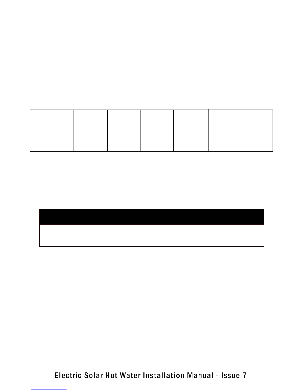
OZS251E OZS252E OZS301E OZS302E OZS402E OZS403E
Water Tank 250 Litre 250 Litre 300 Litre 300 Litre 400 Litre 400 Litre
Solar Collectors 1 2 1 2 2 3
Booster Electric Electric Electric Electric Electric Electric
C1. STORAGE TANKS
The size of the system involves the sizing of two components:
- hot water storage tank
- number of collectors
The number of litres of hot water used daily is the first calculation that needs to be made. This will vary enormously from family to family, a good estimate is 60 to 80 litres of hot water per person per day.
HOUSE NUMBER SUGGESTED SUGGESTED
SIZE PEOPLE TANK SIZE TANK P/N
1–2 bedrooms 1–2 250 litres 31.100.100
3 bedrooms 3–4 300 litres 31.100.101
4–6 bedrooms up to 6 400 litres 31.100.102
C2. COLLECTORS
Our Collectors have been specifically designed for optimal performance. Our Collectors are manufactured using
high quality materials. Each Collector has 8 x 10mm copper tube risers. Each Riser tube is welded to a high
efficiency TINOX coated fin to maximize absorption of heat from the sun and transmission of heat into the
water. The risers are welded to 22mm copper header pipes at the top and bottom to make a copper tube grid
which is encased in thick rockwool insulation. A special 4mm thick high impact glass is fitted to the front of the
Collector, an aluminium plate is fitted to the back and the Collector is fitted with a durable corrosion resistant
aluminium frame.
The very rough rule of thumb is that a 1m2 area of collector is required per person plus 1m2 for each major
appliance (e.g. dishwasher, washing machine) using hot water from the solar system. Our solar collectors are
approximately 2m2 in area.
The area of collectors required will be affected by shade particularly between 9am and 3 pm, whether the col-
4
Page 7
D. TYPES OF SYSTEMS – OPEN LOOP vs CLOSED LOOP
OPEN LOOP SYSTEM
In areas of frost, water may freeze in the collectors causing the collectors to rupture, The OPEN LOOP system
provides an AUTOMATIC FREEZE PROTECTION SYSTEM to prevent freezing and damage to the collectors. The
pump control system is automatically activated when the temperature gets too low. The system has been tested
and assessed against the freeze protection requirements Level 2, of AS2712, section 4.8. The activated pump
pumps hot water from the tank into the collectors when they are in danger of freezing therefore, ensuring the
collectors are not damaged.
CLOSED LOOP or indirect systems do not heat potable water directly. Instead, an anti-freeze solution circulates through the collectors, and then through a heat exchanger which transfers the heat to mains water. This
provides freeze protection and is also suited for use in poor water quality areas and frost prone areas. Closed
loop systems are more complex in design, more expensive and more difficult and time consuming to install. In
Australia, most systems sold to consumers are open loop as climatic conditions are favourable
E. HOT WATER USAGE PATTERNS
The time of use of the hot water from such a tank becomes significant. If the hot water is used at night the
boost electricity will bring the entire contents of the tank up to temperature.
If the hot water is used in the morning or during the day, and it is a sunny day, the solar input is likely to heat the
water so that little or no night boosting is required. This maximizes the efficiency of the system and minimizes
the requirement of additional heating from the booster.
F. TANKS
F1 – TANK TYPES
Basically there are 2 types of hot water tanks, Stainless steel and Vitreous enamel tanks
We only use Vitreous enamel tanks. We consider vitreous enamel to be the most appropriate lining of solar hot
water tanks under Australian conditions. The vitreous coating provides excellent corrosion protection by separating the steel tank lining from the water and it also insulates the tank. Vitreous tanks can withstand extremes
of temperature and are suitable for most water qualities with the Magnesium anodes providing additional protection to the effects of corrosion.
Vitreous enamel lined water heaters are suitable for water with a Total Dissolved Solids ( TDS ) rating of
2500mg/L or less. TDS (measured in mg / litre ) = Conductivity ( measured in Microsiemens) x 0.7
F2 – TANK SIZES
Our tanks come in 3 sizes, depending on the number of collectors required and volume of water required to be
stored. The tank sizes are 250 litres, 300 litres, 400 litres capacity
STORAGE TANK P/N CAPACITY HEIGHT ( TANK ONLY ) DIAMETER
31.100.100 250 litres 1353mm 620mm
31.100.101 300 litres 1572mm 620mm
31.100.102 400 litres 1629mm 710mm
5
Page 8
F3. TANK ANODES
TWO cast magnesium sacrificial anodes are connected to the inside of a storage tank from the top of the tank.
Magnesium is used because it is a more active metal than steel. The magnesium rod therefore acts as an anode,
by supplying electrons, and therefore sacrificing itself to protect the steel from corrosion. Therefore, over time,
the Magnesium anode corrodes and requires replacement.
STORAGE TANK P/N ANODE 1 ANODE 2
31.100.100 680mm 1045 mm
31.100.101 680mm 1275mm
31.100.102 680mm 1315mm
F4. ANODE REPLACEMENT
Replacement of the anode should be carried out at every few years. As a guide, the more dissolved solids in the
water, the faster the anode corrodes and the shorter the intervals should be between replacement. If the Total
Dissolved Solids (TDS, ppm) is > 1000, recommended anode replacement should be at 5 years. If the Total
Dissolved Solids (TDS, ppm) is < 1000 then replacement should be at 7 years.
F5. TANKS – HOW DO THEY WORK ?
Water is stored at MAINS PRESSURE which varies depending on the location of the installation. A minimum of
500 kPa cold water pressure is required otherwise mains pressure performance cannot be expected.
Cold water enters at the bottom of the tank, is stored until required. Hot water is drawn off from the top of the
tank. As this happens, more cold water enters to replace it. A non-return valve in the mains cold water connection prevents water returning to the mains water supply. To prevent damage to the cylinder, storage water heaters are fitted with a combination Temperature Pressure Relief (TPR) valve mounted at the top of the cylinder.
The relief pressure of the valve is the maximum pressure the heater is designed to withstand, and is known as
the working pressure or operating pressure. If the working pressure is reached (eg due to thermal expansion),
the valve releases some water to maintain the pressure at acceptable levels.
F6. CYLINDER - POSITION
By locating the cylinder as close as possible to points of use, you can minimize heat loss and hot water wasted.
Choose a position close to the most often used tap if possible. In most cases this position would be close to the
kitchen primarily followed by the bathroom. A site midway between these rooms would be ideal. The location
should be accessible for maintenance. The cylinders should be positioned so that the rating label can be read
and parts can be removed for service.
Interior cylinders
The National Plumbing and Drainage Code AS/NZS 3500.4 requires the fitting of a safe tray under a water
heater installed indoors in a concealed position. This safe tray must be connected to a drain that falls continuously to an approved termination point. It may be necessary to raise the cylinder onto a low stand. Ensure that
there is adequate floor support under the location selected. An electric-boosted cylinder will lose less heat if it
is enclosed in a cupboard, or isolated from draughts.
Exterior cylinders
It is usual to use a concrete plinth (paver) as a base for a cylinder that is mounted on the ground. For cylinders
located on sealed surfaces (bricks or concrete paths), provision must be made to accommodate the water that
escapes due to expansion through the pressure relief valve. A hole of 100mm diameter through the concrete
and filled with coarse gravel under the discharge pipe is acceptable. The plinth should be level and a minimum
of 50 mm above the ground level to prevent the water heater base being in contact with water for extended
periods.
Alternatively, Cylinders can be mounted on a plastic Polyslab base, which must be levelled correctly and fitted
in accordance with manufacturer’s instructions.
6
Page 9
F7. HEATER BOOSTER ELEMENT
Our single element mains pressure hot water storage cylinders have the element midway up the cylinder. The
element is required to boost the temperature of the water to a minimum of 60 degrees celsius. Our cylinders
have an adjustable thermostat which can be adjusted with a flat head screwdriver. This should only be performed by qualified persons. All heater boosters must be fitted with an isolating switch in the metre box during
installation.
WARNING: The element cover must only be removed by an electrician. The electrical power supply must be de-
activated at the main switchboard before the water heater electrical cover is removed.
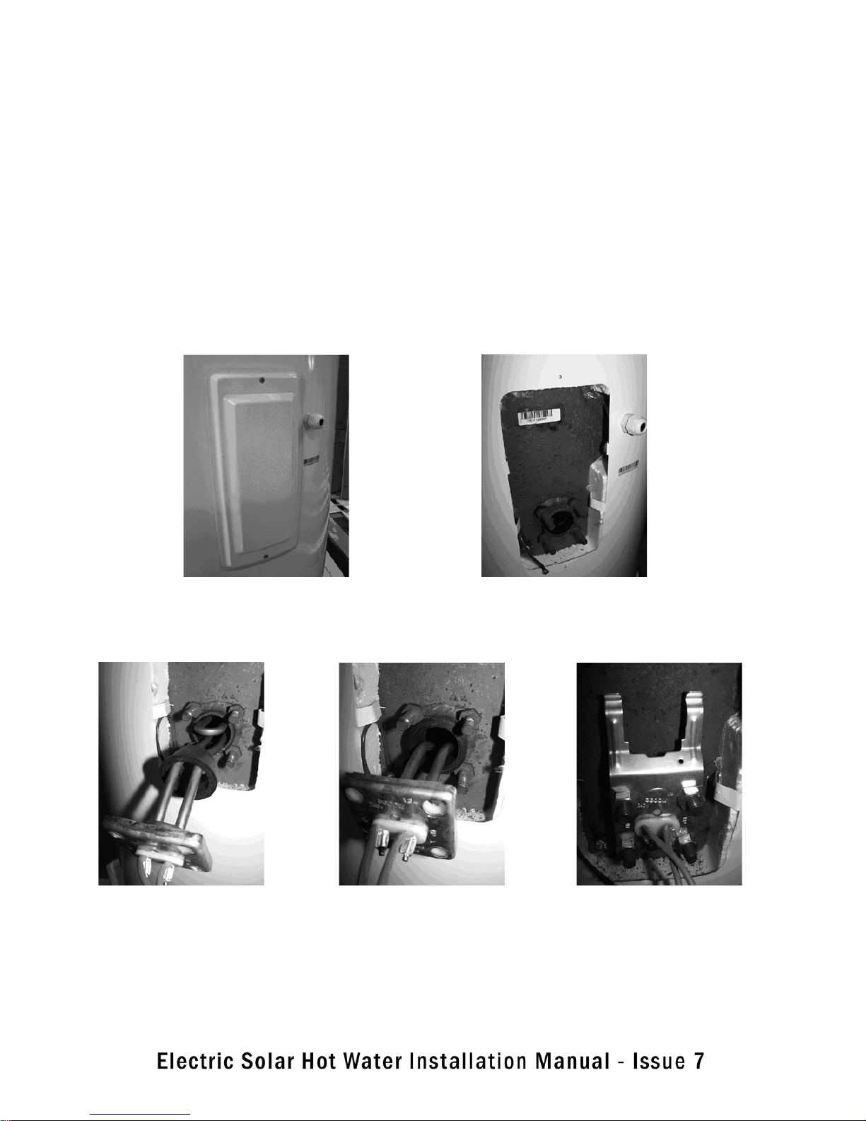
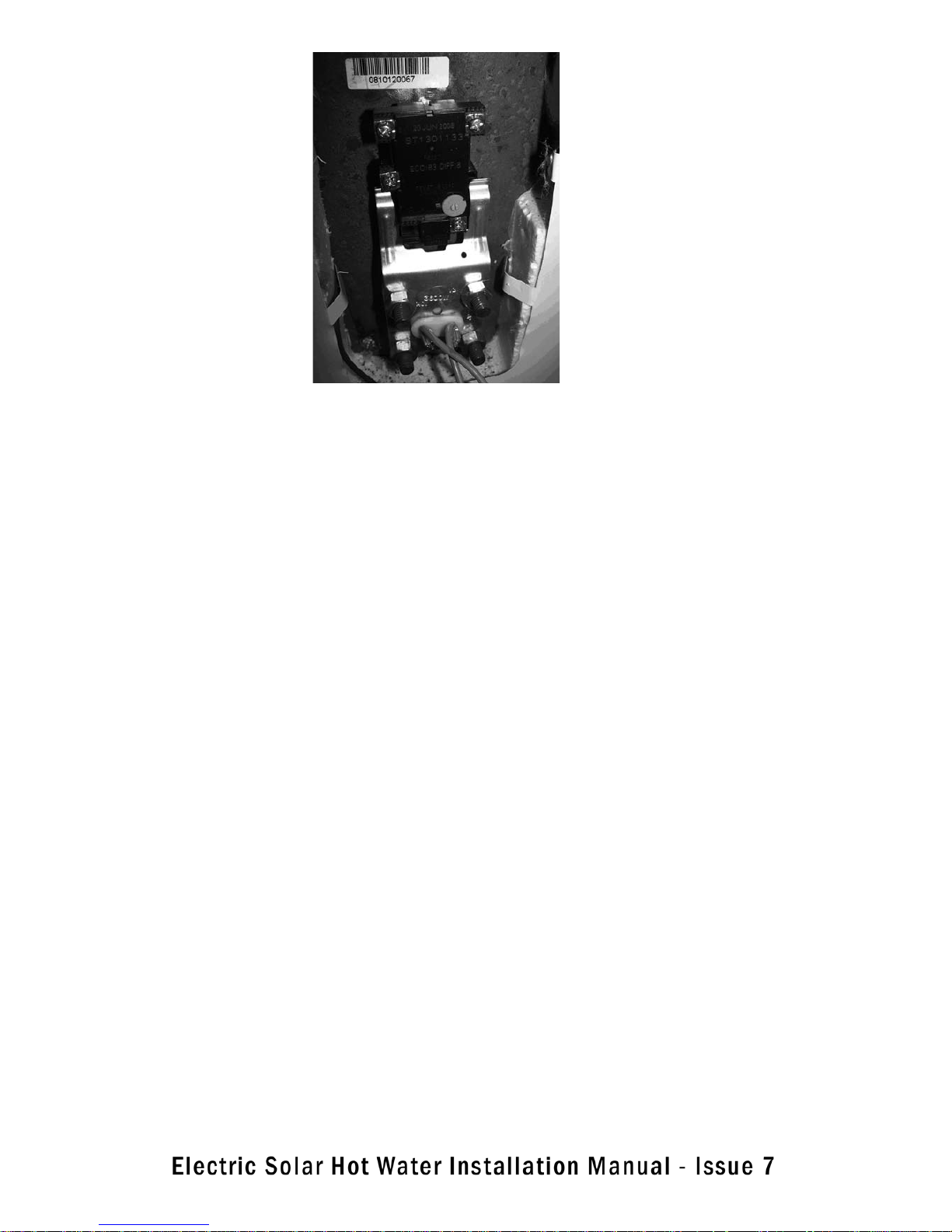
BOOSTER ELEMENT / THERMOSTAT / THERMOSTAT BRACKET - FITTING
7
Step 1. Remove the housing cover by removing 2 screws.
Step 2. Open housing with views of
4 mounting studs
Step 3. Insert element curve facing up
& with rubber seal loose on element
Step 4.Insert rubber seal between
element mounting studs.
Ensure it’s located properly into the tank.
Step 5. Attach thermostat bracket and
nuts. Tighten nuts securely & evenly.
Page 10
G. HOT WATER STORAGE CYLINDER CONNECTION
G1 . SYSTEM CONNECTION REQUIREMENTS
The plumbing connection to the mains pressure supply line MUST include the following:
• Isolating valve
• Non return valve
OR a duo isolating non-return valve in lieu of two individual valves
• Pressure limiting or pressure reduction valve
• Expansion control valve
• Drain cock (some areas only)
• Disconnecting union
• Line strainer ( if required to filter large particulates only )
• Correct pipe size and specifications. Note that only dezincification resistant (DR) brass fittings can be used
for potable water plumbing.
Note for some States and local council areas: It is a local requirement that an expansion control valve be fitted
on the cold water supply line between the non return valve and the water heater. Check with your local authorities to see if this is required and fit according to local or State regulations.
8
Step 6. Push bracket towards inner tank to tension bracket
and clip thermostat under bracket in position.
The element, bracket and thermostat mounting is complete
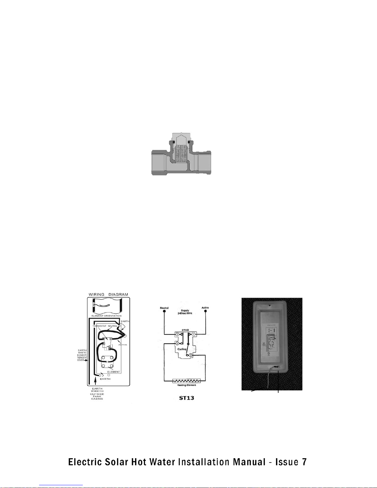
Refer to G9 - Connection to Electricity for wiring diagram.
Page 11

9
G2. ISOLATING / NON RETURN VALVES (OR DUO VALVES)
As water is heated it expands, and a mains pressure cylinder must have a NON RETURN valve fitted to prevent
water being forced into the cold inlet supply line. This is because when the water in the cylinder is heated it
expands and this increases the pressure inside the cylinder. It is IMPORTANT that this water does not flow back
into the mains water supply. The NON RETURN VALVE is located to the mains water line adjacent to the mains
water inlet to the cylinder.
An ISOLATION valve, also called a stopcock, is required to the cold water supply so the hot water system can be
isolated for maintenance and servicing.
A separate isolating valve is not required if a duo valve is employed.
Duo valves are used on the majority of mains pressure systems installed nowadays. This valve combines the
functions of an isolating valve when the handle is screwed down and a non-return valve when the handle is
screwed up. The washer section of the valve is spring loaded so that water pressure entering from the left of the
valve lifts the valve off its seat. When screwed down the valve cannot lift off its seat. Back flow (water entering
the valve from the right) is prevented. The spring holds the valve on its seat and the pressure of water forces it
to stay there.
The isolating valve effectively turns off the hot water system. It is installed on the cold supply therefore, will prevent hot water from leaving the storage cylinder of a mains pressure hot water system: no cold in, no hot out
G3. TPR VALVE
A TEMPERATURE PRESSURE RELIEF (TPR) valve MUST be fitted in all cases to the top of the cylinder to prevent
excessive pressure and Temperature build up. The TPR valve must be fitted with a permanently open copper
discharge pipe positioned facing downwards.
SAFETY WARNING: Manual operation of the TPR valve at least once every six (6) months is required to remove
lime deposits, ensure it’s continued correct operation and make sure there are no blockages. The valve and the
drain outlet pipe must not be sealed or blocked and must be permanently vented to the atmosphere
SAFETY WARNING: A 1000 kPa TPR safety valve MUST be fitted on ALL installations. NOTE that if an ECV valve
(Expansion Control Valve) is NOT fitted, then the TPR valve may drip during normal operation of the system
G4. PRESSURE LIMITING VALVE
A pressure limiting valve MUST be fitted on ALL INSTALLATIONS
The pressure limiting valve remains open until the upstream pressure approaches the valve pressure setting.
When the inlet pressure is above this, the valve acts as a reducing valve to keep the outlet pressure around this
level.
Page 12
G5. EXPANSION CONTROL VALVE (ECV)
Scale deposits in water can cause TPR valves to become blocked with carbonate deposits as the scaling water
passes through the hot valve body. To prevent failure of the TPR valve, cylinders installed in areas of high scale
must have an expansion control valve (ECV) fitted on the cold supply to the water heater. The ECV must have a
pressure relief setting lower than the TPR pressure relief setting but higher than the supplied water pressure.
In this way pressure is released through the ECV valve in preference to the TPR valve. As the ECV is fitted in the
cold mains water supply line, water is cold therefore, has less chance of forming scale and becoming blocked.
The ECV should be fitted after the non return valve
Note that AS 3500.4 lists the allowable pressure ratings of the valves.
An expansion control valve IS RECOMMENDED TO BE FITTED on ALL installations with a permanently open
copper discharge pipe angled downwards towards a suitable drainage point. Water will drip from this discharge
pipe during normal operation due to expansion of water in the system.
G6. TEMPERING VALVE
The Australian Standard AS NZS 3500 requires that water from a storage hot water cylinder at some stage
reach a minimum of 60°C in order to kill and prevent the further growth of Legionella bacteria. A solar hot water
system will not always reach 60°C without some form of boost heating.
Having heated the water to 60°C it is too hot to be safe for bathrooms etc., so it must be reduced in temperature
using a tempering (thermal mixing) valve. The location of the tempering valve is an issue. It is probably easiest
to install it right at the hot water storage cylinder (or continuous unit). This has the distinct disadvantage that
water to all points of the house will be tempered
SAFETY WARNING: A tempering valve MUST be fitted on ALL installations
10
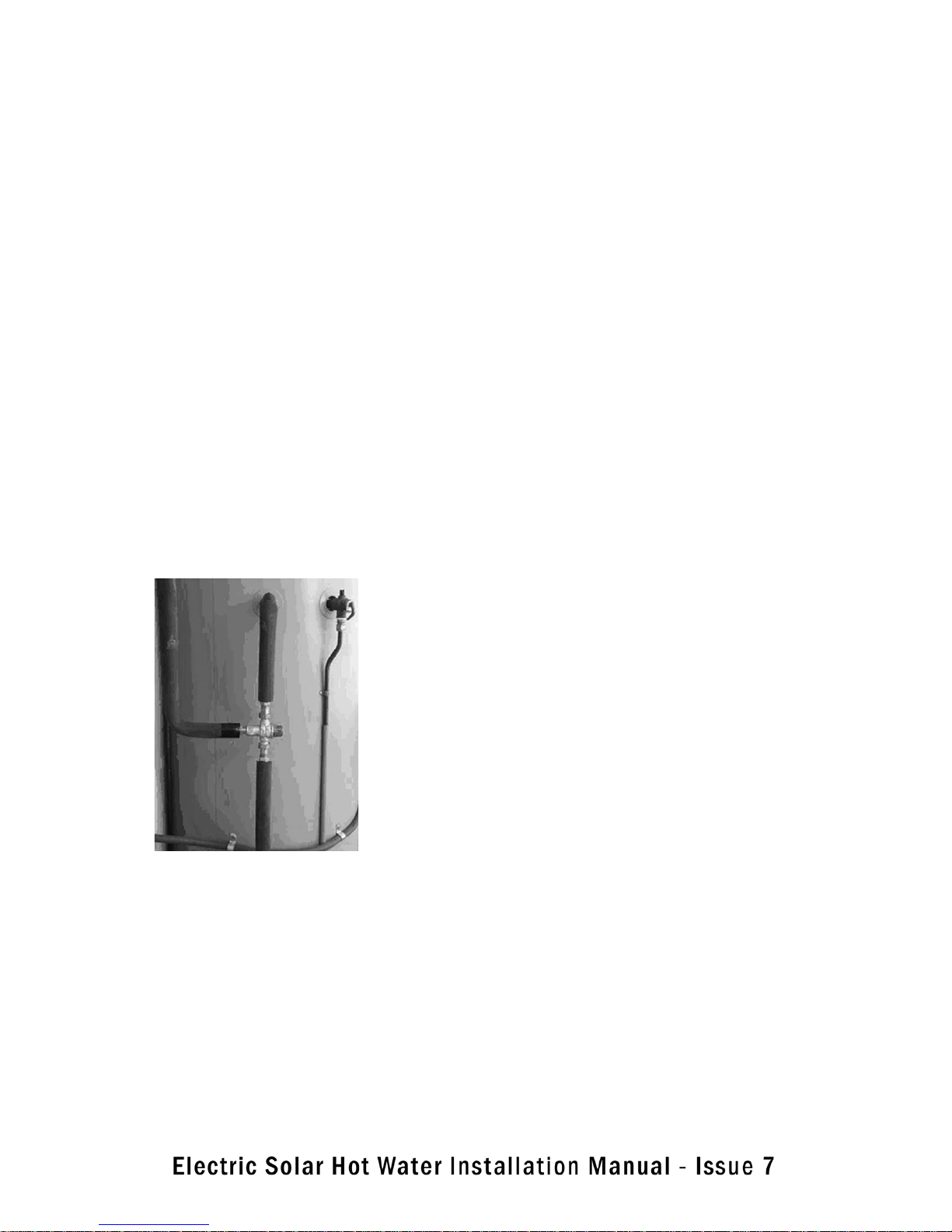
For many people, water in the kitchen for washing dishes or
in the laundry for washing clothes needs to be hotter than the
maximum 50°C to which the tempering valve is set. Two pipe
lines are now required, one for hot water (at least 60°C) and
one for tempered hot water (50°C). For supply to points a long
way from the hot water store, it is best to have the tempering
valve close to the point of use. If tempered water has to travel
a long distance it will continue to lose heat and be too cool by
the time it reaches its destination.
The pressure must be the same for hot and cold water on each
side of a tempering valve. There are different tempering valves
available for different operating pressures and of course different sizes for different flow rates. Make sure that the tempering
valve to be installed is suitable.
Figure1. A tempering valve attached directly to the cylinder. A second line is required if water in excess of 50 oC is required in the kitchen or laundry.
Page 13
G7. DRAIN COCK
A drain cock assists draining of the cylinder to remove sludge. Some areas of Australia require a drain cock to
be fitted in the cold water supply. Check with your local authorities
G8. LINE STRAINER
The line strainer filters out small particles. It is not a filter designed to hold back
fine particles. A line strainer is important where the water supply might have grit in it, but not all systems incorporate a line strainer.
Water enters from the left, through the bottom of the cylindrical stainless steel mesh screen, and passes
through the screen leaving behind particles that are too large to pass through the mesh. A line strainer is important with systems that have a pressure limiting valve. The close fitting moving parts of the pressure limiting
valve would be damaged by grit and prevented from functioning.
G9. CONNECTION TO ELECTRICITY
Electrical connections are for single phase 230 V ac 50 Hz. Connections to electricity MUST either be carried
out by a licensed electrician OR, depending on the electrical connections required, may be undertaken by a
Licensed plumber with a limited electrical license. Any electrical work MUST always be carried out by properly
licensed persons. Booster Heating elements require a 15 A service. The tanks have 2 green/yellow striped
earth wires – 1 connected from the inner tank to the outer tank and 1 connected to the booster electric element
housing. The earth wires are required to have excellent electrical contact with all surfaces and should also be
mounted with star shaped washers to scratch through any coating and provide perfect electrical contact.
WARNING – INSTALLERS / ELECTRICIANS MUST be properly qualified and licenced to carry out any electrical
work on the hot water system. UNDER NO CIRCUMSTANCES can electrical work be carried out without suitable
qualifications and the appropriate electrical licence
11
Electrical Diagram – Wiring Element / thermostat
Fix to inner earth
stud with
star washer
Fix with star
washer and
nut to cover
Label on inside cover of booster housing
Page 14

G 10. INSULATION OF PIPES
Insulation to pipework is required to reduce heat loss from hot pipes and in some localities cold pipes must be
well insulated, too, to prevent them from freezing.
The plastic insulation that comes on pre-lagged pipe does not provide adequate insulation for pipes that have
hot water in them for much of the day. The lagging, however, is satisfactory for pipes that are reburied in concrete or attached to a wall with saddles, permitting movement of the pipe within the lagging.
For pipes that have hot water flowing through them all day, such as those connecting solar collectors with a
storage cylinder, additional insulation is required. A functional and suited for purpose lagging must be used on
all hot water pipe work including flow and return lines.
H1. COLLECTORS – INSTALLATION REQUIREMENTS
All plumbing and other work must be carried out by a qualified person and in accordance with the National
Plumbing Standard AS/NZS 3500.4 and local authority requirements. If these instructions conflict with local
regulations then local regulations shall take priority
WARNING - Do not commence installation until all Safety issues related to the installation requirements includ-
ing lifting of modules onto the roof have been addressed.
1. The solar collectors should be installed facing North. If this cannot be achieved, orientation of the panels
up to 45 degrees from North is possible. However, it must be understood the efficiency of the system may be
reduced.
2. The collectors must be installed in a shade free position particularly between 9am and 3pm – the highest
solar input times. For maximum efficiency the collectors should be installed at a similar angle to the latitude of
the installation location. This will vary from place to place around Australia. Ideally, the collectors should be at
no more than 10 % more or less than the latitude angle for optimum performance. Collectors may be installed
at the roof angle for simplicity of installation and appearance, but must never be horizontal, as liquid shall not
circulate effectively and the collector glass will not self clean during rainy periods. As a guide, the collectors
should be installed with a minimum inclination of 10 degrees and a maximum inclination of 45 degrees
3. The solar hot and solar cold pipes between the solar storage cylinder and the solar collectors should be a
minimum of DN15.
4. The panel cold supply pipe connects from the storage cylinder cold inlet supply to the bottom of one of the
collectors via the circulating pump and the hot outlet pipe from the collectors connects to the cylinder’s solar
connection. The hot water sensor is connected at the outlet from the panel. All pipes must have a continuous
fall to their connections with the storage cylinder.
5. All pipes MUST be copper and fully insulated with appropriate insulation up to edge of the collectors. Insulation must be UV and weatherproof if exposed. All compression fittings must be brass or copper olives.
12
Page 15
6. The collectors should be located as close as possible to the storage cylinder to reduce energy losses. For
optimum performance the collectors should be no more than 20 m of pipe run from the cylinder, a total of 40
metres including return pipes.
7. The roof must be structurally able to support the weight of the collectors. Each collector weighs approximately 40 kg when full of water. If the roof cannot support the load, additional bracing must be installed before
the system is installed.
H2 – PIPE LENGTHS AND BENDS
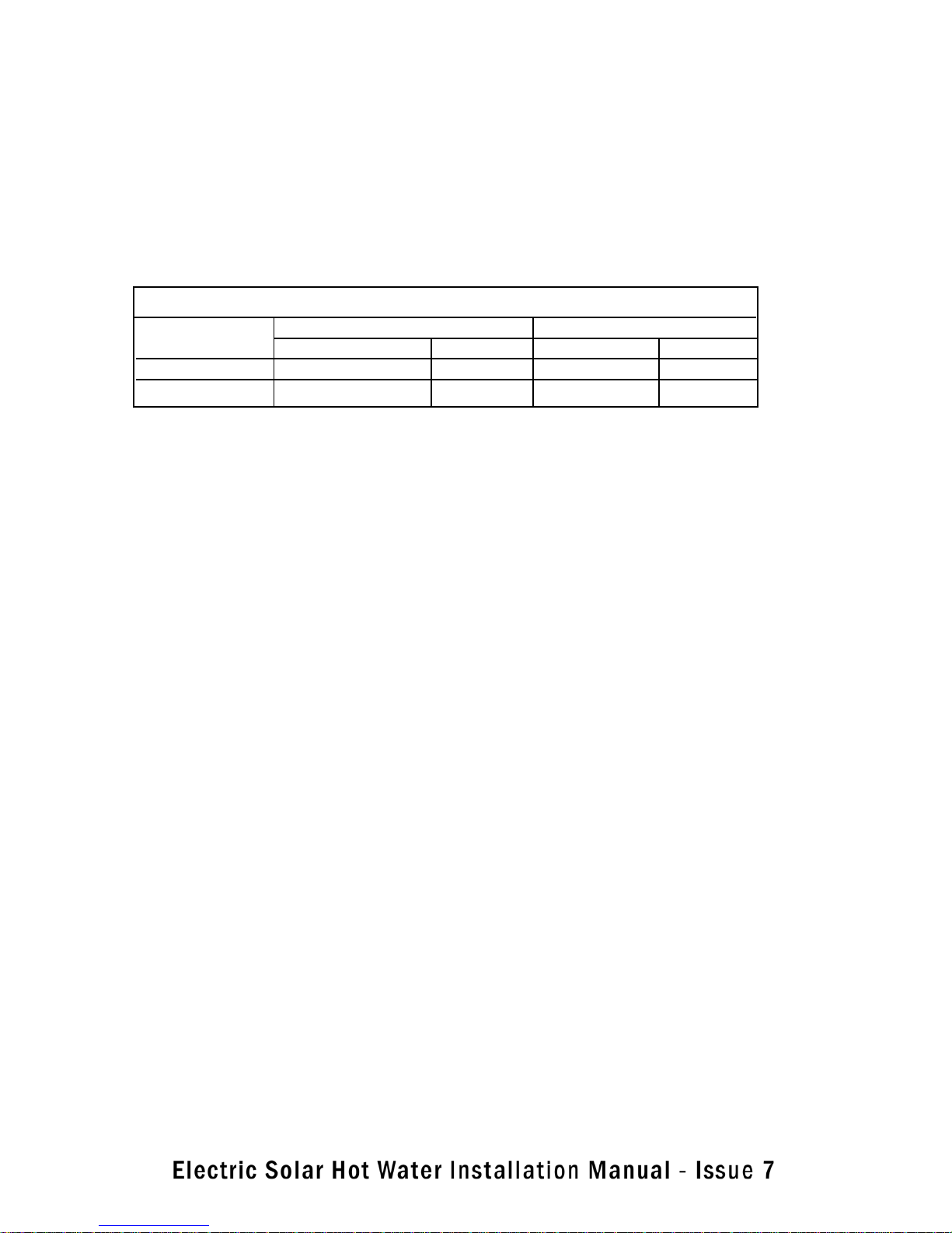
Maximum recommended pipe length and number of 90° bends
Pipe Size 1 or 2 Collectors 3 Collectors
Pipe Length 90° Bends Pipe Length 90° Bends
DN15 40 metres 20 30 metres 20
DN20 Not recommended NR 40 metres 20
Note: For each extra metre of pipe length, reduce the number of 90° bends by two. For each additional 90°
bend, reduce the maximum total pipe length by 0.5 metres. One 90° elbow equivalent to two 90° bends.
H3. ROOF AREA REQUIRED AND APPROXIMATE WEIGHT OF COLLECTORS
1 Collector 1.3 m wide x 2.0 m deep. Weight approximately 40 kg
2 Collectors 2.4 m wide x 2.0 m deep. Weight approximately 80 kg.
H4. COLLECTOR SIZE AND PACKAGING
Our Collectors are approximately 2 metres x 1 metre in size. In order to reduce damage and danger, the collector must be covered until it is filled with fluid and ready for use.
Each Collector is packaged in an individual cardboard carton.
It is recommended that the packaging on the front surface of each collector surface is left on the collector until
the system is filled with water. This shall prevent premature heating and possible danger of scalding of persons
adjacent to the collector part way through installation.
13
Page 16
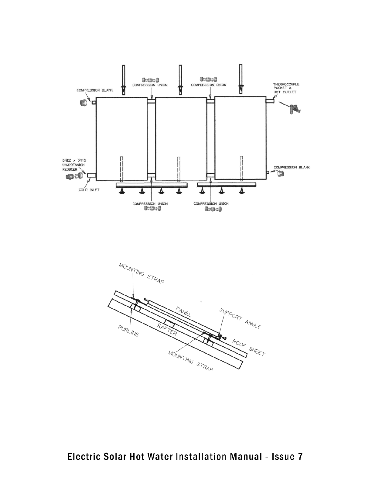
H5. INSTALLATION OF THE COLLECTORS
The procedure for solar collector installation is as follows:
1. Corrugated Iron Roof
Diagram of a Corrugated Iron roof
14
Page 17
For a single panel system – Corrugated Iron Roof
Attach the mounting straps onto the ends of the support angle.
Lay the angle on the roof in the selected position and attach the straps to the roof purlins.
Position the panel centrally on the angle and then attach a strap to the top edge of the panel and fasten it to
the roof.
For a two panel system – Corrugated Iron Roof
Select the most advantageous position for the panels on the roof.
Mark a point to represent the bottom left corner of the left hand panel at a position approx. 50mm below a
purlin.
Slide a mounting strap approx. 50mm onto left end of the angle and lay the support angle across the roof from
the marked point with a 15mm rise up to the right.
Adjust the strap along the angle so that it can be fastened down through the top of a sheet ridge into the purlins.
Slide the angle through the mounting strap to leave 50mm projecting on the left of the mounting strap.
Slide a mounting strap 50mm onto right end of the angle, and, maintaining a 15mm rise along the angle, fasten
the mounting strap down through top of a sheet ridge into the purlin.
Locate the left hand panel into its selected position. Slide the second panel along the support angle from the
right until its compression fittings register with those on the first panel. Tighten the compression fittings. Make
any required adjustment to the panel’s position and then attach them to the support angle with the supplied
screws.
Fasten a mounting strap to the middle of top edge of each panel with the supplied screws and then fasten the
mounting strap down through the top of a sheet ridge into the purlin.
For a three panel system – Corrugated Iron Roof
Attach the additional support angle to the right hand end of the second panel and then slide a mounting strap
50mm onto the right hand end of the angle.
Fasten the mounting strap down through top of a sheet ridge into the purlin.
Install the third panel as per the second.
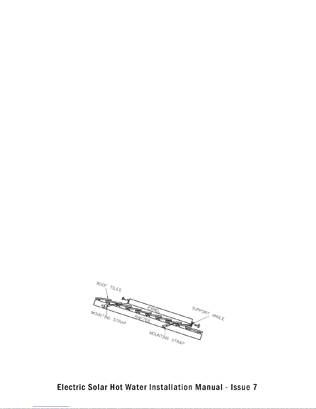
2. Tile Roof
Diagram of a Tile roof
15
Page 18

Select the most advantageous position for the panels on the roof that spaces the panels equally about roof rafters. Mark a point on the nose of a tile in line with the left hand rafter to represent the bottom of the left hand
panel
For single panel system.
Select a position for the panel which spans 3 rafters and mark a spot on a tile, just above its nose, which represents the bottom left corner of the panel.
Remove two tiles above the one which was marked over the left hand rafter. Repeat this at the right hand rafter.
Slide a Mounting strap onto each end of the support angle and attach the left hand one to the rafter.
Set the angle to a 10mm rise and attach the right hand strap to the rafter. Refit the tiles.
Sit the panel onto the support angle and centralize it. Attach the panel to the angle with the screws provided.
Attach a mounting strap to the centre of the top of the panel.
Remove two tiles from beneath the strap and fasten the strap to the rafter.
Refit the tiles.
For two panel system – Tile Roof
Remove two tiles above the one that has been marked. Remove another two tiles, at the same height as the first
two, from above the rafter which is 1800mm to the right
Slide a mounting strap onto each end of the support angle and attach them to the exposed rafters so that there
is a 15mm rise along the angle. Note that the straps may need to be twisted below the level of the tiles and be
attached to the side of the rafter if there is insufficient room on top of the rafter.
Refit the tiles. Set the panels onto the support angle, centralize them, and tighten up the compression unions
between them.
Using the screws provided, attach the support angle to the panels.
Remove two tiles from above the rafter at the top of each panel.
Attach a mounting strap to the panel in line with the rafter and then attach the straps to the rafters.
Refit the tiles.
For three panel system – Tile Roof
Duplicate the above procedure for the first two panels and then attach the support angle extension to the bottom of the second panel with a 100mm overlap.
Remove two tiles from above the rafter which the extension crosses. Slide the mounting strap onto the support
angle and attach it to the rafter as above, maintaining the upward slope of the support rail.
Refit the tiles and slide the third panel along the rail into contact with No. 2 panel and tighten the compression
unions.
16
Page 19
Attach the panel to the support rail.
Repeat the tile removal and strap attachment at the top of the panel.
Note that on all installations the excess strap above the panels should be removed for a neat and professional
appearance
H6. INLET / OUTLET CONNECTIONS TO COLLECTORS
Slide a 22 mm Compression Plug assembly to the top left and bottom right header tube projections of the
panel array. Tighten the assembly taking care not to twist the copper tubes of the collector. Make sure you use
correctly sized spanners and that the plug is held steady whilst the compression plug is tightened.
Inlet (cold water) Connections to Collector Array
Slide the DN 22 to DN 15 Compression Union Assembly onto the bottom left header tube projection of the collector array. Tighten the assembly taking care not to twist the copper tubes of the collector.
Outlet (hot water) Connections to Collector Array
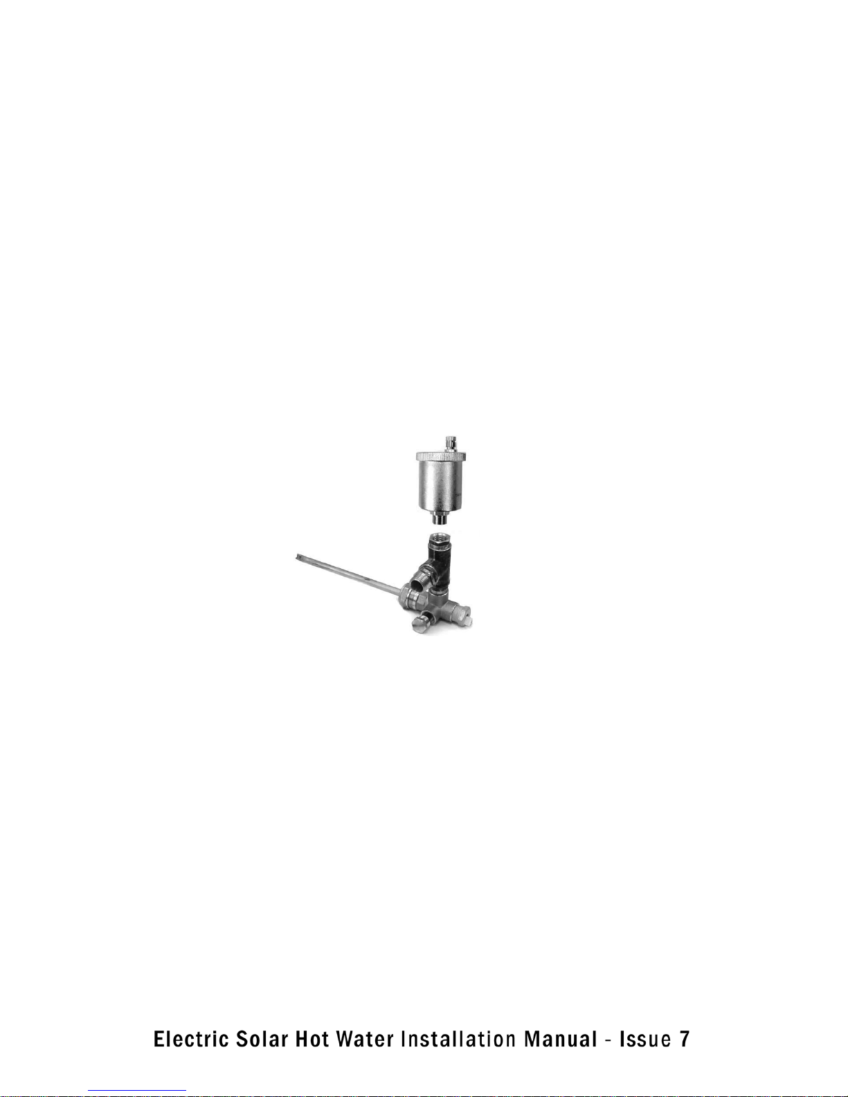
Assemble and install the Hot Connection Thermocouple Well assembly to the hot water outlet of the last panel
in the array as follows:
Hot Thermocouple Well Assembly with Air Bleed valve
a. Take the temperature well and slide it onto the copper spigot at the top right of the collector array with its
tee pointing upwards. Screw nipple into the tee and then another tee facing out with another nipple.
Screw the Reducing Brush into the top of the tee and then fit the air bleed valve into the top of the tee.
Tighten the assembly taking care not to twist the copper tubes of the collector. Make sure you use
correctly sized spanners and that the outlet assembly and blanking plugs are held steady whilst the
compression nut is tightened.
b. Apply thread tape or suitable sealant onto the 1/2” BSP thread of the Temperature Well.
c. Insert the Temperature Well into the 1/2” BSP socket at the end of the Hot Connection Union and tighten
normally. Take care not to over tighten.
The collector array is now completed and ready for connection to the water heater system
(FOR ILLUSTRATION PURPOSES ONLY)
17
Page 20
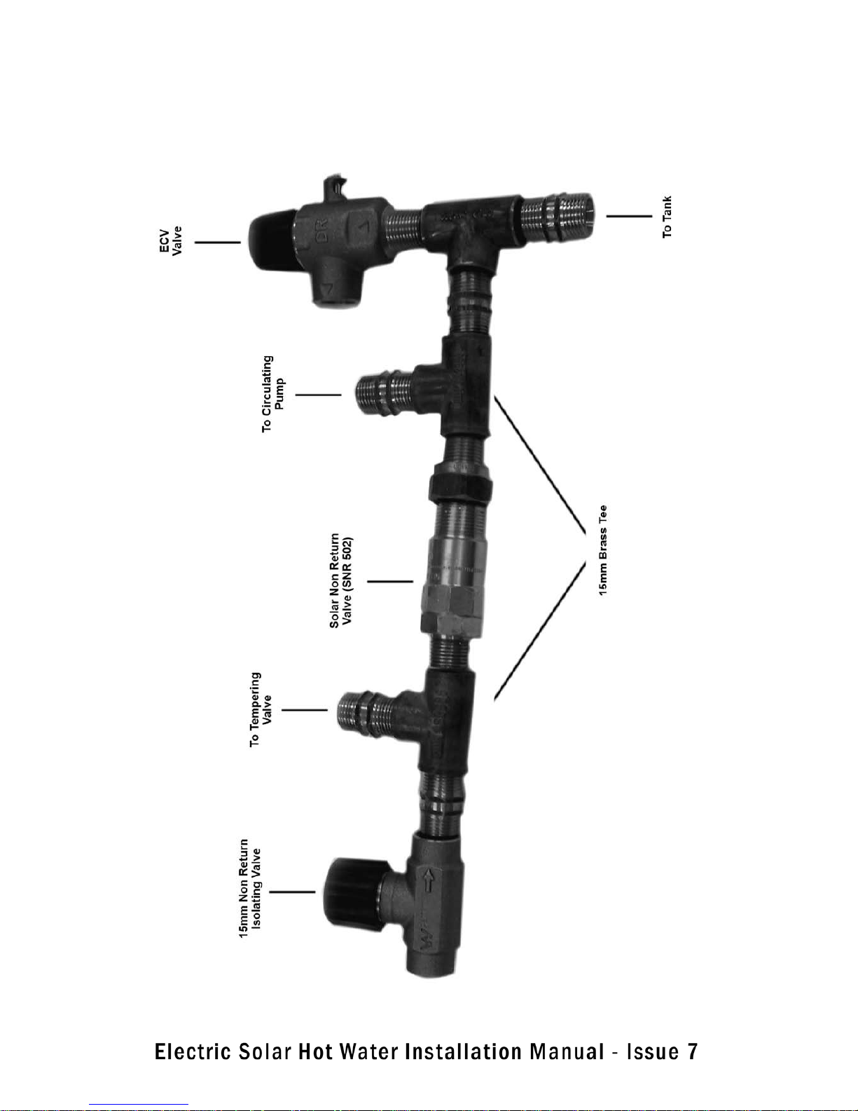
(FOR ILLUSTRATION PURPOSE ONLY)
‘Cold Water Valve Train Connections to Storage Tank’
18
Page 21

H7. STORAGE TANK INSTALLATION
IMPORTANT: Refer to Diagram – “Cold Water Valve Train Connections to Storage Tank”
Select the location of the storage cylinder to suit the panel and most frequently used hot water taps.
Connect the cold water supply to the cylinder inlet utilising a stop valve, non-return valve, pressure reducing
valve and, if required (listed in AS 3500.4 and local regulations), a cold water expansion valve.
Connect the hot outlet of the panels to the solar inlet on the cylinder.
Install the Pressure Relief ( P & T ) valve into the fitting on the top of the cylinder and run a ½˝ copper drain
line from the valve to a safe discharge point angled downwards. The drain line MUST be permanently open to
the atmosphere and MUST be unobstructed at all times. The Pressure relief valve MUST be operated every 6
months to remove lime deposits and verify no blockages. NOTE that water may drip from the pipe during normal
operation if an ECV (Expansion Control Valve) is not fitted to the system.
Open the discharge of the valve to prevent any premature pressure build up in the cylinder.
Connect the cylinder’s hot water outlet to the hot connection on a tempering valve and the tempering valve’s
outlet to the property’s hot water piping. Connect a cold water line from the cold valve train to the cold connection of the tempering valve.
19
Page 22
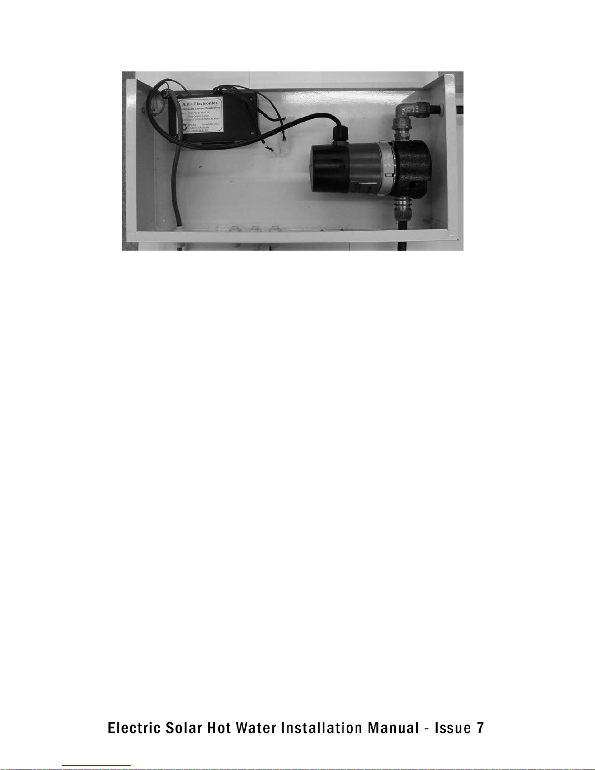
H8. SYSTEM CONTROLLER / PUMP INSTALLATION
Diagram – System Controller / Pump Assembly for Open Loop System – 1 or 2 solar collectors
The use of a pump and system controller requires that the pump, controller electrical inputs and outputs including the temperature sensors are all correctly installed. There are a few general principles to be followed
when installing a pump-circulation solar system
• The pump must be mounted the correct way with water input on the input flow side of the pump and water
output on the output flow side of the pump. An arrow on the pump shows the direction of water flow. The pump
and pump assembly MUST be mounted with the discharge upwards, making it easier for air to escape from
inside the pump.
• The pump should be on the flow line to the collectors so that it pushes the water through the collectors, not
on the return line where it would be pulling (sucking) the water from the collectors. On the return line it would
be likely to cavitate causing noise and damaging the pump.
• The rate of circulation should not be too high (Approx. 0.2 l/min/m²), otherwise there will be excessive turbulence (stirring up of the hot and cold layers of water) within the storage cylinder. This reduces the efficiency
of the solar collectors. A restriction valve is required to be fitted to reduce flow rates on some systems. These
must be correctly fitted on the outlet side of the pump assembly
The wire to the sensor in the collector header should be covered to protect it from physical damage and damage
from UV light where it is exposed. Flexible electrical conduit serves this purpose well.
• The ‘hot’ sensor must be situated at the hottest water in the collectors and the ‘cold’ sensor at the bottom of
the storage cylinder, on or near the cold supply line. Another temperature sensor is provided which is fitted part
way up the tank which shows the temperature of the hot water in the tank.
20
Page 23
H9. Mount Pump Box Assembly
Mount the Controller/Pump box on a wall at a convenient position for piping and wiring. Ensure 4 plastic spacers are installed behind the box so that it sits away from the wall and allows the lid to be fitted.
Place the pump inside the box and attach copper pipes to both connections so that they project through the
grommets.
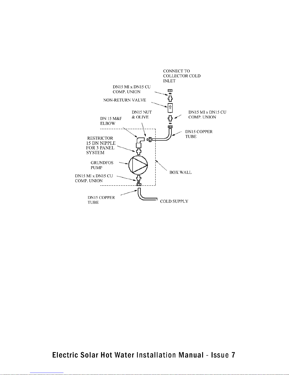
Diagram – System Piping and Fittings
21
Page 24
H10. SYSTEM PIPING CONNECTIONS
Connect the piping and fittings as shown in the diagram. Run DN 15 copper tube up to the collector’s cold inlet
from the pump outlet. Run DN 15 copper pipe from the panel’s hot outlet to the cylinder’s solar return connection.
IMPORTANT NOTE: Copper pipes MUST slope upwards to the collectors. If the pipes do not continuously run
on an upwards slope towards the collectors then this will prevent the system evacuating all the air and will
therefore prevent the water from circulating.
H11. Temperature Sensor Fitment
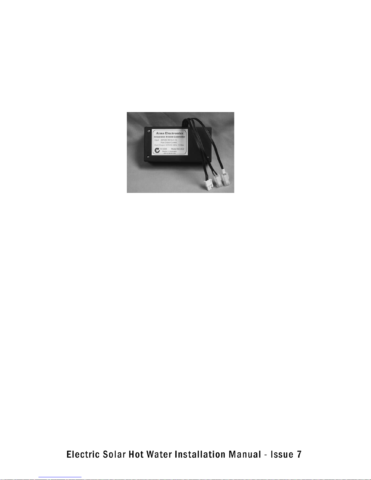
The System Controller is supplied with three sensor leads, one long and two short. Unroll each lead in turn and
pass it through a small cable gland from the inside of the housing to the outside.
Connect the sensor leads to the System Controller – ensure that the short lead with the white end uses the connector with the white band.
The long sensor lead is used to sense the temperature at the top of the collector. The short lead with the black
end is used to sense the temperature at the bottom of the storage tank. The short lead with the white end is
used to sense the temperature at the middle of the tank. Install all sensor leads carefully so as to avoid damage
to the cable or the sensor.
Install the thermocouple sensors into their respective sockets on the cylinder and panels. Do not seal the sockets at this stage.
The sensor leads may be extended if required using suitable cable. Ensure that wires are properly insulated.
Connections should be made using solder and insulated with heatshrink to provide good mechanical support
and waterproofing.
H12. Preliminary System Test
When all connections have been tightened the system can be tested for pressure tightness.
Check for leaks.
A preliminary test may now be performed.
22
Page 25

Disconnect the long sensor lead at the system controller. Apply power to the system. After 10 to 12 seconds the
control output relay should click and switch the pump on. It can be difficult to detect if the pump is running, it
can run quietly and with little vibration. There is a green light on the pump that illuminates when the pump is
powered, but this is difficult to see.
If there is sufficient sun, hot water will be circulated back to the tank when the pump is running, check the
return line from the collector with caution, it may be very hot.
Remove power and reconnect long sensor lead after test.
Seal sensors in their sockets and secure wiring. The installation is now complete.
Show the customer the control system and then replace the control box cover. Secure the cover with self tapping screws with star washers.
Install the heater booster element and thermostat securely using the rubber flange provided for a water tight
seal.
Connect the wiring after confirming that the electrical circuit is isolated.
WARNING – ENSURE ELECTRICAL CIRCUIT IS ISOLATED BEFORE CONNECTING ANY ELECTRICAL WIRING
Open some convenient hot taps in the house and then open the cold water valve to allow the cylinder to fill.
When air free water is discharging from the taps and NRV then close them and allow the pressure in the cylinder
to stabilise.
Check for leaks throughout the system and correct as required
H13. COMMISSIONING THE SYSTEM
• Follow the procedures for installation of the storage tank, the solar collectors and the system controller /
pump assembly
• Ensure all valves and connections in the system are secure.
• Turn the cold water ON so that the storage cylinder fills and ensure the cap on the automatic air vent is OPEN
(approx. 1½ turns) during the filling process to ensure the panels are completely vented of air. Ensure there is
no air
• When no more air is escaping from the vent then the system is full. The cap on the air valve should then be
CLOSED.
• the TPR (temperature pressure relief) valve should be checked and operated to release air.
• hot water taps within the house should be turned on until water free of air bubbles is delivered.
• any taps with strainers or aerators on their outlets should have the strainers/aerators taken off and cleaned
to remove any swarf or other debris that has got into the system during installation.
23
Page 26

• the whole system should be checked for leaks.
• the storage cylinder and collectors should be checked to ensure that they sit properly in place
• Once these checks have been carried out and there appears to be no reason to drain the storage cylinder, the
cardboard cover(s) can be removed from the collectors.
• if it is a sunny day, the hot pipe leading from the collectors to the storage cylinder should be checked (by
hand) to ensure that it is heating up; it should be hotter than the cold line from the storage cylinder to the collectors.
• The operation of the pump can be tested by partially immersing the thermocouple sensor that goes into the
top header of the collector into hot water to see if it causes the pump to switch on. If it is cooled, the pump
should switch off. If the sensor is placed under very cold conditions (an ice block might be cold enough to simulate frosty conditions) the pump should again come on to provide frost protection. Frost protection commences
through operation of the pump at 4 degrees celcius.
• the sensor associated with the bottom of the storage cylinder can similarly be tested; if it is heated it should
turn the pump off.
• the manual override knobs on the TPR (temperature pressure relief) on the storage cylinder and ECR (pressure relief) valve on the cold supply of a mains pressure unit should be SLOWLY checked to see that each discharges normally and does not drip at the completion of the test.
• Check that the element operates. The power indicated by the meter, when comparing the element turned on
and turned off, shall confirm this.
• Ensure the thermocouple leads are fully inserted (maximum distance in) into the receptacles in the tank and
the collector. Seal the thermocouple sensors into the tank and the collector array using a suitable waterproof
sealant.
• The system should now be operational and fully functional.
24
Page 27

I. System Maintenance / Periodic Inspections
I1. Valves / Fittings & Draining the tank
- The Pressure / Temperature ( P / T ) safety relief valve is mounted on the top of the storage tank. This valve
should be opened and checked every 6 months by releasing the valve ( see Caution information below ). This
flushes any lime deposits out of the valve which can clog it and make it not function correctly. Allow hot water to
flow through the valve briefly to ensure correct operation and clean the valve. It is recommended that the valve
is replaced every 5 years
CAUTION – HOT WATER will flow out of the discharge pipe connected to the valve when released. Ensure that
you avoid any contact with the hot water to prevent scalding
NOTE : If a Expansion Control Valve ( ECV ) has not been fitted then it is normal from time to time for a small
amount of water to drip from the discharge pipe connected to the P / T valve
- Check all other valves and copper fittings to ensure there are no leaks. NOTE : It is normal for water to drip
from time to time from the discharge pipe connected to the Expansion Control Valve ( ECV ). This drip is due to
expansion of hot water in the system which may exceed the setting on the ECV
Draining the tank
The tank may need to be drained from time to time for maintenance reasons
CAUTION: The tank MUST be completely electrically isolated from the Mains power supply PRIOR to draining
water. HOT WATER will flow out of the drain nut when it is removed. Ensure that you avoid any contact with the
hot water to prevent scalding
CAUTION: Draining of the tank MUST be done by a qualified person only. The homeowner should NOT ATTEMPT
to drain the tank
Each tank is equipped with a drain hole at the bottom of the tank marked “Drain” The brass fitting should be
slowly opened to release water from the tank – CAUTION HOT WATER BURNS. A tap should be opened inside
the home to release the pressure in the system to ensure that the water drains properly from the tank.
25
Page 28

I2. Tank Anode replacement ( Refer Section F4 )
CAUTION : Tank anode replacement MUST be done by a qualified person only. The homeowner should NOT AT-
TEMPT to replace the anodes
Sacrificial magnesium anodes are inserted in all Our storage tanks and these preferentially corrode to increase
the lifespan of the tank. Eventually these anodes can wear away and require replacement
Replacement of the anode should be carried out approximately every 5 years. There are 2 anodes, both anodes
should be replaced at the same time. The anodes are located under 2 plastic covers on either side of the T / P
valve located on the top of the tank.
CAUTION : The tank MUST be completely drained empty of water and completely electrically isolated from the
Mains power supply PRIOR to replacing the anodes
The anodes can be carefully drawn out by unscrewing the 2 nuts which are part of the anodes at the top of the
tank and lifting them out through the top of the tank. Depending on the location of the installation, it may be
possible to remove the anodes without moving the tank. If there is insufficient height above the tank to safely
remove the anodes then the tank may need to be moved so there is sufficient room to carry out the process
I3. Replacement of the Electric Booster Element
CAUTION : Electric Booster replacement MUST be done by a qualified person only. The homeowner MUST NOT
ATTEMPT to replace the electric element. The system must be COMPLETELY electrically isolated and drained
of water before replacing the element
On 250 litres and 300 litres storage tanks, the booster element must be replaced with a 2,400 watt booster element. On 400 litre storage tanks, the booster element must be replaced with a 3,600 watt booster element
Section F7 explains how the booster element is fitted. Removal of the element is the reverse of this operation.
Care should be taken when removing the old element to prevent damage to the threads of the 4 locating pins.
In addition, care should be taken to ensure the pins are not damaged or bent.
SAFETY WARNING : Extreme Caution should be taken when replacing the glazing of the collectors. This presents
a significant hazard and is recommended to be undertaken by a Our Solar authorized technician.
I4. Replacement of Collector Glazing
SAFETY WARNING: Extreme caution should be taken when replacing the glazing of collectors. This presents a
significant hazard and collectors must only be replaced by one of our authorized technicians.
I5. General Maintenance Tasks
The SOLAR COLLECTORS generally do not require maintenance. However, they do need to be kept clean to
maximize performance. It is recommended that periodically, depending on dust / dirt which may have settled
on the collectors, the collectors should be wiped down with a cloth and warm soapy water followed by rinsing
with water.
I6. Contact / Service information
Ozroll Industries
174 Cavan Road
Dry Creek SA 5094
Ph: (08) 8368 0263
www.ozroll.com.au
INSTALLER – PLEASE EXPLAIN TO THE CUSTOMER HOW THE SOLAR HOT WATER
26
Page 29
THE INSTALLATION IS COMPLETE
INSTALLER – PLEASE EXPLAIN TO THE CUSTOMER HOW THE SOLAR HOT WATER
SYSTEM WORKS AND ANSWER ANY QUESTIONS THEY HAVE ABOUT THE
OPERATION OR MAINTENANCE OF THEIR NEW PRODUCT
THANK YOU
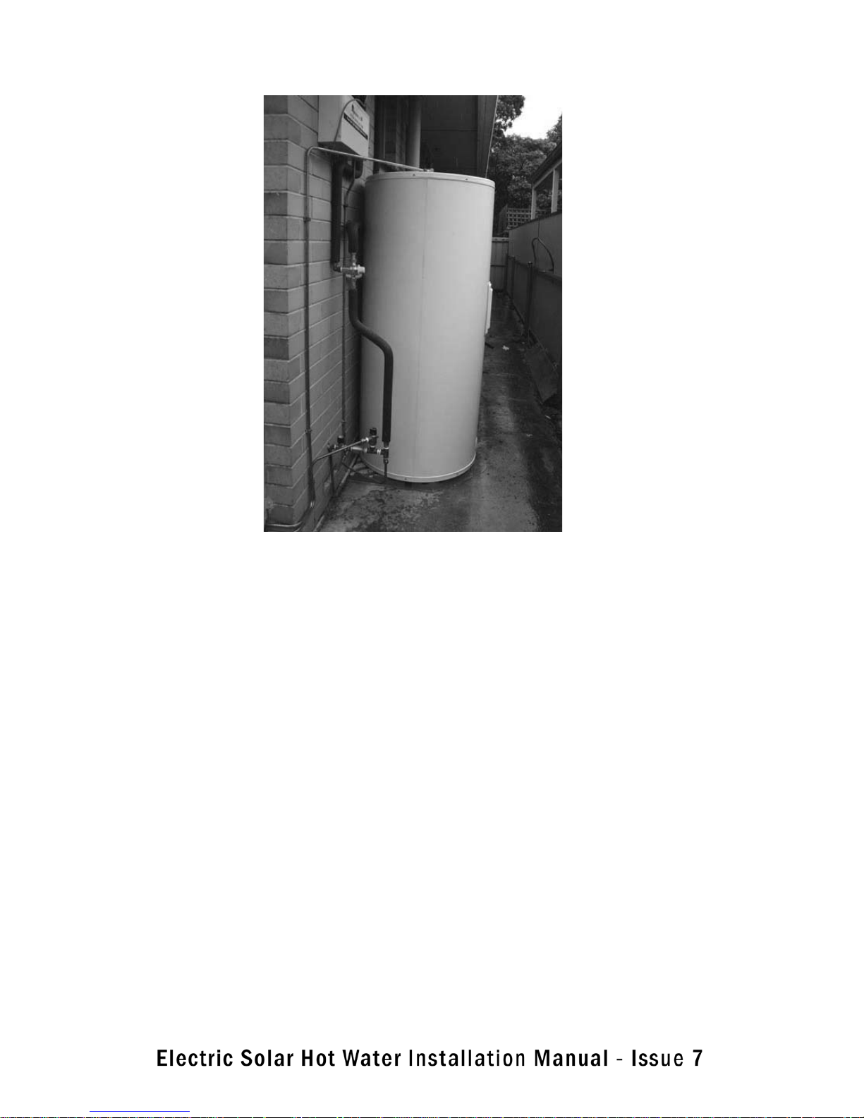
We recommend the appearance to be of a
neat and tidy installation shown above.
27
Page 30

WARRANTY / GUARANTEE
TERMS AND CONDITIONS
A SOLAR HOT WATER SYSTEM INCLUDES A COMPREHENSIVE 1 YEAR PARTS AND LABOUR
WARRANTY ON THE SOLAR HOT WATER SYSTEM. IN ADDITION, OUR GUARANTEE TO REPLACE YOUR HOT WATER TANK IF THE INNER CYLINDER FAILS OR YOUR SOLAR COLLECTORS FAILS WITHIN A 5 YEAR PERIOD FROM THE DATE OF INSTALLATION.
• VITREOUS ENAMEL TANK
• COLLECTORS
• CONTROLLER
• SOLAR PUMP
• VALVES & FITTINGS
WARRANTY – 1 YEAR
1. All Our solar hot water systems including components are covered by a 1 year warranty
against defective factory parts or workmanship from the date of installation.
2. We will repair or replace the failed components free of charge unless the place of installation is more than 50 km from a our office in which case a transport fee shall apply
3. The warranty applies only to defects or damage which have arisen solely due to faulty materials or workmanship, including installation
4. The warranty covers either repair AND / OR replacement of failed components and the decision is made entirely at our discretion.
GUARANTEE – 5 YEARS
5. If the inner cylinder of the storage tank fails after the 1 year warranty period but within 5
years of the installation date then we will provide a replacement storage tank. All costs associated with removal of the failed tank, pick up of the new tank from a our office and installation
including all labour costs and material costs shall be entirely at the expense and responsibility
of the owner of the hot water system
6. If a Collector fails after the 1 year warranty period but within 5 years of the installation date
then we will provide a replacement Collector. All costs associated with removal of the failed
Collector, pick up of the new Collector from a our office and installation including all labour
costs and material costs shall be entirely at the expense and responsibility of the owner of the
hot water system
Page 31

WARRANTY / GUARANTEE
TERMS AND CONDITIONS
SCOPE OF WARRANTY AND GUARANTEE
7. The warranty and guarantee ONLY APPLY to defects or damage as a direct result of faulty
factory parts or workmanship
8. The warranty and guarantee DO NOT APPLY to Collector glass
9. The warranty and guarantee DO NOT APPLY to defects or damage caused by or resulting
from:
a) Accidental damage,
b) Misuse or abnormal use of the system including neglect of any kind to the system
c) Poor water quality including water contamination
d) Excessive water pressure
e) Over temperature
f) Alteration or repair of the system other than by an approved qualified repairer
g) Faulty or improper installation
h) If a cold water temperature and pressure relief valve, expansion valve, check valve and
strainer is not fitted in areas where mains pressure is likely to exceed 1100 kPa.
10. The guarantee does not cover any removal or disassembly costs, transport costs, installation costs, plumbing costs or any other associated part costs
11. If a failed component is replaced or repaired under the warranty or guarantee period, the
balance of any original warranty or guarantee period shall apply.
12. We will not be liable for any loss or damage to furniture, carpets, walls, foundations or any
other consequential loss of any kind caused by a defect in the hot water unit and solar collector or any component.
13. Any claim under the warranty or guarantee must include full details of the defect and/or
damage and must be made within one month of the detection of the defect.
14. Legislation implies certain warranties and consumer protection which cannot be excluded
or restricted by this warranty and guarantee.
Page 32

WARRANTY / SERVICE CARD
Refer to Our Warranty and Guarantee Terms & Conditions
Please fill in the details on this warranty card and keep it in a secure place along with your
original invoice as proof of purchase and installation date.
OWNER’S DETAILS:
Surname: Given Name(s):
Address:
State: Postcode:
Date of Purchase:
Model: Serial Number:
Date of Manufacture: ( see plate on storage tank )
INSTALLER’S DETAILS:
Date of Installation: Installer’s Name:
Installer’s Signature:
SERVICE DETAILS
Date of Service :
Service carried out by :
Details of work carried out :
Date of Service :
Service carried out by :
Details of work carried out :
Page 33

WARRANTY / SERVICE CARD
Refer to Our Warranty and Guarantee Terms & Conditions
SERVICE DETAILS
Date of Service :
Service carried out by :
Details of work carried out :
Date of Service :
Service carried out by :
Details of work carried out :
Date of Service :
Service carried out by :
Details of work carried out :
Date of Service :
Service carried out by :
Details of work carried out :
Page 34

WARRANTY / SERVICE CARD
Refer to Our Warranty and Guarantee Terms & Conditions
SERVICE DETAILS
Date of Service :
Service carried out by :
Details of work carried out :
Date of Service :
Service carried out by :
Details of work carried out :
Date of Service :
Service carried out by :
Details of work carried out :
Date of Service :
Service carried out by :
Details of work carried out :
Page 35

Page 36

 Loading...