

Ozone Power FREERIDE 15, FREERIDE 16, FREERIDE 17, FREERIDE 23, FREERIDE 19 Owner's Manual
...Page 1
Pilots Manual
Page 2
Page 3
CONTENTS
THANK YOU
Thank You 01
Warning 02
Team Ozone 03
Your Freeride 04
Risers 05
Preparation 12
Basic Flight Techniques 14
Advanced Flying Techniques 19
Incidents 22
Caring For Your wing 24
Limitations 31
Ozone Quality 33
Materials 34
Line diagram 35
Drawing/Riser lengths 36
Technical Specications 37
hank you for choosing to y Ozone. As a team of free ying enthusiasts, competitors and adventurers,
Ozone’s mission is to build agile paragliders of the highest quality with cutting edge designs,
T
performance and maximum security.
Condence and belief in your paraglider is a far greater asset than any small gains in performance - ask
any of the Ozone pilots on your local hills, or those who have taken our gliders on ground-breaking
adventures or stood on podiums around the world. All our research and development is concentrated on
creating the best handling/performance characteristics possible with optimum security. Our development
team is based in the south of France. This area - which includes the sites of Gourdon, Monaco and Col de
Bleyne - guarantees us more than 300 yable days per year, this is a great asset in the development of
the Ozone range.
As pilots we fully understand just how big an investment a new paraglider is. We know that quality and
value for money are essential considerations when choosing a new wing, so to keep costs low and quality
high we manufacture all of our products in our own production facility. During production our wings undergo
numerous rigorous quality control checks that are fully traceable, this way we can guarantee that all of our
paragliders meet the same high standards.
It is essential that you read this manual before ying your wing for the rst time. The manual will help you
get the most out of your new wing, it details information about the design, tips and advice on how best
to use it and how to care for your wing to ensure it has a long life and retains a high resale value. For the
latest updates, including all technical datas please refer to the online version. This can be found on the
product’s page on at www.yozone.com
If you need any further information about any of our products please check yozone.com or contact your
local dealer, school or any of us here at Ozone.
Safe Flying!
Team Ozone
EN
EN v1.2 October 2018
01
Page 4

WARNING
TEAM OZONE
• Paragliding/Paramotoring is a potentially dangerous sport that can cause serious injury
including bodily harm, paralysis and death. Flying an Ozone paraglider is undertaken with
the full knowledge of the involved risks.
• As the owner of an Ozone paraglider you take exclusive responsibility for all risks associated
with its use. Inappropriate use and or abuse of your equipment will increase these risks.
• Any liability claims resulting from use of this product towards the manufacturer, distributor
or dealers are excluded.
• Be prepared to practice as much as you can - especially ground handling, as this is a critical
aspect of paragliding. Poor control while on the ground is one of the most common causes
of accidents.
• Be ready to continue your learning by attending advanced courses to follow the evolution of
our sport, as techniques and materials keep improving.
• Use only certied paragliders, harnesses with protector and reserve parachutes that are free
from modication, and use them only within their certied weight ranges. Please remember
that ying a glider outside its certied conguration may jeopardise any insurance (e.g.
liability, life etc) you have. It is your responsibility as the pilot to verify your insurance cover.
• Make sure you complete a thorough daily and preight inspection of all of your equipment.
Never attempt ying with unsuitable or damaged equipment.
• Always wear a helmet, gloves and boots.
• All pilots should have the appropriate level of license for their respective country and third
party insurance.
• Make sure that you are physically and mentally healthy before ying.
• Choose the correct wing, harness and conditions for your level of experience.
• Pay special attention to the terrain you will be ying and the weather conditions before
you launch. If you are unsure do not y, and always add a large safety margin to all your
decisions.
• NEVER y your glider in rain, snow, strong wind, clouds or turbulent weather conditions.
• If you use good, safe judgment you will enjoy many years of paragliding/paramotoring.
Remember, PLEASURE is the reason for our sport
Everyone at Ozone continues to be driven by our passion for ying, our love of adventure
and our quest to see Ozone’s paraglider development create better, safer and more versatile
paragliders.
The design team consists of David Dagault, Luc Armant, Fred Pieri, Russell Ogden, Honorin
Hamard, Emilia Plak and Alex Mateos.
Dav has a wealth of experience in competition ying, XC, XAlps and paraglider design. Luc,
a dedicated XC and competition addict has a background in naval architecture. Fred, our
resident geek is a mathematician, mechanical engineer and vol Biv specialist. Russ is a
competition pilot and test pilot with 1000s of hours testing experience. Honorin has been
ying since he was 13, naturally talented, he has already become world champion. Between
them, they bring a wealth of knowledge, ideas and experience and work closely together in
the design and testing process.
Former female World champion, Emilia Plak manages the paramotor department, she is
helped by Alex Mateos. As two of the nest pilots in the world holding World, European and
French Paramotoring champion titles between them, they offer valuable advice and feedback
throughout the development process, helping to produce the perfect blend of safety, speed
and performance.
Mike Cavanagh is the boss and multiple winner of the UK XC league, when not out ying he
generally keeps control of the mayhem. Promotion and team pilots are organised by BASE
jumping legend and mini wing specialist Matt Gerdes. He works closely with graphic designer
Loren Cox. Loren is a keen pilot from Salt Lake city, USA. Back in the ofce Karine Marconi,
Chloe Vila and Isabelle Martinez run the show. These wonderful ladies look after the ordering
system, the dealers, the design team and the general day to day running of the company without them it would be chaos.
Our manufacturing facility in Vietnam is headed up by Dr Dave Pilkington who works
relentlessly manufacturing gliders and producing prototypes as well as researching materials
and manufacturing processes for our future products. He is backed up by a superb team
managed by Khanh and Phong with over 700 production staff.
EN
02
03
Page 5
YOUR FREERIDE
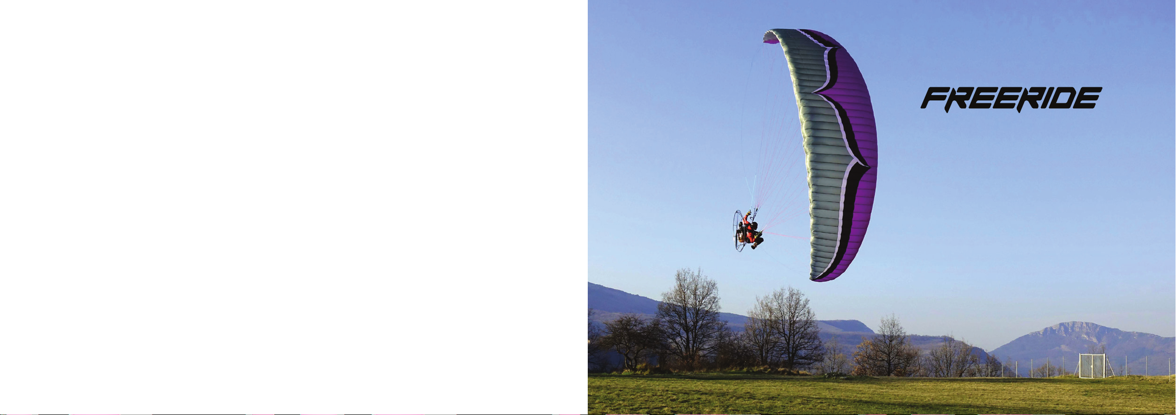
The Freeride is an exciting new concept in advanced PPG wing design. Replacing the Slalom,
the Freeride sits between the Viper 4 and Speedster 2 within the Ozone range. It combines the
speed, precision and efciency of the Viper 4; the handling, agility and pure fun of the Slalom
along with the dependable solidity, comfort and ease of use of the Speedster 2. The Freeride
is a versatile tool for advanced PPG pilots looking for a wing with more dynamic characteristics
than the Speedster 2 whilst being less demanding and more accessible than the Viper 4.
We’ve taken the latest technologies and best features from the Viper 4, Slalom and Speedster
2 to create one of the fastest, most stable PPG wing we have ever produced. The planform and
arc are based on the Viper 4 but with a lower aspect ratio for a more compact and forgiving
feel. The OZRP remains unchanged, featuring Shark nose openings and the highest levels of
CM+ (reex) within the Ozone range. A pure 4 line rigging design and a new internal structure
have been employed to carefully control the angle of attack and increase the chord wise
cohesion of the sail whilst accelerated. The overall effect is an increase in the internal pressure
throughout the speed range for a more forgiving behaviour in turbulence, greater resistance
to spin at higher angles of attack and high levels of inherent stability at lower angles of attack.
The efciency of the sail has been optimised with miniribs, 3D shaping, and plastic rods for a
clean, wrinkle free leading edge.
The risers featuring the OZONE PK system and the option to install either the 2D or “Mateos”
style Slalom Steering Systems.
Although primarily designed for competitive slalom ying, the Freeride is also ideal for classic
competitions, carving aggressive freestyle lines as well as efcient XC ying. The freeride is
designed for experienced PPG pilots looking for a fun, efcient, high performance wing that
can do it all.
RISERS
The risers feature long range trimmers; strong brake handle magnets; B pulleys; Ozone PK
system; 2D steering system with multiple pulley settings; an additional pulley at the main
hang piont loop for the Alex Mateos slalom steering system and coloured A risers for easy
identication.
The slow trim setting, with the trimmers pulled fully is the recommended speed for thermalling,
ridge soaring and maximising the glide angle in calm air. Brake pressure is at its lightest and
handling at its best. If a collapse occurs the wing should be returned to this setting to aid the
fast recovery of collapses..
The trimmers are marked with a line of stitching, this is the recommended setting for ination,
take off, climb out and normal powered ight. This setting is especially useful in light winds
and/or at high altitudes to aid the ination. This is also the best setting for dynamic fun-ying
and slalom-ying offering a good compromise between top speed and tightness of the turn.
The white line setting is also the standard recommended speed for normal ight, to further
increase cruise speed you can use the accelerator system, release the trimmers further, or do
both. Using the accelerator system has exactly the same effect as releasing the trimmers - it
is possible to y with the trimmers in the fully slow position whilst using the full range of the
accelerator system.
With the trimmers fully released it is still possible to use the brakes for directional control
without adversely affecting the stability of the prole too much. However, if you choose to
y faster than this by applying the speed bar, you MUST use the tip steering system to for
directional control, otherwise you risk collapse.
In turbulent air the reex prole is very stable. It will resist reasonable levels of turbulence
with a high resistance to collapse without active pilot input. The faster the wing is own the
more inherent stability there is, as the reex has a greater effect. In mild turbulence it may
be best to not attempt to y the wing actively and let the prole absorb the turbulence itself,
indeed application of the brakes whilst accelerated will reduce the inherent stability of the
prole. However in very strong turbulence Ozone recommends to return the trimmers to the
fully slow position and y the glider actively. This way, you will be in the best position to react
correctly should a collapse occur.
EN
Trimmers
NOTE:
In the slow, neutral
trim setting the risers
are NOT of equal
lengths
IMPORTANT
In thermic or turbulent
air pull the trimmers
to the slow position or
at least to the white
stitch line or accept a
higher risk of collapse
and more dynamic
behaviour.
04
05
Page 6

Accelerator System
The riser’s accelerator system now includes pulleys on the B risers to reduce friction for a
lighter, smoother action. This lighter pressure allows for easier, more comfortable high speed
cruising.
Using the speed system has exactly the same effect as releasing the trimmers. Either can
be used in any combination to accelerate the wing, but be careful, fully accelerated with
trimmers released is very fast and should only be used in calm conditions.
The PK (Paap Kolar) System
The risers feature a PK system which links the front and rear risers to combine the effect of
the accelerator and the trimmers. The advantage of the PK system is that it achieves greater
speeds but with the same accelerator travel essential for competitive slalom ying where it is
not efcient to keep releasing or pulling the trimmers along the course. When accelerating use
a gentle action on the speed bar otherwise, due to the directness of the system it is possible
to create a signicant pitch movement. The brakes MUST NOT be touched whilst ying fast,
instead use the TST for directional control.
The Ozone PK system is permanently built into the risers. The speed bar can be applied
irrespective of the trimmer setting, unlike some other wings, it does not lock the trimmers in
the fully slow position but allows the trimmers to be set as desired. Top speed is reached with
the trimmers released and the speed system fully activated. Whilst pushing the speed bar,
only use the tip steering lines for directional control. Never use the brakes.
IMPORTANT
When accelerated
directional control
should be maintained
with the Tip Steering
System.
Do NOT use the brakes.
IMPORTANT
Using the accelerator
decreases the angle of
attack and can make
the gliders recovery
from a collapse more
aggressive, therefore
using the accelerator
near the ground or in
turbulence should be
avoided.
Brake Lines
The brake line lengths have been set carefully during testing. We feel it is better to have
slightly long brake lines and to y with a wrap when necessary.
• Ensure both main brake lines are of equal length.
• If a brake handle has been removed, check that its line is still routed through the pulley
when it is replaced.
• When the brake handles are released in ight, the brake lines should be slack. There
must be a substantial “bow” in them to guarantee no deformation of the trailing edge.
• There must be a minimum of 10cm of free play before the brakes begin to deform the
trailing edge. This prevents the trailing edge from being deformed when using the speed
system or when controlling the wing with the TST.
Adjustable Brake Pulley Position
The height of the brake line pulley can be chosen according to pilot preference to suite the
power unit’s hang points height and tip steering system. The highest setting (as set by the
factory) is for low hang point motors and for use with the AM steering system, whilst the
middle and lower settings are for units with higher hang points and for a more effective 2D
steering system.
To adjust the pulley height, rst remove the pulleys from the risers and re-attach them at the
desired position. Undo the Velcro magnet attachments for the brake handles and re-attach
them a few cms below the new pulley position.
EN
IMPORTANT
In the unlikely
event of a brake line
snapping in ight, or
a handle becoming
detached, the glider
can be own by gently
pulling the rear risers
(D-risers), or the TST
for directional control.
IMPORTANT
If you adjust the
brake pulley height,
you MUST re lengthen
the brake lines
accordingly.
06
The behaviour during collapse whilst using the PK risers could be more dynamic and the reination could be slower than usual. Use active ying to control direction and pump out the
deation if necessary.
Pro-version risers are also available as an optional extra offering more direct acceleration.
Please contact Ozone if you are interested.
If you alter the pulley position, you must also re-lengthen the brake lines and TST line
accordingly. Measure the distance of the new pulley position from the factory setting and
move the brake handle position by the same amount using the black mark on KRL1 as the
reference.
07
Page 7
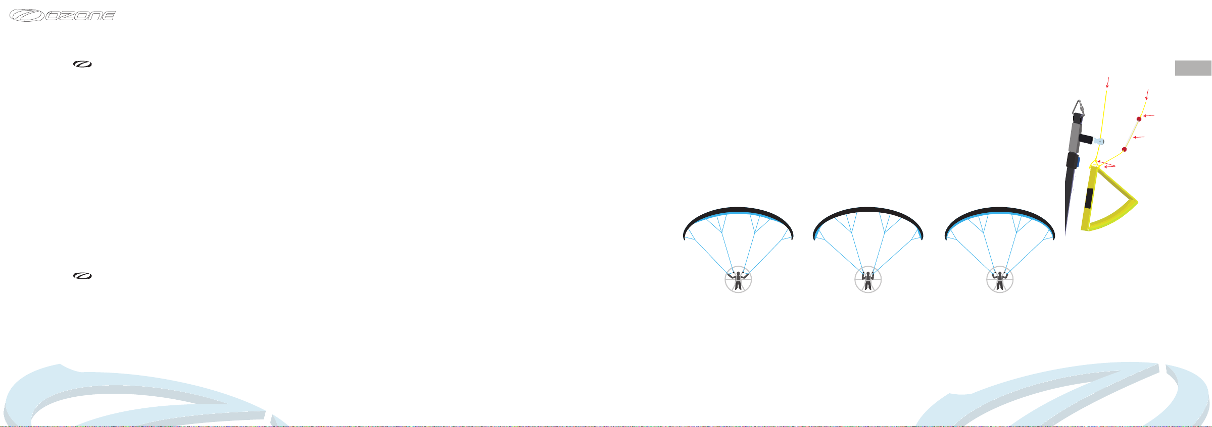
Tip Steering System
The new Tip Steering System uses ergonomic handles to help better control the wing during
high speed ight. The tube-ball handles are attached to the brake handles so they are easily
accessible in ight. When pulled, the TST effects only the very tips of the wing, giving high
levels of precision and comfort for high speed cruising or accurate low level carving, without
compromising stability or the need to use the brakes.
Whilst using the TST, it is not necessary to use large control movements to effect a turn. Be
progressive and gentle at rst until you are familiar with the handling characteristics.
For directional control whilst ying with the speed bar only use the tip steering, DO NOT use
the brakes alone. Application of brake when the wing is at a low angle of attack has a negative
effect on the reex prole: causing loss of precision, adverse roll, and reduced collapse
resistance. In accelerated ight the tip steering system can be used for both directional
control - to keep a straight heading and for effecting nice smooth turns. It becomes more
precise the faster you y.
IMPORTANT
For take off and
landing use only the
brakes. In turbulent
air use the brakes for
directional, pitch and
pressure control.
DO NOT use the TST
The factory setting has been carefully chosen to give a good compromise between maximum
comfort and ease of use for low hang point power units. It can be further adjusted according
to your personal preference, ying style and power unit hang point heights by setting the
differences in length between the brake lines and the TST lines. Shortening the TST lines will
make the 2D system more effective, as will using a lower pulley setting. If you change the
position of the pulley, you must also re lengthen the brake and TST lines. The length of the
brake lines must be adjusted so that they do not engage the trailing edge when accelerated
at maximum speed (open trimmers and full speed bar). After any modication check the set
up on the ground before ying.
The 2D steering system is most effective when using the lowest brake pulley position. It is
important to only pull the TST lines whilst accelerated and not the brakes at the same time,
otherwise you increase the chances of a collapse.
Brake Line
Bowline Knots
EN
TST Line
Figure
8 Knot
Tube Ball
08
When using the tip steering, it is advised to keep the brake handles in the hand or around
the wrists in case of an engine failure or sudden collapse. It is therefore necessary to ensure
that the brake lines are adjusted in such a way that they are not activated when using the tip
steering - make sure the brake and TST lines are set correctly.
2D Steering System
The 2D steering system combines the brake lines and the TST connected via the brake handle.
This system allows you full control of the trailing edge, allowing you to pull only the tip line
(TST), only the center of the trailing edge or both together. Pulling the handle in a downwards
direction and away from your body engages the center of the trailing edge (Scheme 1) whilst
pulling the hand close towards your body will engage rst the wing tips before the rest of the
trailing edge (Scheme 2).
Scheme 1
Push the brake handles
outwards to engage the
brake lines only
Scheme 2
Pull the brake handles
inwards, towards your
body to engage the TST
lines
Scheme 3
Pulling straight down
engages both the brakes
and TST lines
09
Page 8
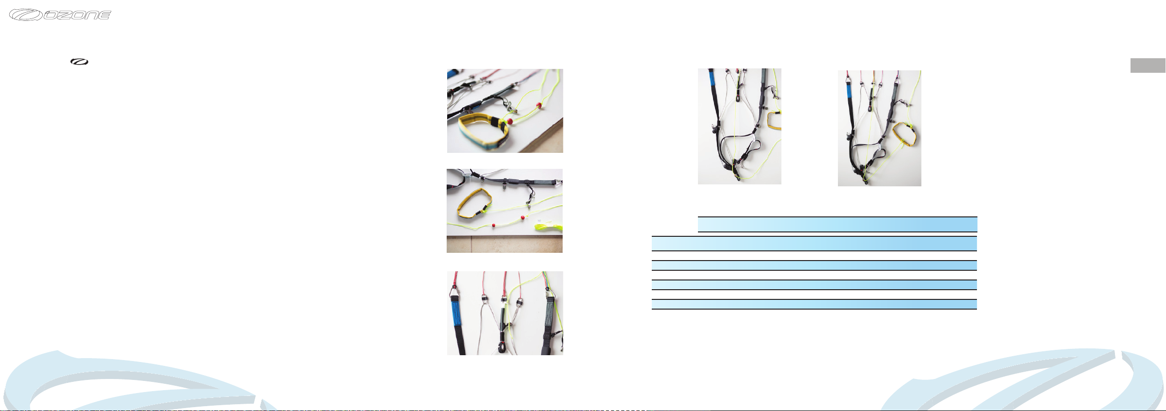
Slalom Steering System (AM)
Additional pulleys and lines are supplied to install the advanced slalom steering system
developed by Alex Mateos. Suitable for competition slalom pilots, the AM system is alternative
to the 2D system and is a safe and effective way of controlling direction whilst accelerating
along the course. The AM steering system will require a certain amount of time to learn
the correct movements, but once mastered allows the pilot full directional control whilst
accelerated without the risk of inadvertently activating the brakes.
To use the AM system, the pilot moves their hand in a diagonal upwards motion which causes the
brake line to be lengthened rather than shortened as it is when using the 2D steering system,
therefore there is no possibility of accidentally engaging the brake lines whilst accelerated. For
a detailed description and explanation of the system please look at the instructional video on
the Ozone Paragliders Vimeo channel here: https://vimeo.com/164598468
Fig 1
Fig 2
Fig 4
Fig 5
EN
IMPORTANT
The AM system is
most effective with
the upper brake pulley
position.
10
To install the AM steering system:
• The brake lines should be routed through the upper long pulley as supplied in the standard
factory setting (Fig 1). Do not use the middle or lower pulley.
• Disconnect TST (Ktrl) line from the brake handle (Fig 2).
• Remove the current TST line (Ktrl) and replace it with the longer TST line included with the
wing.
• Pass the new TST (Ktrl) line through the ring located near the B maillon (Fig 3).
• Pass the TST line through the pulley at the bottom of the risers near the main hang loop
(Fig 4).
• Tie the TST line into the brake handle (Fig 5).
Fig 3
Set initial length of the lines as following:
Factory Settings AM Steering System 2D Low Pulley Setting
Size Brake line TSL (Ktrl) Brake line TSL (Ktrl) Brake line TSL (Ktrl)
15
16
17
19
21
23
These initial settings have been dened by Alex according to his paramotor unit / personal
preference and arm lengths. It may not be the most suitable lengths for you. From this initial
setting adjust the lengths of the brake lines and TST according to your requirements.
124 106.5 130 171.5 140.5 106.5
127 106 133 177 146 106
130 106 136 177 150 106
136.5 106 140 177 160.5 106
142 105 148 177 167 105
149.5 105 156 177 173.5 105
11
Page 9
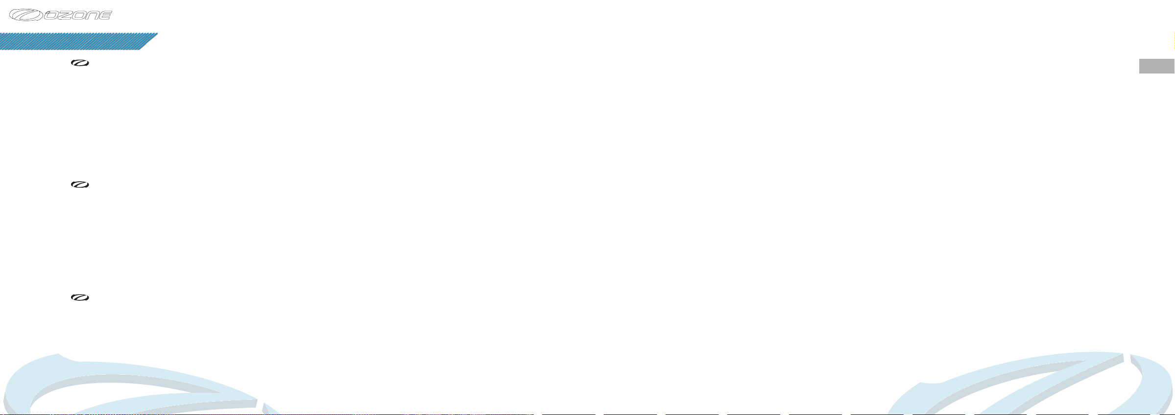
PREPARATION
Accelerator System
To set up the accelerator on the ground, ask a friend to pull your risers into their in-ight
position while you sit in your harness. Now adjust the length of the line so that the main bar
sits just beneath your seat. You should now be able to hook your heel in to the secondary
(lower) loop of the accelerator.
The accelerator must be slack enough to ensure that the front risers are not pulled down in
normal ight, but not so long that it is impossible to use the full range of the speed system.
Ensure that the speed bar is secured in place before take off to avoid fouling the prop. Once
set up, test the full range of the speed system in calm ying conditions: ensure that both
risers are pulled evenly during operation. Fine-tuning can be completed when you are back
on the ground.
Harness and Motor
It will be in your harness that you will enjoy ying. Therefore, we recommend you spend the
time on the ground to adjust your harness’ different settings. Hang from a solid beam and
double check that you are comfortable and that you can reach the brake handles, tip steering
handles and that you can achieve the full range of speed bar travel before ying.
The Freeride is suitable for all types of motor. There are many different motor units available
and it is vitally important that you choose one that is suitable for your needs, weight and skill
level. Due to the high performance prole of the Freeride, a unit with a less powerful motor
and low movable hang points may be advisable. Always seek assistance and advice from your
instructor or experienced pilots before choosing equipment for yourself.
Wing
To familiarise yourself with the glider it is a good idea to perform practice inations and ground
handling with and without the motor. As with all new equipment; only y in conditions that
you would normally y in and on a familiar site for the rst time. Fly the wing progressively.
Lay out the wing downwind of your motor on its top surface in a pronounced arc, with the
IMPORTANT
When accelerated
directional control
should be maintained
with the TST system.
Do NOT use the brakes.
IMPORTANT
Never apply the brakes
whilst using the speed
system - it makes the
wing more prone to
collapse.
centre of the wing higher than the tips. Lay out the lines one side at a time. Hold up the risers
and starting with the brake lines, pull all lines clear. Repeat with the D, C, B and A lines, laying
the checked lines on top of the previous set, and making sure no lines are tangled, knotted or
snagged. Mirror the process on the other side.
Take-off checklist:
1. Check reserve parachute - pin in and handle secure
2. Helmet on and fastened
3. All harness buckles closed - check leg-loops again
4. Carabiners and maillons tight
5. Holding the A’s, your brake handles and throttle
6. Leading edge open
7. Aligned directly into wind
8. Engine warm and able to deliver full power
9. Trim set correctly
10.Prop clear of lines
11.Airspace and visibility clear
EN
IMPORTANT
Always lay out your
glider downwind of the
motor, never leave the
motor downwind of
the wing or connected
to the motor if
unattended.
12
13
Page 10
BASIC FLIGHT TECHNIQUES
Launching
Your Freeride will launch with either the forward or reverse launch techniques. To improve the
ination characteristics, it is advised to adjust the trimmers to the white line.
When taking off under power, make sure there is enough clear space upwind of you to launch
and climb out safely, avoiding trees, power lines and any other obstacles that may affect you
should you have a power failure. Always y with a safety margin so that power failures do not
leave you compromised. You should always be able to glide power off to a suitable landing
place.
Once clipped in, and you have gone through the take-off check list (above), stand central to
the wing to ensure an even and progressive ination. Whilst inating your wing, you should
hold both of the A risers on each side.
Run in an upright position so that the motor is generating forward thrust, do not lean too far
forward otherwise the power of the motor will attempt to push you into the ground! When you
have enough airspeed a gentle application of brake will help you lift off. Do not stop running
until your feet have left the ground and you are sure of a safe climb out.
Forward Launch - Nil to Light winds
When the wind is favourable, move forward positively: your lines should become tight within
one or two steps. The Freeride will immediately start to inate. You should maintain a constant
pressure on the risers until the wing is overhead.
Do not pull down or push the risers forward excessively, or the leading edge will deform and
possibly collapse making taking-off more difcult and potentially dangerous.
Move smoothly throughout the entire launch, there is no need to rush or snatch at it. You
should have plenty of time to look up and check your canopy before committing yourself.
Once you are happy that the Freeride is inated correctly, progressively apply full power and
accelerate smoothly for the launch.
IMPORTANT
Never take off with
a glider that is not
fully inated or if you
are not in control of
the pitch/roll of your
wing.
During a forward launch we advise to NOT use the power launch technique. During the
ination the power should be progressively applied once the wing is half way up. Applying the
power too early may inhibit the ination characteristics of the center part of the wing, causing
the wing tips to come up faster.
Reverse Launch -Light to Strong Winds
Lay out your Freeride as you would for the forward launch. However, this time face the
wing, and attach the risers in the correct manor (half a turn in each riser, and crossed in the
direction you want to turn). Now you can pull up the Freeride by its A-risers. Once the wing
is overhead, brake it gently, turn and launch.
In stronger winds, be prepared to take a few steps towards the glider as it inates. This will
take some of the energy out of the glider and it will be less likely to over-y you. Once stable
and above your head apply progressive power and accelerate smoothly for a controlled take
off.
Practice ground handling and launching as much as possible! It is great fun, and will give you
a much better feel for your Freerides ight characteristics. It will also improve your overall
enjoyment of ying by making your launches easier and safer.
The Climb Out
Once in the air you should continue ying into wind whilst gaining height. By setting the
trimmers to the rst white line position you will achieve the best climb rate. Do not attempt
to climb too steeply or too quickly by using the brakes or slow trim. The wing already has a
high angle of attitude, coupled with a higher AoA (if you use the brakes) plus the engine’s
full thrust acting on the pilot, this could contribute to make the glider more prone to stall.
Furthermore, in the event of an engine failure the resulting backward pendulum motion of
the pilot and the forward dive of the wing may bring you back to the ground very hard. Do
not initiate turns until you have sufcient height and airspeed. Avoid low turns downwind with
insufcient airspeed.
IMPORTANT
EN
The trimmers should
be set to the white
line position for better
ination behaviour
during take-off. This is
especially important in
light winds and/or at
high altitudes.
14
15
Page 11
The Freeride is well damped in roll but under certain circumstances it is possible for the
pilot to induce oscillations. Pilot induced oscillations can be caused by a number of different
reasons, or combinations thereof. Engine/propeller torque, pilot weight shift and/or brake
inputs, width of hangpoints and frame geometry to name a few. To stop unwanted oscillations
it is best to rst reduce the power and then ensure to remain static within the harness and
not make inputs with the brakes. Once settled you can once again apply full power. Under full
power the torque effect will attempt to gently turn the wing, using weight shift or adjusting
the trims asymmetrically is the best method to correct this.
The handling characteristic of the Freeride is truly amazing. We have worked hard on tuning
the wing so that it turns tightly but also efciently, as the ability to climb in a turn is very
important for powered and free ight, making the climb out fun and thermalling easy.
Normal Flight
Once at a safe height you can release the trimmers for a faster cruise speed. If your motor
has enough power, the Freeride will achieve very good straight line speeds whilst maintaining
level ight with trims fully released and full speed bar applied. Be cautious when ying at high
speeds, only do so in calm conditions.
For better penetration in headwinds and improved glide performance in sinking air, crosswinds
or headwinds, you should y faster than trim speed by using the accelerator system, or the
trimmers. For maximum efciency whilst ying downwind, release the speed bar and return
the trimmers to the slow position.
By pulling the trimmers to the slow position and applying a small amount of brake, the
Freeride will achieve its best minimum-sink rate; this is the speed to use for thermalling and
ridge soaring whilst free ying.
Turning
To familiarize yourself with the Freeride your rst turns should be gradual and progressive.
To make efcient and coordinated turns with the Freeride rst look in the direction you want
to go and check that the airspace is clear. Your rst input for directional change should be
weight-shift, followed by the smooth application of the brake until the desired bank angle is
achieved. To regulate the speed and radius of the turn, coordinate your weight shift and use
the outer brake.
Active Flying
In turbulent air the Shark nose Ozone reex prole (OZRP) is very stable. It will resist
reasonable levels of turbulence without pilot input. The faster the wing is own the more
inherent stability there is as the reex has a greater effect. Using the speed system has
exactly the same effect as releasing the trimmers so it is safe and possible to y with the
trimmers in the slow position whilst using the full range of the speed system.
In mild turbulence it may be best to not attempt to y the wing actively and let the prole
absorb the turbulence itself, indeed small applications of the brakes can reduce the inherent
stability of the prole. However in very strong turbulence Ozone recommends to return the
trimmers to the slow neutral position and y the glider actively. This way, you will be in the
best position to react correctly should an incident occur.
The key elements of effective active ying are pitch control and pressure control: In very
turbulent air, if the glider pitches hard in front of you, use the brakes to slow it down. Equally,
if the glider drops behind you, release the brakes to allow it to speed up.
Avoid ying with continuous amounts of brake in rough air as you could inadvertently stall the
wing. Always consider your airspeed.
The OZRP is a very stable prole and can accept large amounts of turbulence before collapsing.
If the turbulence is not too severe it may be best to not y actively and let the prole absorb
the turbulence itself. However, no pilot and no glider are immune to collapses. In severe
turbulence active ying will virtually eliminate any tendency to collapse. When the conditions
are very turbulent, be more active and anticipate the movements of your wing. Always be
aware of your altitude and do not over-react.
EN
IMPORTANT
Never initiate a turn at
minimum speed (i.e.
with full brakes on) as
you could risk entering
a spin.
IMPORTANT
Always keep hold of
your brakes. Do not y
in turbulent conditions
16
17
Page 12
ADVANCED FLIGHT TECHNIQUES
Landing
The Freeride shows no unusual landing characteristics. We recommend the trimmers be
returned to the normal slow position for landings. You can land un-powered or powered, here
are some tips:
• Always set up your landing early, give yourself plenty of options and a safe margin for
error and make sure you are heading INTO wind.
• Once below 30 metres avoid turning tightly as the glider will have to dive to accelerate
back to normal ight.
• Allow the glider to y with speed for your nal descent until you are around 1 metre
above the ground. Apply the brakes slowly and progressively to slow the glider down until
the glider stalls and you are able to step onto the ground.
• It is safest to perform un-powered landings as this reduces the likelihood of propeller
damage caused by either falling over or allowing the lines to foul the prop. Turn off the
engine at around 30m and glide in like a normal paraglider.
• Powered landings offer the chance to power up and continue with the ight if you misjudge
your nal approach, but can be more expensive if you get it wrong!
• Choose the appropriate approach style in function of the landing area and the conditions.
• In light winds you need a strong, long and progressive are to bleed off all your excess
ground speed. In strong winds your forward speed is already low so you are aring
only to soften the landing. A strong are may result in the glider climbing upwards and
backwards quickly, leaving you in a vulnerable position.
• In strong winds you need to turn towards the glider the second your feet touch the
ground. Once facing the wing pull smoothly and symmetrically down on the brakes to
stall the wing. If the glider pulls you, run toward it.
• If the wind is very strong, and you feel you might be dragged, stall the glider with the C
risers. This stalls the Freeride in a very quick and controllable way and will drag you less
than if you use the brakes.
Rapid Descent Techniques
Ozone would like to remind you that these manoeuvres should be learnt under the supervision
of a qualied instructor and always used with caution. Never forget that a thorough analysis
of the conditions before launch will help avoid the need to use these techniques.
Big Ears
Folding in the wing tips of the Freeride increases its sink rate. This is useful for staying out of
cloud or descending quickly. To pull big ears on the Freeride take hold of the outermost A-line
(Baby A) on each side whilst keeping the brake handles in your hand. Pull down the baby A
risers until the tips of the wing fold under.
Do not use the brakes other than for re-ination. For directional control while using the Big
Ears, you should use weight shift steering. To reopen your big ears, release both baby As at
the same time. To help re-ination, brake gently one side at a time until tips regain pressure.
Avoid deep symmetric applications of the brake as this could induce parachutal or full stalls.
Big Ears and Accelerator
Once the big ears are in you can further increase the sink rate by pushing on the accelerator
bar. Never attempt to induce Big Ears with the speed bar already engaged, always make the
Big ears before accelerating the wing otherwise you risk provoking a major asymmetric or
symmetric deation.
Big Ears and Spiral Dive
Whilst it is possible to enter a spiral dive whilst holding in Big Ears, the high forces applied
to the lower lines could exceed the breaking strain of the lines leading to equipment failure!
B-Line Stall
B-stall is for fast descents in emergency situations only. B-stall is performed by symmetrically
pulling down on the B-risers. The load applied on the B lines during this manoeuvre is not very
good for your wing; only use it in emergency situations.
EN
IMPORTANT
Induce Big ears one
side at a time
NEVER induce Big
Ears in accelerated
ight, this can lead
to a major deation.
Always pull the Big
Ears rst and then
apply the speed bar.
DO NOT perform spiral
dives with Big Ears
engaged.
18
19
Page 13
To initiate the B-stall place your ngers between the lines above the maillons on the B risers.
Do not release the brake handles. As you pull the B-lines down the airow over the wing
is broken and the glider loses its forward speed but remains open and you will descend at
around 6 m/s.
If you pull too much B-line the glider may horseshoe and move around a lot.
To exit the B-stall the B-risers should be released symmetrically and in one smooth, fast
progressive motion. The glider will resume normal forward ight without further input. Check
you have forward ight again before using the brakes. Do not release the B lines slowly, this
may lead to a parachutal stall.
Spiral Dives
If you turn your Freeride in a series of tightening 360’s it will enter a spiral dive. This will
result in rapid height loss. It is likely that the wing has neutral, possibly unstable tendencies
during the spiral dive which will require active piloting to return to normal ight.
Safe descent rates are possible but high speeds and high G-forces can build quickly leading
to disorientation. Excessive G forces can lead to loss of consciousness. High descent rates
increase the likelihood of the wing remaining neutral, possibly unstable in spiral.
Ozone strongly recommends to not perform spiral dives with high descent rates.
To initiate a spiral dive, look and lean in to the direction you want to turn and then smoothly
apply the inside brake. The Freeride will rst turn almost 360 degrees before it drops into the
spiral (depending on the input). Once in the spiral you should apply a little outside brake to
keep the outer wing tip pressured and inated.
To exit the spiral dive, weight shift away from the direction of rotation and smoothly release
the inside brake. As the Freeride decelerates allow it to continue to turn until enough energy
is lost for it to return to level ight without an excessive climb and surge.
IMPORTANT
Always be prepared
to pilot the wing out
of a spiral dive. Use
opposite weight shift
and apply enough
outside brake to
stop the wing from
spiralling.
Always be prepared to pilot the wing out of a spiral dive. In case of neutrality/instability use
opposite weight shift and smoothly apply enough outside brake to provoke the glider to exit
the spiral.
IMPORTANT: The Freeride is a small and dynamic wing, the spiral entrance is
dynamic and very high sink rates can be achieved. Spiral dives are dangerous and
put unnecessary strain on the glider, they cause disorientation and need time and
height to recover. Do not perform this manoeuvre near to the ground.
EN
20
21
Page 14
INCIDENTS IN FLIGHT
Deflations
Due to the exible form of a paraglider, turbulence may cause a portion of the wing suddenly
to collapse. This can be anything from a small 30% (asymmetric) collapse to a complete
(symmetric) collapse. If you have a collapse, the rst thing to do is to control your direction.
You should y away from the ground or obstacles and other pilots, or at least not to y into
them... Asymmetric collapses can be controlled by weight shifting away from the collapse and
applying a small amount of brake to control your direction. This act will most of the time be
enough for a full recovery of the wing.
Once a glider is deated it is effectively a smaller wing, so the wing loading and stall speed
are higher. This means the glider will spin or stall with less brake input than normal. In your
efforts to stop the glider turning towards the collapsed side of the wing you must be very
careful not to stall the side of the wing that is still ying. If you are unable to stop the glider
turning without exceeding the stall point then allow the glider to turn whilst you reinate the
collapse.
If you have a deation which does not spontaneously reinate, make a long smooth
progressive pump on the deated side. This pumping action should take about 2 seconds per
pump. Pumping too short and fast will not reinate the wing and pumping too slow might take
the glider close to, or beyond, the stall point.
Symmetrical collapses normally reinate without pilot input, however 15 to 20cm of brake
applied symmetrically will speed the process.
If your wing collapses in accelerated ight, immediately release the accelerator and pull the
trimmers to the slow position then attempt to reinate the canopy.
Cravats
If the tip of your wing gets stuck in the lines, this is called a ‘cravat’. This can make your glider
go into a spiral, which is difcult to control. The rst solution to get out of this situation is to
stabilise the glider into normal ight, i.e get control of your direction and then pull down the
stabilo line until the wing tip frees itself. You must be careful with any brake inputs or you
may stall the opposite wing. You can also use strong deep pumps on the brake to the cravated
side, when doing so it is important to lean away from the cravat otherwise you risk spinning
or deepening the spiral. The aim is to empty the air out of the wing tip, but without spinning.
Correctly done, this action will clear the cravat.
If it is a very large cravat and the above options have not worked then a full stall is another
option. This should not be attempted unless you have been taught how to do it and can only
be done with a large amount of altitude. Remember if the rotation is accelerating and you are
unable to control it, you should throw your reserve parachute whilst you still have enough
altitude.
Deep Stall / Parachutal Stall
It is possible for gliders to enter a state of parachutal stall. This can be caused by several
situations including; a very slow release from a B-line stall; ying the glider when wet; or
after a front/symmetric deation. The glider often looks as though it has recovered properly
but carries on descending vertically without full forward motion. This situation is called ‘deep
stall’ or ‘parachutal stall’. Should it happen, your rst reaction should be to fully raise both
brakes, this action alone normally allows the glider to return to normal ight. If nothing
happens after a few seconds, apply the speed bar or release the trimmers to regain normal
ight. Ensure the glider has returned to normal ight (check your airspeed) before using the
brakes again.
Never y in rain or with a wet wing, this will signicantly increase the likelihood of parachutal
stall. If you are accidently caught-out in a rain shower, land immediately. DO NOT use big
ears as a descent technique; big ears with a wet wing will further increase the chances of a
parachutal stall occurring. Instead, lose height with gentle 360’s and make sure to consider
your air speed during nal approach, use a small amount of speed bar if necessary.
IMPORTANT
A bad preparation
on launch, aerobatic
ying, ying a wing of
too high a level or in
conditions too strong
for your ability, are
the main causes of
cravats.
IMPORTANT
Only a few cms of
input from your
brakes can maintain
your wing in the stall.
Always release your
wraps if you have
taken them!
IMPORTANT
Never y in the rain or
with a wet glider
EN
22
23
Page 15
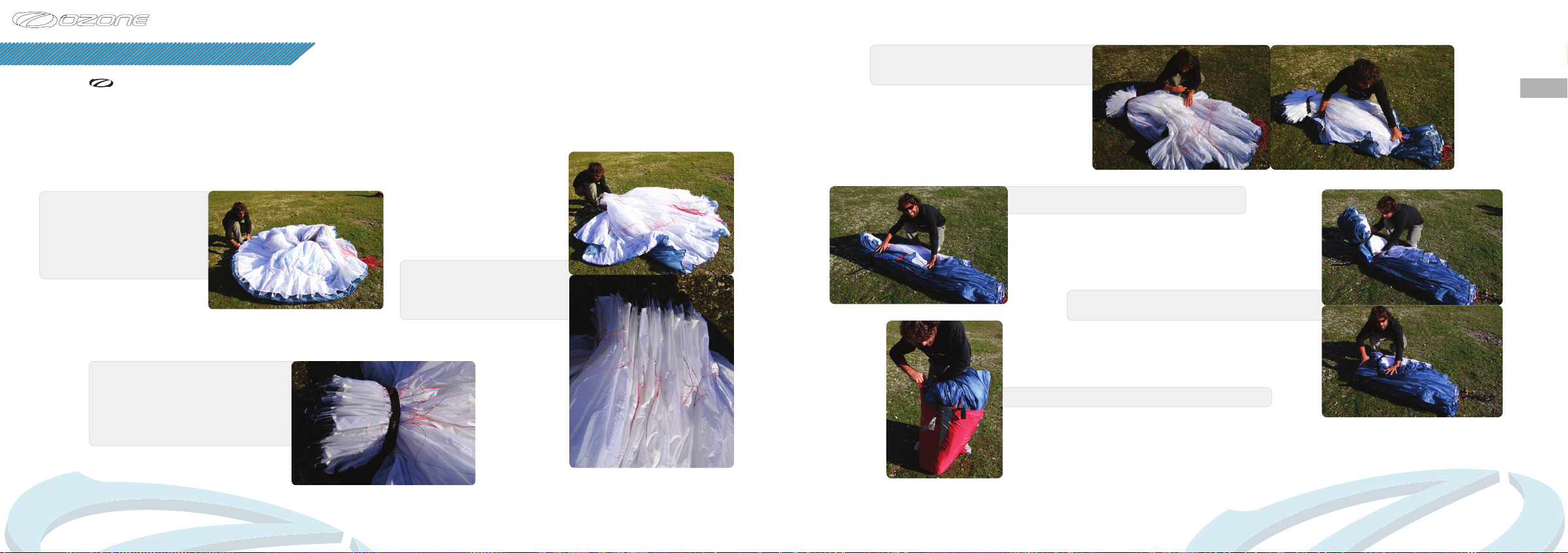
CARE AND MAINTENANCE
Packing
To prolong the life of your wing and to keep the plastic reinforcements in the best possible condition it is very important to
pack the wing carefully.
Ozone recommends to use the concertina packing method exactly as shown so that all of the cells rest alongside each
other and the plastic reinforcements are not unnecessarily bent. Using an Ozone Saucisse or Saucisse light pack will help
preserve the life of the wing and aid with the speed and ease of packing.
Step 4. Group together the middle/trailing
edge of the wing by sorting the folds near
the B, C and D tabs.
If using a Saucisse pack go to Step 8.
EN
Step 1. Lay mushroomed wing
on the ground. It is best to start
from the mushroomed position
as this reduces the dragging
of the leading edge across the
ground.
Step 3. Lay wing on its side and Strap
LE...Note the glider is NOT folded
in half; it is folded with a complete
concertina from tip to tip. It is really
important to not stress the middle cell or
bend the plastic too tightly.
24
Step 2. Group LE reinforcements
with the A tabs aligned, make
sure the plastic reinforcements
lay side by side.
Step 5. Once the LE and rear of the wing have
been sorted, turn the whole wing on its side.
Step 6. Fold the wing with 3 or 4 folds whilst being
careful to not crush the LE.
Step 7. Now place the folded wing into the stuff sack.
25
Page 16
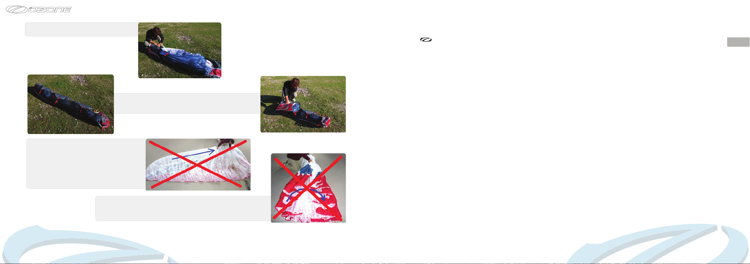
Step 8. If using the Saucisse Pack, carefully
zip it up without trapping any material.
Step 9. Turn the Saucisse on its side and make the rst
fold just after the LE reinforcements. Do not fold the plastic
reinforcements, use 3 or 4 folds around the LE.
IMPORTANT: Do NOT lay the wing
at on the ground before packing the
glider, this will cause abrasion damage
to the top surface as you pull the glider
towards the middle. ALWAYS pack from
a mushroom or lift the wing off the
ground when gathering the wing and
grouping the leading edge.
IMPORTANT: Do not fold the glider in the centre, you
will bend the plastics, instead pack the wing with a full
concertina method from tip to tip before packing into the
stuff sac.
Caring Tips
Careless ground handling damages many paragliders. Here are some things to avoid in order
to prolong the life of your aircraft:
• DO NOT drag your wing along the ground to another take-off position - this damages the
sailcloth. Lift it up and carry it.
• DO NOT try to open your wing in strong winds without untangling the lines rst - this puts
unnecessary strain on the lines.
• DO NOT walk on the wing or lines.
• DO NOT repeatedly inate the glider and then allow it to crash back down. Try to keep this
movement as smooth as possible by moving towards the glider as it comes down.
• DO NOT slam your glider down on the ground leading edge rst! This impact puts great
strain on the wing and stitching and can even explode cells.
• FLYING in salty air, in areas with abrasive surfaces (sand, rocks etc.) and ground handling
in strong winds will accelerate the aging process.
• DO NOT y in the rain or expose the wing to moisture.
• DO NOT expose the wing to unnecessary UV. Pack away once you have nished ying. Do
not leave it sitting in the sun.
• If you y with a wrap, you should regularly undo the twisting that appears on the main
brake lines. By twisting the line become shorter and you can end up with a constant tension
on the trailing edge which can affect the launch and handling behaviour.
• Change your main brake lines if they are damaged.
• Be Careful when groundhandling to not saw the brake lines against the risers or main lines.
The abrasion caused by a sawing motion can damage the main lines and lead to premature
ageing of the risers. If you notice any signs of abrasion, especially to the lines, make
sure you get the wing professionally serviced and importantly modify your groundhandling
technique to stop any further damage.
• Your Ozone wing has an opening closed using Velcro on the trailing edge of the tip called
the ‘Butt hole’. This has been designed to easily empty all the things which have been
accumulating in your wing (sand, leaves, rocks, mobile phones etc).
EN
26
27
Page 17
Storage and Transport
Always store all your ying equipment in a dry room, protected from direct heat. Your wing
should be dry before being packed away. Moisture, heat and humidity are the worst elements
for damaging your glider. Storing a damp glider in your car under the sun would be terrible
for example.
If you land in salt water, you must rst rinse it thoroughly with clean fresh water. Dry the wing
completely, preferably out of the sun, in the wind. Never use a hair dryer, etc.
IMPORTANT
Never pack away or
store your glider wet.
If you damage a line:
Any line that is visually damaged MUST be replaced. Use a reputable paragliding service
centre to make the replacement lines. Alternatively you can order them from your local Ozone
dealer or directly from our website http://www.yozone.com/paragliders/en/shop/lines.php
It is important that replacement lines are made from the correct materials and diameters. You
should check lengths against their counterpart on the other side of the wing to make ensure
symmetry. Once the line has been replaced, inate and check the glider before ying.
EN
28
Take care that no insects get packed away with the wing. They may eat the cloth and make
holes in a bid to escape. They can also leave acidic deposits if they die and decompose.
Transport the wing in the supplied bags and keep away from oils, paints, chemicals, detergents
etc.
Cleaning
Any kind of wiping/scratching can damage the coating of the cloth. We recommend to not
clean the wing, but if you do have to, use a soft cloth dampened with a small amount of water
and use gentle movements little by little across the surface.
Wing Repairs
Always let a registered dealer, professional repair centre or the manufacturer carry out any
major or complex repairs, especially those near seam margins.
If you damage the sail:
If the rip is small and in the middle of a panel however you can x it yourself. You’ll nd all the
materials in the repair kit you need. The fabric can be simply mended with the sticky rip stop/
spinnaker tape. When cutting out the patches allow ample overlap of the tear and make sure
both sides are different sizes. Make sure to round off each corner of the patches.
You can nd more information about repairing your wing on the Ozone website, including step
by step instructions with pictures.
IMPORTANT
Never use detergent or
chemical cleaners.
Maintenance Checks
Your wing, like a car, should be technically checked to ensure proper airworthiness. Your
wing should be checked by a qualied professional for the rst time after 24 months, or
after 100 hours. However, if you are a frequent yer (more than 100 hrs per year), then we
recommend, that you get your glider checked annually. The checker should inform you about
the condition of your glider and if some parts will need to be checked or changed before the
next normal service check period.
The sail and the lines do not age in the same way or at the same rate; it is possible that you
may have to change part or all of the lines during the wing’s life. For this reason it is important
to do regular inspections so that you know the exact condition of all of the components of your
glider. We recommend that inspections are carried out by a qualied professional.
You alone are responsible for your ying kit and your safety depends on it. Take care of
your equipment and have it regularly inspected. Changes in ination/groundhandling/ying
behaviour indicates the gliders aging, if you notice any changes you should have the wing
checked before ying again. These are the basic elements of the check up (full details and
permissible gures can be found on our website)
Porosity is measured with a porosity meter, the time taken by a certain volume of air to go
through a certain surface of the cloth. The time in seconds is the result. A measurement is
done in a several places on the top surface along the span of the glider behind the leading
edge.
29
Page 18

LIMITATIONS
The tearing resistance of the cloth - A non-destructive test following the TS-108 standard
which species minimum tear strength for sky diving canopies should be made using a
Bettsometer. (B.M.A.A. Approved Patent No. GB 2270768 Clive Betts Sails)
Strength of the lines - An upper, middle and lower A line, along with a lower B and a lower
C (and lower D if applicable) line should be tested for strength. Each line is tested to breaking
point and the value recorded. The minimum value is 8 G for all lower A+B lines and 6 G for all
lower remaining lines, calculated from the maximum certied ying weight of the glider. The
added minimum strength for the middle lines and for the top lines should be the same. If the
breaking strength is too close to the minimum value calculated, the professional should give
a period after which you will have to test the strength of the lines again.
Lengths of the lines - The overall length (riser lines + mid lines + upper lines) has to be
checked under 5Kgs of tension. The difference between the measured length and the original
length should not exceed +/- 10mm. The changes that could appear are a slight shrink on the
C or Ds and/or a slight stretch on the A, B. The consequences of these changes can include a
slower trim speed, difcult ination etc.
Risers - Visual inspection for signs of wear or abrasion. Differences to manual lengths should
not exceed +/-5mm.
Canopy check - A full visual check should be carried out: All the components of the wing
(stitching, ribs, diagonals, lines, tabs, ...) should be checked for signs of deterioration.
Finally, a test ight to conrm that the wing behaves normally should be carried out by a
professional.
IMPORTANT
Take care of your
glider and make sure
you have it checked
and serviced according
to the schedule.
The Freeride has been designed as a solo high performance paramotoring wing for
competent experienced pilots only. It is not suitable for beginner or intermediate pilots nor
is it intended for training, tandem ights or aerobatic manoeuvres.
Ozone wings are designed and tested to the highest standards, the Freeride has passed
the EN 926.1 load test and has DGAC certication, however it has not undergone any third
party ight certication. All owners and pilots should be aware of the uncertied nature of
the wing before ying for the rst time.
Trike Flying
The Freeride may be used with a light solo trike so long as the maximum recommended
weight range, and the maximum permitted load test results are respected.
Towing
The Freeride may be tow-launched. It is the pilot’s responsibility to use suitable harness
attachments and release mechanisms and to ensure that they are correctly trained on the
equipment and system employed. All tow pilots should be qualied to tow, use a qualied tow
operator with proper, certied equipment, and make sure all towing regulations are observed.
Total Weight in Flight
Each Ozone glider has been designed with a dened weight range. Wing loading has a
signicant effect on the behavior and characteristics of the Freeride. Flying at the maximum
recommended load is only suitable for very experienced pilots who have the necessary skills
to control a dynamic wing with precise control. We advise you to aim for the middle of the
recommended weight range.
EN
IMPORTANT
Heavily loaded the
wing is very dynamic.
Choose the best size
suitable for your
all up weight and
experience.
30
31
Page 19
OZONE QUALITY GUARANTEE
Flying in the Rain
Modern wings are susceptible to rain and moisture, ying with a wet wing can result in the
loss of normal ight.
Due to the efcient, wrinkle-free design of the sail, water tends to bead on the leading
edge causing ow separation. Flow separation will make the wing more prone to entering
inadvertent parachutal stalls, so ying in the rain, or with a wet wing (e.g early morning dew)
should be avoided at all costs.
If you are accidently caught-out in a rain shower, it is best to land immediately. If your wing
becomes wet in the air it is advised to maintain accelerated ight using the speed bar and/
or releasing the trimmers, even during the nal approach. DO NOT use big ears as a descent
technique, big ears increases drag, and with a wet wing this will further increase the chances
of a parachutal stall occurring. Instead, lose height with gentle 360’s and maintain your air
speed at all times. If your wing enters parachutal stall when wet, immediately release the
trimmers and accelerate the wing to regain airspeed.
Modifications
Your Ozone Freeride was designed and trimmed to give the optimum balance of performance,
handling and safety. Any modication voids the certication and will also make the wing more
difcult and dangerous to y. For these reasons, we strongly recommend that you do not
modify your glider in any way.
IMPORTANT
Do not y your wing
when it is wet.
IMPORTANT
Do not modify your
wing in any way.
At Ozone we take the quality of our products very seriously, all our gliders are made to the
highest standards in our own manufacturing facility. Every glider manufactured goes through
a stringent series of quality control procedures and all the components used to build your
glider are traceable. We always welcome customer feedback and are committed to customer
service. Ozone guarantees all of its products against manufacturer’s defects or faults. Ozone
will repair or replace any defective product free of charge. Ozone and its distributors provide
the highest quality service and repair, any damage to products due to wear and tear will be
repaired at a reasonable charge.
If you are unable to contact your dealer then you can contact us directly at info@yozone.com
Summary
Safety is paramount in our sport. To be safe, we must be trained, practised and alert to the
dangers around us. To achieve this we must y as regularly as we can, ground handle as much
as possible and take a continuous interest in the weather. If you are lacking in any of these
areas you will be exposing yourself to more danger than is necessary.
Respect the environment and look after your ying sites.
If you need to dispose the wing, do so in an environmentally responsible manner. Do not
dispose of it with the normal household waste.
Finally, RESPECT the weather, it has more power than you can ever imagine. Understand what
conditions are right for your level of ying and stay within that window.
Happy ying & enjoy your Freeride.
Team Ozone
EN
32
33
Page 20
MATERIALS
Freeride
Rigging Diagram
All Ozone gliders are made from the highest quality materials available.
Cloth
Upper Surface
Dominico DOKDO 30D MF
Lower Surface
Dominico DOKDO 20D MF
Internal Ribs
Dominico DOKDO 30D FM
Leading Edge Reinforcement
2.5/1.8mm Plastic pipe
Main Line Set Brake Lines
Riser Lines Main brake/TST Lines
Edelrid 6843 - 160/200kg Liros - 10-200-040/DSL -70/140kg
Middle Lines Middle brake lines
Edelrid 8000U - 50/70/90/130kg Edelrid 8000U - 50/70kg
Upper Lines Upper brake lines
Edelrid 8000U - 50/70/90kg Edelrid 8000U - 50kg
Risers and Hardware
Shackles
Maillon Rapide - Pegeut
Riser webbing
20mm zero stretch polyester webbing
Pulleys
Ronstan ball bearing
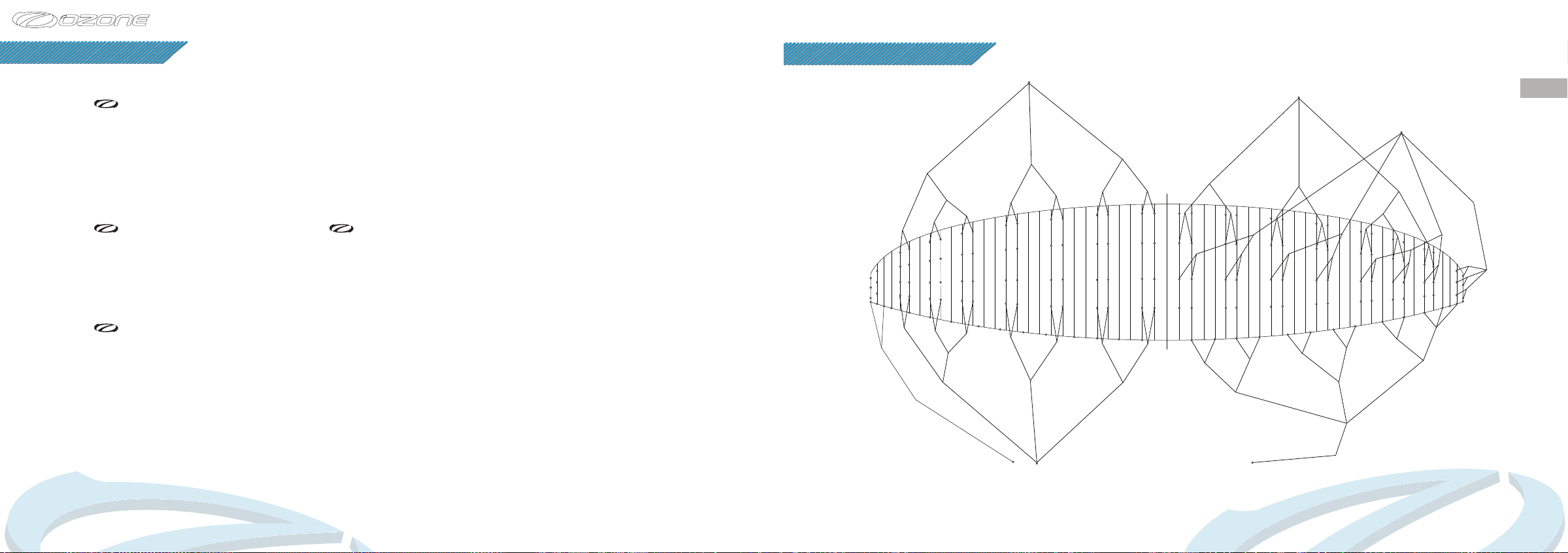
LINE DIAGRAM
AM 5
AM 6
AMU 2
A 10
A 11
A 12
A 13
A 14
D 14
D 13
D 12
D 11
D 10
KT 1
KT 2
DMU 2
DM 6
KTRU
DM 5
KTRL
AMU 1
DMU 1
Individual and linked line lengths can be found online.
A Riser
B Riser
AR 3
AM 4
A 6
A 7
A 8
A 9
D 9
D 8
D 7
DM 4
DR 3
Tip Steering
Handle
DR 2
D Riser
AR 1AR 2
BR 1
AM 3
DM 3
AM 2
A 4
A 5
D 5D 6
D 4
DM 2
AM 1
BM 2
BM 1
A 1
A 2
A 3
B 2
B 1
C 2
C 1
D 1
D 2D 3
DM 1
DR 1
K 1
KMU 1
B 3
CM 1
C 3
K 2
B 4
CM 2
C 4 C 5 C 6
K 3
KMU 2
Brake
Handle
K 4
B 5
KML 1
BR 2
BM 3
B 6 B 7
CM 3
K 5
KRL 1
KMU 3
BR 3
CR 1
BM 4
B 8
CM 4
C 7
C 8
K 7
K 6
KMU 4
KML 2
KRU 1
C Riser
CR 2
BM 5
BMU 1
BMU 2
B 9
B 10
B 12
B 11
CMU 1
C 9
C 10
C 11
K 10
K 9
K 8
KMU 5
KML 3
CRL 4
CR 3
BM 6
K 12
KMU 6
CRU 4
CM 6
MSA
A 15
MSB
A 16
B 15
C 14
MSC
B 16
C 15
C 16
K 13
CM 5
CMU 2
B 13
B 14
C 12
C 13
K 11
EN
34
35
Page 21
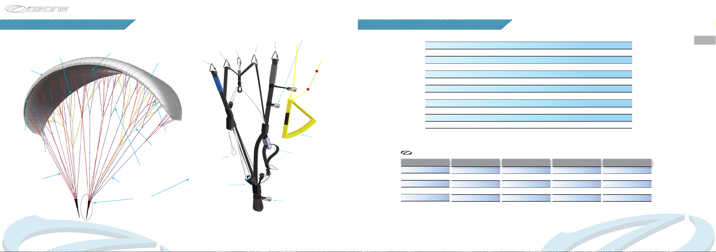
TECHNICAL DRAWINGS
Trailing
Edge
Leading
Edge
Cell
Openings
Butt Hole
Riser
Lines
Lower Surface
Stabilo Line
Risers
Middle
Lines
Upper Surface
Upper
Lines
Brake
Lines
Baby A
Riser
A
Riser
Brummel Hook
for Speed System
Accelerator
Pulley
B
Riser
C
Riser
D
Riser
AM Steering Pulley
Adjustable Brake
Pulley
TST
Handle
Brake
Handle
Trimmer
TECHNICAL SPECIFICATIONS
14
No. of Cells
Projected Area (m2)
Flat Area (m2)
Projected Span (m)
Flat Span (m)
Projected Aspect Ratio
Flat Aspect Ratio
Root Chord (m)
Glider Weight (Kg)
EN Weight Range (Kg)
PPG Weight Range (Kg)
Certication DGAC EN/LTF DGAC DGAC DGAC DGAC DGAC DGAC DGAC
Riser Lengths
Trim -white line position
A 600mm
2
A
B 600mm
C 600mm
D 600mm
600mm
Trim - slow position
A 600mm
2
A
B 580mm
C 560mm
D 540mm
56 56 56 56 56 56 56
11.97 12.8 13.7 14.5 16.2 17.9 19.7
14 15 16 17 19 21 23
7.01 7.33 7.57 7.81 8.25 8.68 9.08
8.89 9.21 9.51 9.8 10.36 10.89 11.4
4.19 4.19 4.19 4.19 4.19 4.19 4.19
5.65 5.65 5.65 5.65 5.65 5.65 5.65
1.99 2.06 2.12 2.19 2.31 2.43 2.55
3.58
55-80
55-110 55-120 55-130 65-140 75-150 85-160 95-170
590mm
15 16
3.85
55-90
Trim - released
A 600mm
A
B 622mm
C 644mm
D 665mm
3.98 4.17 4.47 4.78 5.1
55-90 65-95 75-105 85-115
2
611mm
17 19
Trim nuetral+Accelerated
A 430mm
2
A
B 515mm
C 600mm
D 685mm
473mm
21 23
95-125
Trim released+Accelerated
A 430mm
2
A
483mm
B 535mm
C 630mm
D 730mm
EN
36
Main Hangpoint
to Harness Karabiner
Note: Standard PK risers not pro version.
Note: Standard PK risers not pro version.
37
Page 22

1258 Route de Grasse
Le Bar sur Loup
06620
France
 Loading...