

Ozone Speedster 2 Owner's Manual

Pilots Manual
THANK YOU
CONTENTS
EN
01
Thank You 01
Warning 02
Team Ozone 03
Your Speedster 2 04
Risers 05
Preparation 09
Basic Flight Techniques 11
Advanced Flying Techniques 16
Incidents 18
Caring and Maintenance 20
Limitations 27
Ozone Quality 29
Technical Specications 30
Drawing/Riser lengths 31
Line diagram 32
Materials 33
EN v1.3 Jan 2017
T
hank you for choosing to y Ozone. As a team of free ying enthusiasts, competitors and adventurers,
Ozone’s mission is to build agile paragliders of the highest quality with cutting edge designs,
performance and maximum security.
Condence and belief in your paraglider is a far greater asset than any small gains in performance - ask
any of the Ozone pilots on your local hills, or those who have taken our gliders on ground-breaking
adventures or stood on podiums around the world. All our research and development is concentrated on
creating the best handling/performance characteristics possible with optimum security. Our development
team is based in the south of France. This area - which includes the sites of Gourdon, Monaco and Col de
Bleyne - guarantees us more than 300 yable days per year, this is a great asset in the development of
the Ozone range.
As pilots we fully understand just how big an investment a new paraglider is. We know that quality and
value for money are essential considerations when choosing a new wing, so to keep costs low and quality
high we manufacture all of our products in our own production facility. During production our wings undergo
numerous rigorous quality control checks that are fully traceable, this way we can guarantee that all of our
paragliders meet the same high standards.
It is essential that you read this manual before ying your wing for the rst time. The manual will help you
get the most out of your new wing, it details information about the design, tips and advice on how best
to use it and how to care for your wing to ensure it has a long life and retains a high resale value. For the
latest updates, including all technical datas please refer to the online version. This can be found on the
product’s page on at www.yozone.com
If you need any further information about any of our products please check yozone.com or contact your
local dealer, school or any of us here at Ozone.
Safe Flying!
Team Ozone

WARNING
TEAM OZONE
EN
03
02
• Paragliding/Paramotoring is a potentially dangerous sport that can cause serious injury
including bodily harm, paralysis and death. Flying an Ozone paraglider is undertaken with
the full knowledge of the involved risks.
• As the owner of an Ozone paraglider you take exclusive responsibility for all risks associated
with its use. Inappropriate use and or abuse of your equipment will increase these risks.
• Any liability claims resulting from use of this product towards the manufacturer, distributor
or dealers are excluded.
• Be prepared to practice as much as you can - especially ground handling, as this is a critical
aspect of paragliding. Poor control while on the ground is one of the most common causes
of accidents.
• Be ready to continue your learning by attending advanced courses to follow the evolution of
our sport, as techniques and materials keep improving.
• Use only certied paragliders, harnesses with protector and reserve parachutes that are free
from modication, and use them only within their certied weight ranges. Please remember
that ying a glider outside its certied conguration may jeopardise any insurance (e.g.
liability, life etc) you have. It is your responsibility as the pilot to verify your insurance cover.
• Make sure you complete a thorough daily and preight inspection of all of your equipment.
Never attempt ying with unsuitable or damaged equipment.
• Always wear a helmet, gloves and boots.
• All pilots should have the appropriate level of license for their respective country and third
party insurance.
• Make sure that you are physically and mentally healthy before ying.
• Choose the correct wing, harness and conditions for your level of experience.
• Pay special attention to the terrain you will be ying and the weather conditions before
you launch. If you are unsure do not y, and always add a large safety margin to all your
decisions.
• NEVER y your glider in rain, snow, strong wind, clouds or turbulent weather
conditions.
• If you use good, safe judgment you will enjoy many years of paragliding/paramotoring.
Everyone at Ozone continues to be driven by our passion for ying, our love of adventure
and our quest to see Ozone’s paraglider development create better, safer and more versatile
paragliders.
The design team consists of David Dagault, Luc Armant, Fred Pieri, Russell Ogden, Honorin
Hamard, Emilia Plak and Alex Mateos.
Dav has a wealth of experience in competition ying, XC, XAlps and paraglider design. Luc,
a dedicated XC and competition addict has a background in naval architecture. Fred, our
resident geek is a mathematician, mechanical engineer and vol Biv specialist. Russ is a
competition pilot and test pilot with 1000s of hours testing experience. Honorin has been
ying since he was 13, naturally talented, he has already become world champion. Between
them, they bring a wealth of knowledge, ideas and experience and work closely together in
the design and testing process.
Former female World champion, Emilia Plak manages the paramotor department, she is
helped by Alex Mateos. As two of the nest pilots in the world holding World, European and
French Paramotoring champion titles between them, they offer valuable advice and feedback
throughout the development process, helping to produce the perfect blend of safety, speed
and performance.
Mike Cavanagh is the boss and multiple winner of the UK XC league, when not out ying he
generally keeps control of the mayhem. Promotion and team pilots are organised by BASE
jumping legend and mini wing specialist Matt Gerdes. He works closely with graphic designer
Loren Cox. Loren is a keen pilot from Salt Lake city, USA. Back in the ofce Karine Marconi,
Chloe Vila and Isabelle Martinez run the show. These wonderful ladies look after the ordering
system, the dealers, the design team and the general day to day running of the company without them it would be chaos.
Our manufacturing facility in Vietnam is headed up by Dr Dave Pilkington who works
relentlessly manufacturing gliders and producing prototypes as well as researching materials
and manufacturing processes for our future products. He is backed up by a superb team
managed by Khanh and Phong with over 700 production staff.
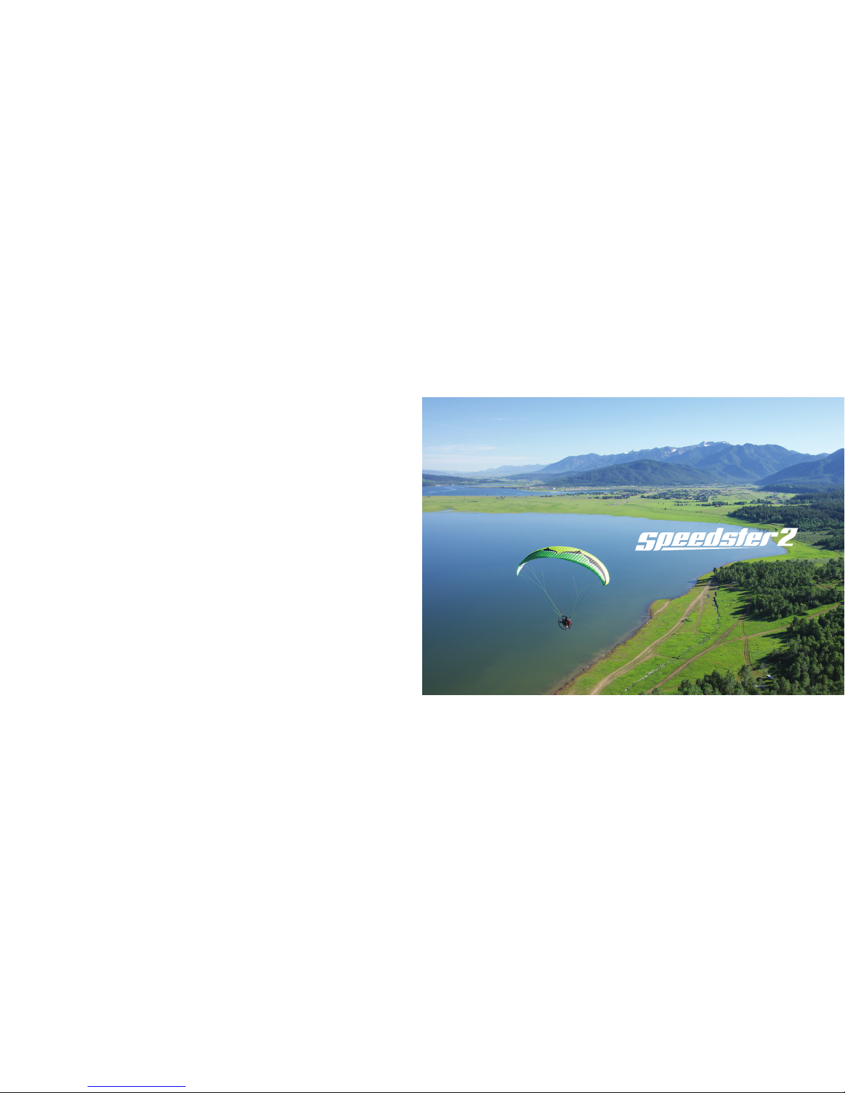
YOUR SPEEDSTER 2
RISERS
EN
05
04
Replacing the iconic Speedster was never going to be easy, the all new design retains a similar
character to its predecessor but includes technological improvements to further improve the
handling, stability and efciency.
The Speedster 2 features a faster top speed than its predecessor, the reduced line drag and
optimised prole have made this new wing an incredible tool in accelerated ight. In addition
to the increased speed, the Speedster 2 is more efcient, requiring less fuel and less power
to maintain top speed.
The OZRP shark nose reex prole, along with the modied aspect ratio and optimized internal
structure, has sharpened the handling, increased the inherent stability, and improved the sail
cohesion – all of which means that the wing is easier and more forgiving to y, especially in
turbulent air. The fact that the aspect ratio has been reduced alongside an increase in overall
performance means that the Speedster 2 is a huge step forward from the original Speedster.
The Speedster 2’s handling is great fun; it is precise, intuitive, and extremely resistant to
spin when being own in deep brakes. On the ground, the ination characteristics have been
improved - the Speedster 2 comes up quickly and evenly, especially in nil or light winds.
The Speedster 2 comes with a completely new riser system, which includes the innovative 2D
TST device for improved precision in accelerated ight, multiple brake pulley positions, and
extended trimmer range.
Certied DGAC, EN C*and load tested to 243kgs (5.25g), the Speedster 2 is available in 4
sizes 22**, 24, 26 and 28 to cover a wide range of pilot weight and power unit combinations.
4 standard colour schemes and custom colours.
*Trim speed only, trimmers set to the slow position.
**DGAC certication only
The updated risers feature long range trimmers; stronger brake handle magnets; TST and
innovative 2D steering systems; fully adjustable brake pulley height settings and coloured A
risers for easy identication. See page 30.
Trimmers
The Speedster is supplied with a trim riser set. The ‘neutral’ or standard position is when the
trimmers are pulled all the way down and it is in this position that the wing is certied. The
trimmers can be set to the white line for better ination behaviour during take-off. This is
especially useful in light winds and/or at high altitudes. The standard (certied) trim setting
is ideal for climbing under power, whilst thermalling and when the air is turbulent. Brake
pressure is lighter and the handling at its best at the standard (certied) trim setting. To
increase cruise speed you can use the accelerator system, release the trimmers, or do both.
Using the speed system has exactly the same effect as releasing the trimmers so it is safe
and possible to y with the trimmers in the standard position whilst using the full range of
the speed system.
In turbulent air the reex prole is very stable. It will resist reasonable levels of turbulence
with a high resistance to collapse without pilot input. The faster the wing is own the more
inherent stability there is, as the reex has a greater effect. In mild turbulence it may be best
to not attempt to y the wing actively and let the prole absorb the turbulence itself, indeed
small applications of the brakes can reduce the inherent stability of the prole. However in
very strong turbulence Ozone recommends to return the trimmers to the neutral position
(pulled down) and ying the glider actively. This way, you will be in the best position to react
correctly should an incident occur.
Accelerator System
The risers feature an accelerator system with ball bearing pulleys for easy, comfortable high
speed cruising. Using the speed system has exactly the same effect as releasing the trimmers.
Either can be used in any combination to accelerate the wing, but be careful, fully accelerated
with trimmers released is very fast and should only be used in calm conditions and sufcient
altitude.
IMPORTANT
In thermic or turbulent
air pull the trimmers
to the slow or neutral
position or at least to
the white stitch line or
accept a higher risk of
collapse.
IMPORTANT
When accelerated
directional control
should be maintained
with the TST system or
the Tube Ball handle
(if the 2D system is
installed). Do NOT use
the brakes.
EN
07
06
Brake Lines
The brake line lengths have been set carefully during testing. We feel it is better to have
slightly long brake lines and to y with a wrap when necessary.
• Ensure both main brake lines are of equal length.
• If a brake handle has been removed, check that its line is still routed through the pulley
when it is replaced.
• When the brake handles are released in ight, the brake lines should be slack. There
must be a substantial “bow” in them to guarantee no deformation of the trailing edge.
• There must be a minimum of 10cm of free play before the brakes begin to deform the
trailing edge. This prevents the trailing edge from being deformed when using the speed
system or when controlling the wing with the TST.
Adjustable Brake Pulley Position
The height of the brake line pulley can be adjusted according to pilot preference and to suite
the power unit’s hang points height. Higher settings are for low hang point motors whilst a
middle or lower setting are for units with higher hang points.
To adjust the pulley height, rst remove them from the risers and re-attach at the desired
position, then undo the Velcro magnet attachments and re-attach a few cms below the new
pulley position. If you lower the pulley height, you must also lengthen the brake lines and TST
lines accordingly. Moving the pulleys to the middle position on the risers requires the addition
of about 10cm to the overall brake/TST line lengths (measured from the mark on the lines).
Moving to the lowest position requires an additional 20cm from the marks.
Tip Steering System
The Tip Steering System (TST) uses ergonomic handles for control of the wing during
accelerated ight. Located on the B risers, the handles are easily accessible and linked to the
very tips of the wing, giving high levels of precision and comfort for high speed cruising or
accurate low level carving. The TST allows for precise handling without the need to use the
brakes, it is not necessary to use large control movements to effect a turn so be progressive
and gentle at rst until you are familiar with the handling characteristics. The attachment
height of the TST handles can also be adjusted according to your comfort, ying style and
motor unit.
For directional control whilst ying with the speed bar only use the TST. DO NOT use the brakes
alone. Application of brake when the wing is at a low angle of attack has a negative effect on
the reex prole causing loss of precision, adverse roll, and reduced collapse resistance. In
accelerated ight the tip steering system can be used for both directional control - to keep a
straight heading and for effecting nice smooth turns. It becomes more precise the faster you
y.
When using the TST, it is advised to keep the brake handles through the wrists. This is in case
of an engine failure or loss of control. It is therefore necessary to ensure that the brake lines
are adjusted in such a way that they are not activated when using the tip steering - make sure
the brake and TST lines are set correctly.
2D Steering System
The optional 2D system has been developed for competition slalom racing where precise
control of the trailing edge is absolutely necessary. The 2D system combines the brake lines
and the TST so that the tip lines (TST) alone can be engaged, or only the brakes in the middle
part of the wing engaged, or a combination of both.
The 2D system can be set up and adjusted according to your personal preference, ying
style and power unit hang point heights. The lower the brake pulley position on the risers the
more effective the 2D steering system becomes, however the standard setting, as described
below, is a good starting point for low hang point power units and a good compromise between
comfort and ease of use.
Pushing the handle away from your body engages the brakes in the middle of the trailing
edge (Scheme 1), whilst pulling the hand close towards your body will engage the wing tips
(Scheme 2). Pulling the brakes down in the normal manner will engage both the TST and the
brakes (Scheme 3).
IMPORTANT
In the unlikely
event of a brake line
snapping in ight, or
a handle becoming
detached, the glider
can be own by gently
pulling the rear risers
(D-risers), or the TST
for directional control.
IMPORTANT
If you adjust the
brake pulley height,
you MUST re lengthen
the brake lines
accordingly.
IMPORTANT
When accelerated
directional control
should be maintained
with the TST system or
the Tube Ball handle
(if the 2D system is
installed). Do NOT use
the brakes.
 Loading...