

Ozito TSF-1211U Original Instructions Manual
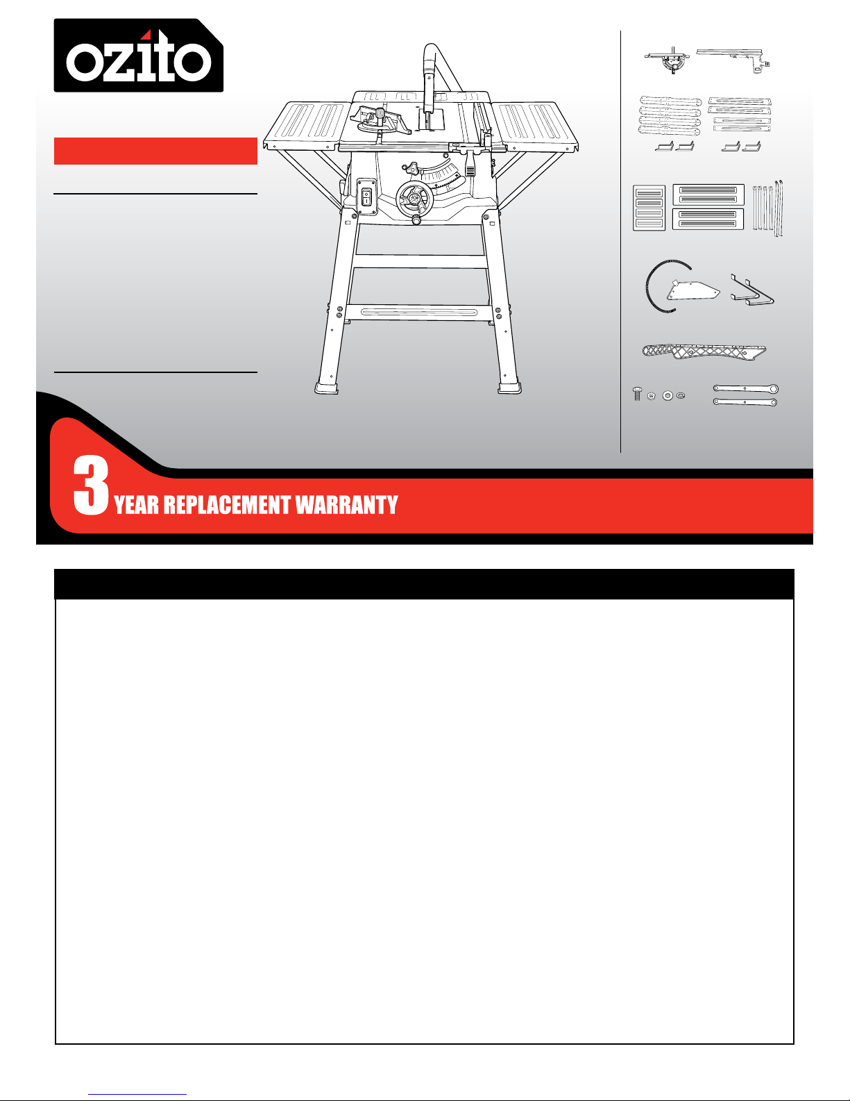
TABLE SAW
2000W 250mm
ORIGINAL INSTRUCTIONS
SPECIFICATIONS
Motor: 2000W (S6 25%) 1800W (S1)
No Load Speed: 5,000/min
Blade: Ø250mm x Ø30 x 2.8mm
Bevel Angle: 0º-45° left
Blade Height Adj: 0-85mm
Max. Cutting Capacity:
Bevel 90°: 85mm
Bevel 45°: 65mm
Table Size: 640 x 490mm
With Side Ext.: 640 x 940mm
Rear Extension: 225 x 490mm
Dust Port: Ø36mm
Weight: 20kg
TSF-1211U
WHAT’S IN THE BOX
WARRANTY
ozito-diy.co.uk
0816
Base Frame Legs x 4,
Cross Struts x 4, Feet x 4
Push Stick
Sliding Mitre
Gauge
Blade Guard & Dust Extractor
Hose, Stabilizing Brackets x 2
Table Extensions x 3
Support Struts x 6
Bolts, Spring & Flat Washers,
Nuts x 32, Spanners x 2
0º 5º
10º
15º
20º
25º
22.5º
30º
45º
Rip Fence
OZITO UK Unit 9 Stadium Court, Wirral International Business Park, Plantation Road, Bromborough, Wirral, CH62 3QG
All of our products undergo strict quality checks to ensure that they reach
you in perfect condition. In the unlikely event that your device develops a
fault, please contact our service department at the address shown on this
guarantee card. You can also contact us by telephone using the customer
service number shown. Please note the following terms under which
guarantee claims can be made:
1. These warranty terms regulate additional warranty services, which the
manufacturer mentioned below promises to buyers of its new products
in addition to their statutory guarantee claims are not affected by this
guarantee. Our guarantee is free of charge to you.
2. The warranty services only covers defects due to material or
manufacturing faults on a product which you have bought from the
manufacturer mentioned below are limited to either the rectication of said
defects on the product or the replacement of the product, whichever we
prefer.
Please note that our devices are not designed for use in commercial, trade
or professional applications. A guarantee contract will not be created if the
device has been used by commercial, trade or industrial business or has
been exposed to similar stresses during the guarantee period.
3. The following are not covered by our guarantee:
- Damage to the device caused by a failure to follow the assembly
instructions or due to incorrect installation, a failure to follow the operating
instructions (for example connecting it to an incorrect mains voltage or
current type) or a failure to follow the maintenance and safety instructions
or by exposing the device to abnormal environmental conditions or by lack
of care and maintenance.
- Damage to the device caused by abuse or incorrect use (for example
overloading the device or the use or unapproved tools or accessories),
ingress of foreign bodies into the device (such as sand, stones or dust,
transport damage), the use of force or damage caused by external forces
(for example by dropping it).
- Damage to the device or parts of the device caused by normal or natural
wear or tear or by normal use of the device.
4. Your Product is guaranteed for a period of 36 months from the original
date of purchase and is intended for DIY (Do It Yourself) use only. Lithium
Ion batteries and chargers are covered by a 12 month warranty. Warranty
excludes consumable parts. Guarantee claims should be submitted
before the end of the guarantee period within two weeks of the defect
being noticed. No guarantee claims will be accepted after the end of the
guarantee period. The original guarantee period remains applicable to the
device even if repairs are carried out or parts are replaced. In such cases,
the work performed or parts tted will not result in an extension of the
guarantee period, and no new guarantee will become active for the work
performed or parts tted. This also applies if an on-site service is used.
IN ORDER TO MAKE A CLAIM UNDER THIS WARRANTY YOU MUST
RETURN THE PRODUCT TO THE PLACE OF PURCHASE WITH YOUR
REGISTER RECEIPT.
Please refer to the restrictions of this warranty concerning wearing parts,
consumables and missing parts as set out in the service information in
these operating instructions.
CUSTOMER SERVICE HELPLINE
GB: 0151 294 4488
IRL: 1850 882711
Ozito-diy.co.uk
EH-Art.-No.: 4340542 I.-No.: 11016

3
ONLINE MANUAL
Scan this QR Code with your
mobile device to take you to
the online manual.
1. Side table extension
2. Rear table extension
3. Sliding mitre gauge
4. Dust extractor hose
5. Blade guard
6. Rip fence
7. Support strut
8. Stabilising bracket
9. Push stick
10. Guide rail
11. Table insert
12. Rip fence lever
13. ON/OFF switch
14. Bevel lock
15. Blade height & Bevel
adjustment
16. Bevel scale
TABLE SAW
KNOW YOUR PRODUCT
54 6
8
1. ADJUSTMENTS
For detailed assembly instruction see Assembly
Manual.
SETUP & PREPARATION
0º 5º
10º
15º
20º
25º
22.5º
30º
45º
32
9
14
7
WARNING! ENSURE THE TOOL IS SWITCHED OFF AND
DISCONNECTED FROM THE POWER SUPPLY BEFORE
PERFORMING ANY OF THE FOLLOWING PROCEDURES.
Cutting Depth
Bevel Angle
1. To lower the blade for a
smaller depth of cut, rotate
the blade height & bevel
adjustment clockwise.
3. Rotate the blade height
& bevel adjustment to the
desired angle using the
bevel scale.
2. Push and hold the blade
height & bevel adjustment
dial in to engage the bevel
gear.
2. To raise the blade for a
larger depth of cut, rotate
the blade height & bevel
adjustment anti-clockwise.
4. Release the blade height & bevel adjustment dial, secure in place by
rotating the bevel lock clockwise.
1. Loosen the bevel lock by
rotating anti-clockwise.
12
13 15 16
11
10

2. SETTING THE RIP FENCE
Rip Fence Stop Height
Thin Material Thick Material
The rip fence supplied with the table saw has two different guide faces.
1 for thick material and 1 for thin material.
2. Slide the stop rail off and
re-insert the desired rail.
1. To change the stop
rail, loosen the 2
wing nuts.
3. Tighten the 2 wing nuts to lock in place.
Note: Rule of thumb: The rear end of the stop comes up against an
imaginary line that begins roughly at the centre of the blade and runs
at an angle of 45° to the rear.
1. Set the required cutting
width.
2. Loosen the wing nuts and
push the stop rail forward
until it touches the imaginary
45° line.
3. Retighten the wing nuts.
Rip Fence Cutting Width
2. Slide the rip fence
to the desired
dimension using the
scale of the guide
rail.
0º 5º
10º
15º
20º
25º
22.5º
30º
45º
The rip fence has to be used
when making longitudinal cuts in
wooden work pieces.
The rip fence can be mounted on
either side of the saw table.
1. Loosen the rip fence lever and
insert the fence into the table
guide rail.
3. Tighten the rip fence lever to
lock the rip fence in position.
Setting the Stop Length
45
0
The stop rail can be moved in a longitudinal direction in order to
prevent the workpiece from becoming jammed.
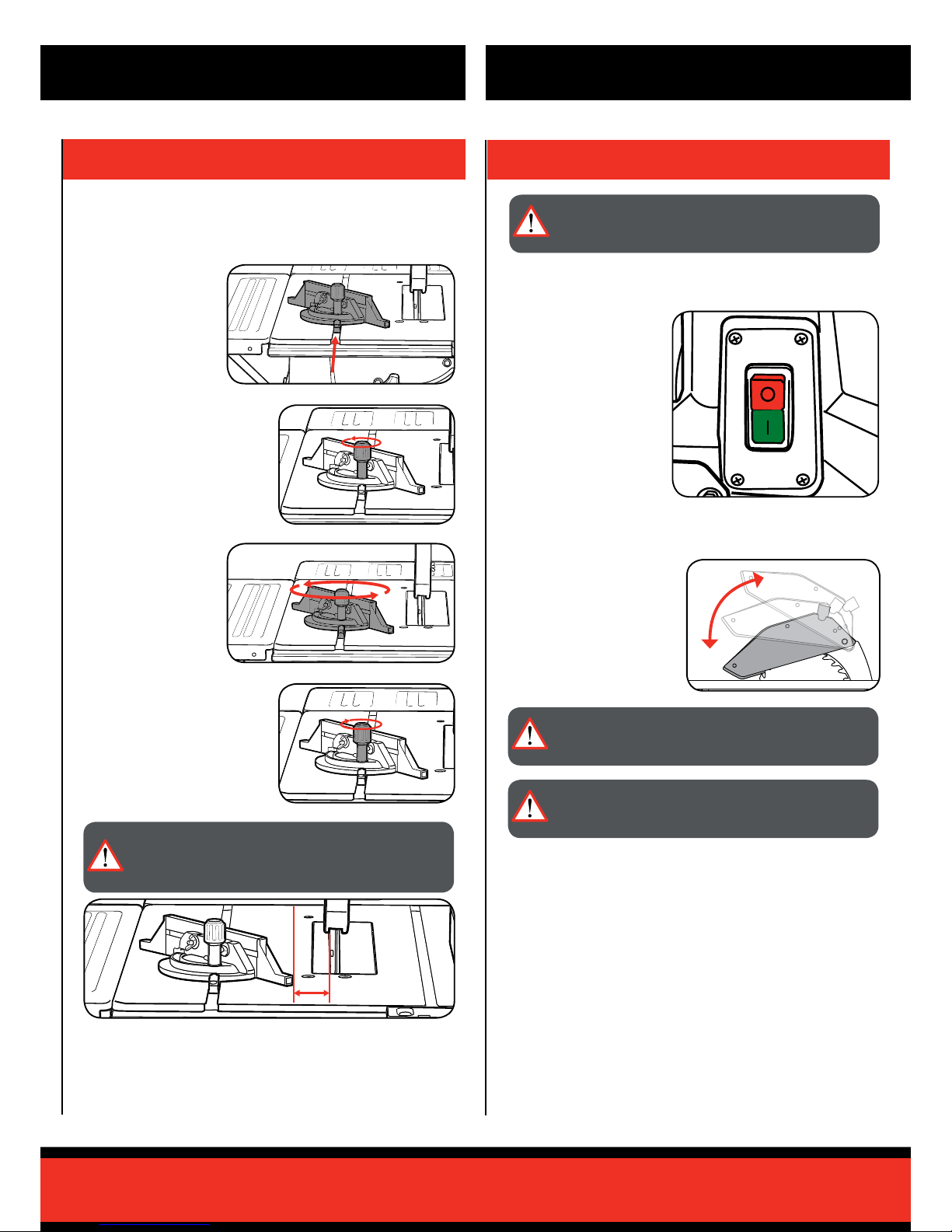
4. USING THE TABLE SAW
3. SETTING THE MITRE GAUGE
OPERATION
CAUTION! TO REDUCE THE RISK OF ELECTRICAL
SHOCK, THE USE OF A RESIDUAL CURRENT DEVICE
(RATED 30mA OR LESS) IS RECOMMENDED.
Using the Sliding Mitre Gauge
The sliding mitre gauge can be tted into 1 of the 2 grooves in the table
and can be used to easily perform mitre angle cuts.
2. Loosen the knurled screw to
adjust the mitre angle.
4. Lock the mitre angle by
tightening the knurled screw.
1. Slide the rail of the
mitre gauge into 1 of
the grooves of the
table.
3. Rotate the mitre
gauge to the desired
angle using the mitre
scale.
20mm
IMPORTANT! DO NOT PUSH THE MITRE GAUGE STOP
RAIL TOO FAR TOWARD THE BLADE. THE DISTANCE
BETWEEN THE STOP RAIL AND THE BLADE SHOULD BE
APPROX. 20MM.
IMPORTANT! THE BLADE GUARD MUST ALWAYS BE
LOWERED OVER THE WORK PIECE AND MOUNTED
SECURELY BEFORE YOU BEGIN TO CUT.
IMPORTANT! AFTER EVERY NEW ADJUSTMENT WE
RECOMMEND YOU TO MAKE A TRIAL CUT IN ORDER TO
CHECK THE NEW SETTINGS.
On / Off Switch
1. To turn the saw ON, press
the green button "I".
Note: Wait for the blade to
reach its maximum speed
before commencing with the
cut.
2. To turn the saw OFF,
press the red button "0".
Blade Guard
1. The blade guard must be
able to move freely, adjust
if necessary (refer to
Assembly Manual).
 Loading...