

Ozito SCMS-10STAND User Manual
SLIDING
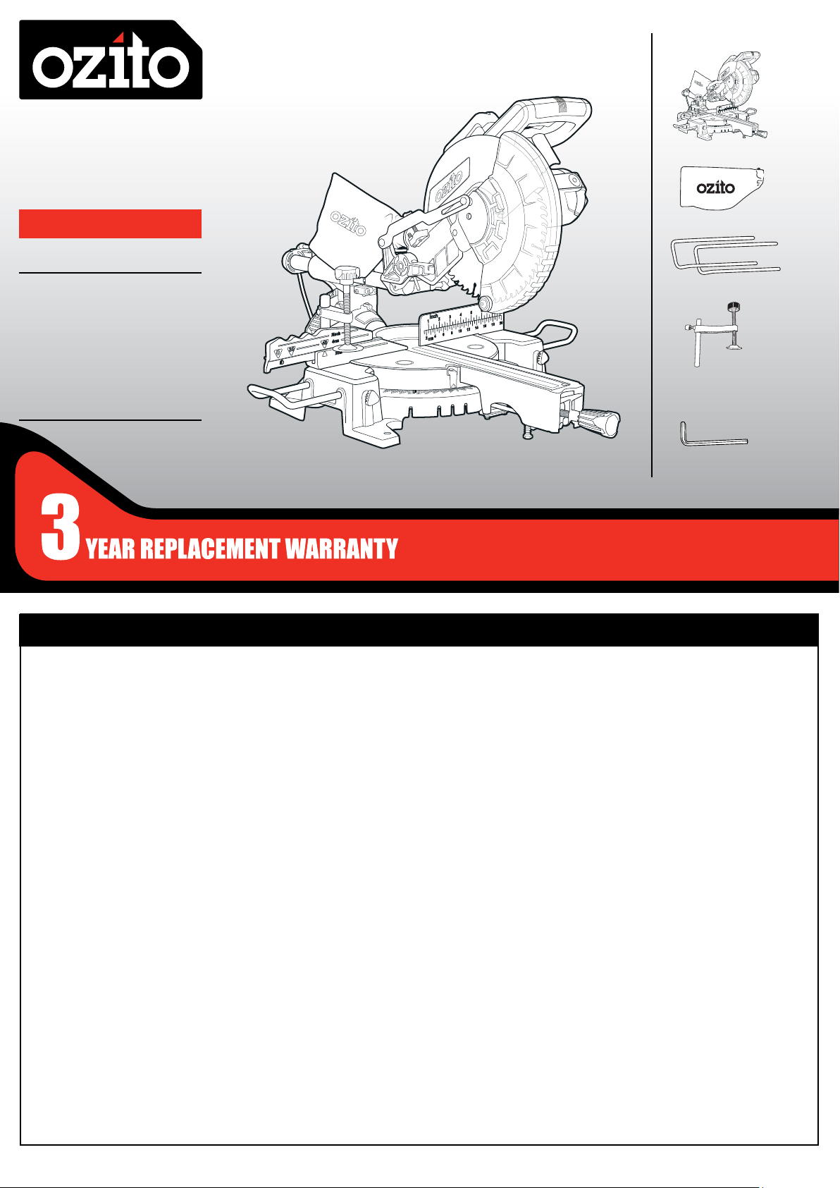
WHAT’S IN THE BOX
COMPOUND
MITRE SAW
254mm (10”)
INSTRUCTION MANUAL
SPECIFICATIONS
Motor: 1900W
No Load Speed: 4,800/min
Blade: Ø254mm x Ø25.4 x 48T
Mitre Angle: 0-45° left & right
Bevel Angle: 0-45° left
Max. Cutting Capacity:
Mitre 0° x Bevel 90°: 70 x 310mm
Mitre 45°x Bevel 90°: 70 x 210mm
Mitre 0°x Bevel 45°: 40 x 310mm
Mitre 45°x Bevel 45°: 40 x 210mm
ozito.com.au
Compound Mitre Saw
Dust Bag
Material Support Bar x 2
Material Clamp
Hex Key
SCMS-10STAND
WARRANTY
IN ORDER TO MAKE A CLAIM UNDER THIS
WARRANTY YOU MUST RETURN THE PRODUCT
TO YOUR NEAREST BUNNINGS WAREHOUSE WITH
YOUR BUNNINGS REGISTER RECEIPT. PRIOR TO
RETURNING YOUR PRODUCT FOR WARRANTY
PLEASE TELEPHONE OUR CUSTOMER SERVICE
HELPLINE:
Australia 1800 069 486
New Zealand 0508 069 486
TO ENSURE A SPEEDY RESPONSE PLEASE
HAVE THE MODEL NUMBER AND DATE OF
PURCHASE AVAILABLE. A CUSTOMER SERVICE
REPRESENTATIVE WILL TAKE YOUR CALL
AND ANSWER ANY QUESTIONS YOU MAY
HAVE RELATING TO THE WARRANTY POLICY
OR PROCEDURE.
The benefits provided under this warranty are in addition
to other rights and remedies which are available to you at law.
Our goods come with guarantees that cannot be excluded
at law. You are entitled to a replacement or refund for a major
failure and for compensation for any other reasonably foreseeable
loss or damage. You are also entitled to have the goods repaired
or replaced if the goods fail to be of acceptable quality and the
failure does not amount to a major failure.
Generally you will be responsible for all costs associated with
a claim under this warranty, however, where you have suffered
any additional direct loss as a result of a defective product you
may be able to claim such expenses by contacting our customer
service helpline above.
3 YEAR REPLACEMENT WARRANTY
Your product is guaranteed for a period of 36 months from the
original date of purchase and is intended for DIY (Do It Yourself) use
only. If a product is defective it will be replaced in accordance with
the terms of this warranty. Warranty excludes consumable parts, for
example: blade, carbon brushes and dust bag.
WARNING
The following actions will result in the warranty being void.
• If the tool has been operated on a supply voltage other
than that specified on the tool.
• If the tool shows signs of damage or defects caused
by or resulting from abuse, accidents or alterations.
• Failure to perform maintenance as set out within the instruction
manual.
• If the tool is disassembled or tampered with in any way.
• Professional, industrial or high frequency use.
OZITO
Australia/New Zealand (Head Office) 1-23 Letcon Drive, Bangholme, Victoria, Australia 3175.
0917
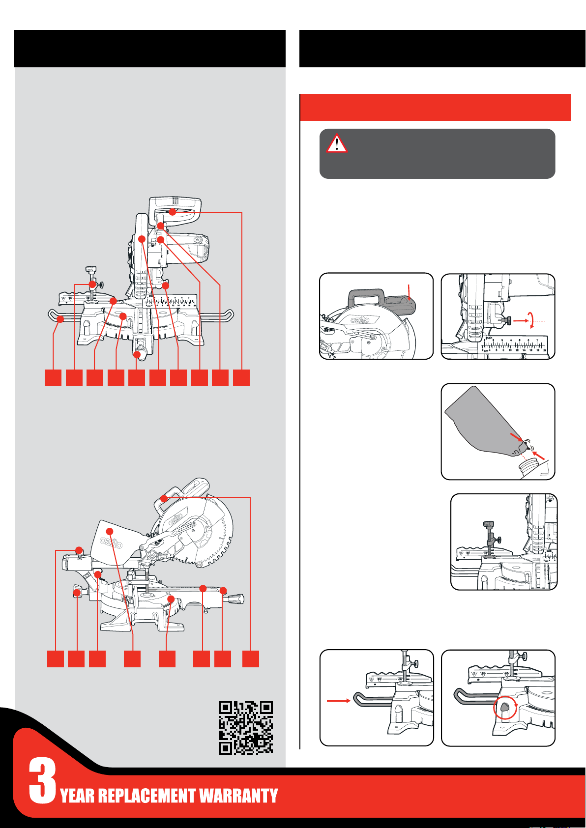
KNOW YOUR PRODUCT
SETUP & PREPARATION
MITRE SAW
1 Material Support Bar
2 Material Clamp
3 Fence
4 Mitre Table
5 Mitre Table Lock
1
2 3 4 5 6 7 8 9 10
11 Slide Lock
12 Bevel Lock
14 Dust Bag
13 Laser Guide
6 Retractable Safety Guard
7 Lock Down Pin
8 Spindle Lock Button
9 Release Lever
10 Trigger
15 Mitre Angle Pointer
16 Table Insert
17 Mitre Release
18 Carry Handle
1. ASSEMBLY
WARNING! ENSURE THE TOOL IS SWITCHED
OFF AND DISCONNECTED FROM THE POWER
SUPPLY BEFORE PERFORMING ANY OF THE
FOLLOWING PROCEDURES.
Unpacking
1. Remove foam packaging materials and using the carry handle,
carefully lift the mitre saw from its box and place it on a level
work surface.
2. Release cutting head from its transport position. While holding
the head of the saw down release the lock down pin by rotating
it 90 degrees.
Dust Bag
1. Squeeze the clamp at the
end of the dust bag, place
over the dust extraction
port.
11 12 13 14 15 16 17 18
ONLINE MANUAL
Scan this QR Code with your
mobile device to take you to
the online manual.
Material Clamp
Material clamp will assist
securing timber when making
cuts.
Note: The clamp can be
mounted on either the left or
right side of the blade.
Material Support Bars
1. Insert each bar into the
two holes located on
both sides of the base.
2. Tighten screw when in
place.
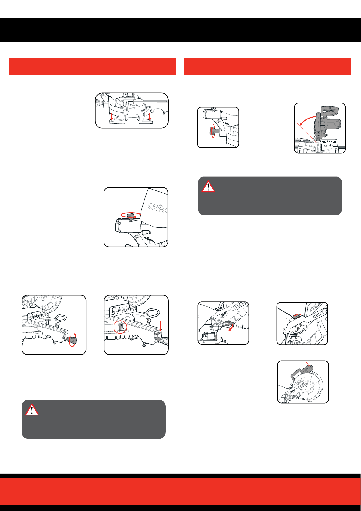
2. SET-UP AND ADJUSTMENTS
Bench Mounting
The base of the saw has
bench mounting holes that
can be used to mount it to a
workbench or mitre saw stand.
Use screws or bolts to secure.
Note: If required, the Mitre Saw can be mounted onto a 13mm piece
(or thicker) of plywood which can then be clamped to the work bench
or mitre saw stand. This provides the exibility to transport the Mitre
Saw to other work areas
Slide Lock
When cutting a narrow piece of
wood it is not necessary to use
the slide mechanism. In these
circumstances, push back the
cutting head and ensure the slide
locking knob is tight to prevent the
cutting head from sliding.
Mitre Angle Adjustment
1. Loosen mitre table lock
2. While pulling the mitre
release set the desired mitre
angle (left or right) as shown
by the mitre angle pointer
Bevel Angle Adjustment
1. Loosen bevel
lock.
3. Tighten bevel lock at selected angle.
Ensure the upper fence is moved out of the path of the blade.
WARNING!: ENSURE THE BEVEL LOCK IS
TIGHT BEFORE MAKING A CUT. FAILURE TO
DO SO MAY RESULT IN THE CUTTING HEAD
MOVING DURING OPERATION AND CAUSE
SERIOUS PERSONAL INJURY.
2. Tilt the cutting head to the desired
bevel angle
left as shown
by the bevel
angle pointer.
Trenching
Trenching refers to restricting the depth of cut and permits a “trench”
to be cut in the workpiece.
1. Ensure the cutting head is
raised, pull the trenching
stop out as far as it will go.
2. To adjust the trenching
depth rotate the trenching
depth adjustment screw.
Note: The mitre table features positive click stops at 0°, 15°, 22.5°,
31.6° and 45° for quick setting of common mitre angles.
3. Tighten mitre table lock at selected angle
WARNING! ENSURE THE MITRE TABLE LOCK
IS TIGHT BEFORE MAKING A CUT. FAILURE
TO DO SO MAY RESULT IN THE MITRE TABLE
MOVING DURING OPERATION AND CAUSE
SERIOUS PERSONAL INJURY.
3. To check that the blade
stops at the desired position,
lower the cutting head
until the trenching stop
adjustment screw touches
the trenching stop.
 Loading...