

Ozito MWR-135, MWR-090 Instruction Manual
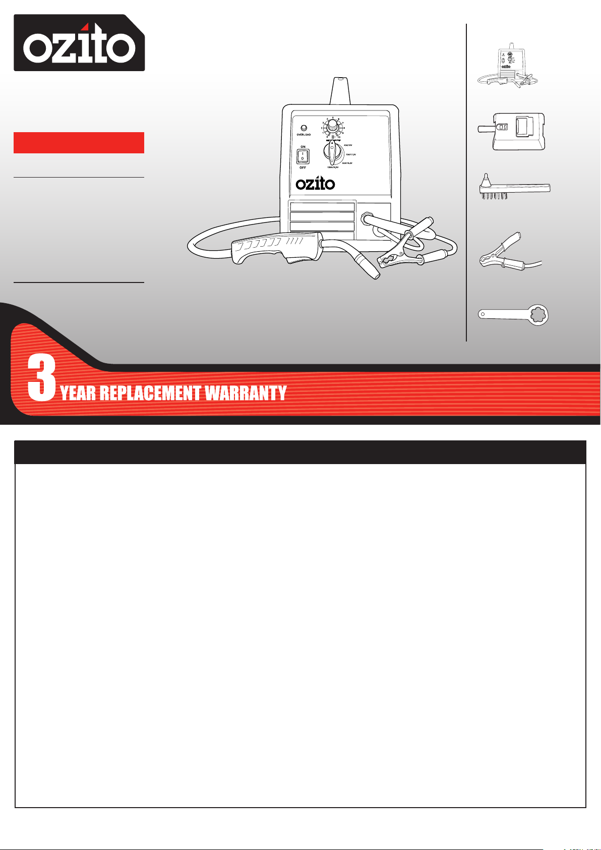
WHAT’S IN THE BOX
MIG
WELDER
120 Amp
INSTRUCTION MANUAL
SPECIFICATIONS
Input Voltage: 230-240V ~ 50Hz
Welding Current: 40 - 120A
Welding Wire Size: 0.6-0.8mm General Wire,
0.8-0.9mm Flux-Cored Wire
Duty Cycle: 60%@40A, 10%@120A
Insulation Type: Earthed Appliance (Class I)
Wire Spool Weight: 0.2kg to 5kg
Weight (tool only): 22.2kg
ozito.com.au
MIG Welder
Welding Mask
Chipping Hammer /
Wire Brush
Earth Clamp
Terminal Spanner
WARRANTY
IN ORDER TO MAKE A CLAIM UNDER THIS
WARRANTY YOU MUST RETURN THE PRODUCT
TO YOUR NEAREST BUNNINGS WAREHOUSE WITH
YOUR BUNNINGS REGISTER RECEIPT. PRIOR TO
RETURNING YOUR PRODUCT FOR WARRANTY
PLEASE TELEPHONE OUR CUSTOMER SERVICE
HELPLINE:
Australia 1800 069 486
New Zealand 0508 069 486
TO ENSURE A SPEEDY RESPONSE PLEASE
HAVE THE MODEL NUMBER AND DATE OF
PURCHASE AVAILABLE. A CUSTOMER SERVICE
REPRESENTATIVE WILL TAKE YOUR CALL
AND ANSWER ANY QUESTIONS YOU MAY
HAVE RELATING TO THE WARRANTY POLICY
OR PROCEDURE.
MWR-135
The benefits provided under this warranty are in addition
to other rights and remedies which are available to you at law.
Our goods come with guarantees that cannot be excluded
at law. You are entitled to a replacement or refund for a major
failure and for compensation for any other reasonably foreseeable
loss or damage. You are also entitled to have the goods repaired
or replaced if the goods fail to be of acceptable quality and the
failure does not amount to a major failure.
Generally you will be responsible for all costs associated with
a claim under this warranty, however, where you have suffered
any additional direct loss as a result of a defective product you
may be able to claim such expenses by contacting our customer
service helpline above.
3 YEAR REPLACEMENT WARRANTY
Your product is guaranteed for a period of 36 months from
the original date of purchase. If a product is defective it will
be replaced in accordance with the terms of this warranty.
Warranty excludes consumable parts, for example: welding masks
and combination wire brush and chipping hammers.
WARNING
The following actions will result in the warranty being void.
• If the tool has been operated on a supply voltage other
than that specified on the tool.
• If the tool shows signs of damage or defects caused
by or resulting from abuse, accidents or alterations.
• Failure to perform maintenance as set out within the
instruction manual.
• If the tool is disassembled or tampered with in any way.
• Professional, industrial or high frequency use.
OZITO Australia/New Zealand (Head Office) 1-23 Letcon Drive, Bangholme, Victoria, Australia 3175.
1014
KNOW YOUR PRODUCT
SETUP & PREPARATION
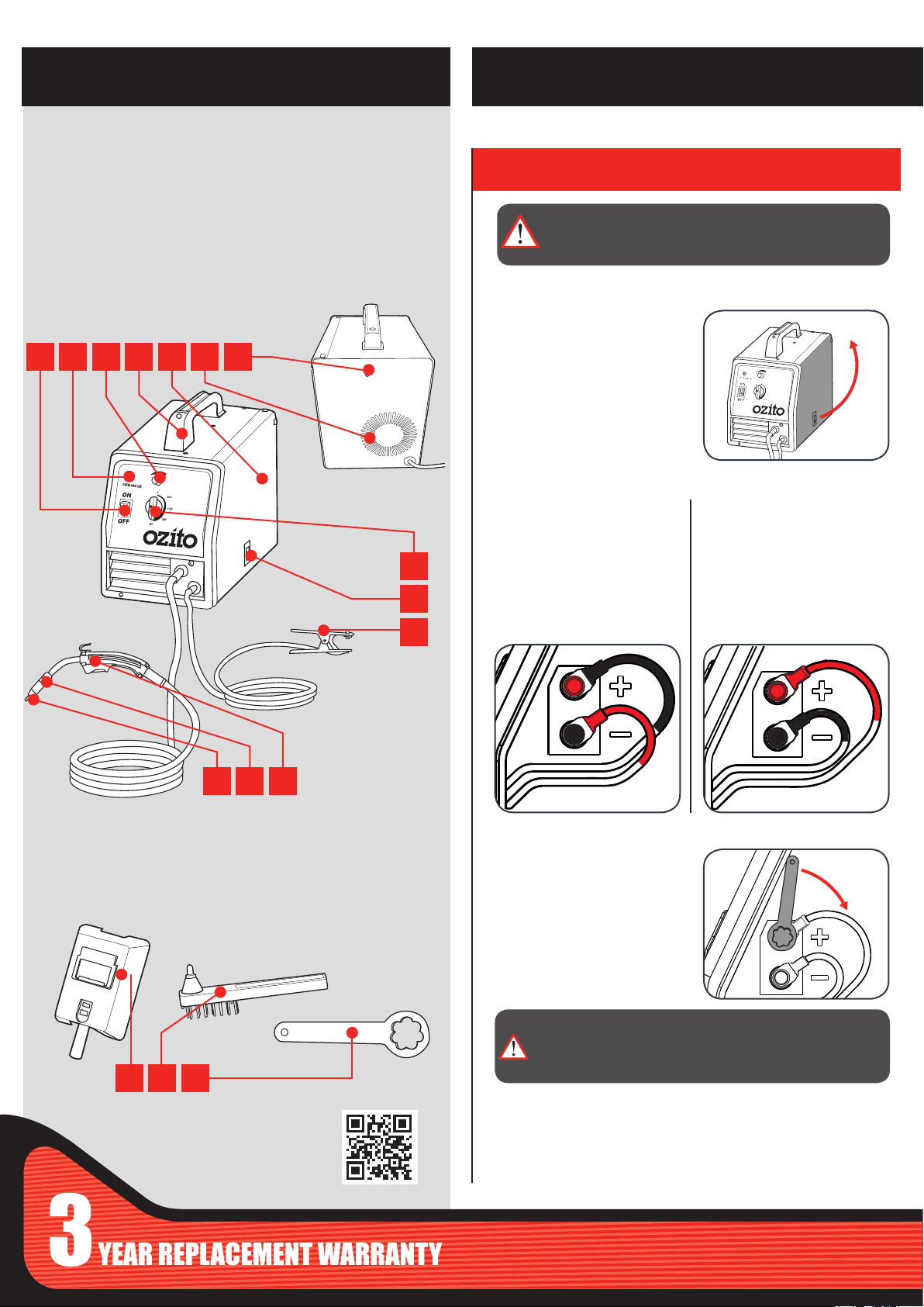
MIG WELDER
1 On/Off Switch
2 Overload Protection LED
3 Wire Feed Speed
4 Carry Handle
5 Side Cover
6 Internal Cooling Fan
7 Welder Gas Intake Barb
1 2 3 4 5 6 7
8 Output Voltage Control Dial
9 Side Cover Release Lever
10 Earth Clamp
11 Torch Tip
12 Shroud
13 MIG Torch
8
9
10
1. TERMINAL CONFIGURATION
WARNING: ENSURE THE TOOL IS SWITCHED OFF AND
DISCONNECTED FROM THE POWER SUPPLY BEFORE
PERFORMING ANY OF THE FOLLOWING STEPS.
Setting the Welding Current for Gasless or Gas Shielded
1 Open the side cover by
raising the side cover
release lever.
Gasless Welding Mode Gas Shielded Welding Mode
2 Connect the positive
welding cable (red) to the
negative terminal and the
negative welding cable
(black) to the positive
terminal.
2 Connect the positive
welding cable (red) to the
positive terminal and the
negative welding cable
(black) to the negative
terminal.
ACCESSORIES
14 Welding Mask
15 Chipping Hammer / Wire
Brush
14 15 16
ONLINE MANUAL
Scan this QR Code with your
mobile device to take you to
the online manual.
11
12 13
16 Terminal Spanner
3 Ensure that the terminals
are secure by tightening
the terminal knobs using
the terminal spanner.
WARNING: TERMINAL KNOBS MUST BE SECURELY
TIGHTENED PRIOR TO OPERATION. LOOSE OR
INCORRECT FASTENING MAY CAUSE THE CONNECTION
TO OVERHEAT OR BURN.
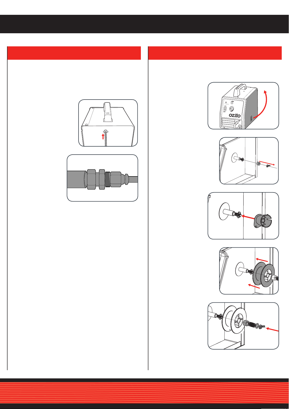
2. SHIELDED GAS WELDING SETUP 3. FITTING THE WELDING WIRE COIL
Drive
washer (c)
Drive
shaft (a)
5.0kg Coil
adaptor (e)
Drive
washer (c)
Drive
shaft (a)
5.0kg Coil
adaptor (e)
Attaching the Shielding Gas Hose and Regulator
When using a shielding gas with the MIG welder, you will
require additional hoses and gauges. These additional
accessories are available at your local gas supplier and are not
included with your MIG welder.
1 Connect the hose to the
welder gas intake barb
and secure in place with
the appropriate hose
clamp.
2 When using a
shielding gas with
a disposable argon
gas bottle, you may
need to purchase
a hose reducing
adaptor from your
gas supplier.
• Check with your local gas supplier for their recommendations
of the required gas mixture and ow rate for your MIG welder.
• Check all of the connections to the gauges and the shielding
gas bottle for leaks prior to commencing to weld.
The MIG welder is supplied with a 0.2kg coil of 0.8mm gasless
welding wire. Welding wire up to 5kg can be tted to this welder
using the 5kg coil adaptor.
1 Open the side cover
by lifting the side
cover release lever.
2 Remove the wing nut by
rotating anti-clockwise and
remove the drive washer.
3 If a 5kg wire coil is
to be tted, slide the
coil adaptor onto
the wire drive shaft.
Note: This step can
be skipped if a smaller
wire coil is to be tted.
4 Slide the welding wire coil
onto the shaft.
5 Align the drive
washer lug with
the slot in the drive
shaft and secure
with the wing nut
but do not over
tighten.
Note: Over tightening of the wing nut will restrict the wire feed
rate and can cause damage to the wire feed motor or irregular
welding.
 Loading...