

Page 1
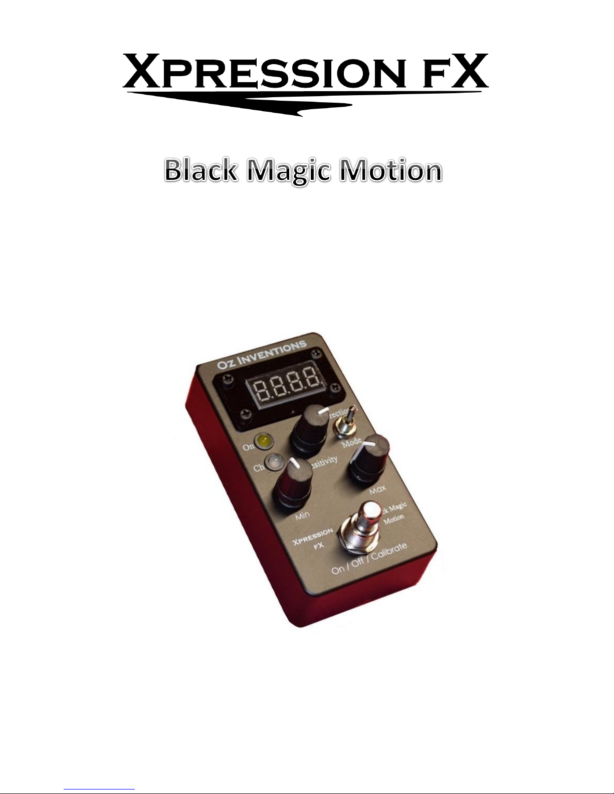
Modulator - Receiver
User guide
Page 2

2
© Oz inventions
Version 1.8
Contents
Declaration of compliance ......................................................................................................................... 5
Please read these two very important messages ........................................................................................ 6
Provided items ........................................................................................................................................... 7
Safety and care .......................................................................................................................................... 7
Warranty ................................................................................................................................................... 8
Power ........................................................................................................................................................ 8
Introduction ............................................................................................................................................... 9
Controls and sockets overview ..................................................................................................................10
Connecting................................................................................................................................................11
Connecting the expression jack .............................................................................................................11
Connecting the DC power adapter ........................................................................................................12
Antenna ................................................................................................................................................12
Connecting multiple receivers ...............................................................................................................13
Main indicator lights .................................................................................................................................14
ON ........................................................................................................................................................14
Ch .........................................................................................................................................................14
Minor indicator lights ................................................................................................................................14
Indicator lights in normal use mode ......................................................................................................14
Indicator lights in menu mode ...............................................................................................................14
Controls ....................................................................................................................................................15
Modulation mode switch ......................................................................................................................15
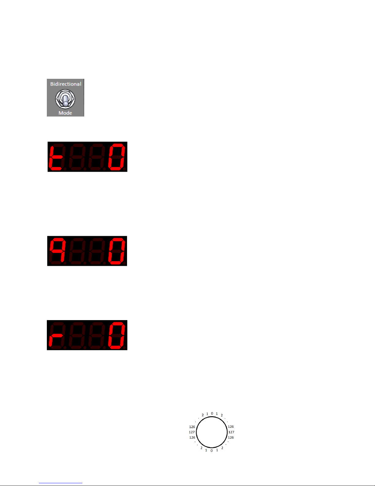
Bidirectional switch ...............................................................................................................................17
Sensitivity control (0 – 99) .....................................................................................................................17
Min depth (0 – 127) ..............................................................................................................................18
Max depth ............................................................................................................................................18
Display ......................................................................................................................................................20
Display in normal use mode ..................................................................................................................20
Indicator lights in normal use mode ......................................................................................................20
Display in menu mode ...........................................................................................................................20
Indicator lights in menu mode ...............................................................................................................20
Menu ........................................................................................................................................................21
Menu access and control.......................................................................................................................21
System menu items ...............................................................................................................................23
ADSR items ...........................................................................................................................................29
Page 3

3
© Oz inventions
Version 1.8
System reset .........................................................................................................................................31
Step size menu items ............................................................................................................................32
Preset selection.....................................................................................................................................33
Calibration ................................................................................................................................................34
General calibration process ...................................................................................................................34
Tilt and Quad tilt, calibration process ....................................................................................................35
Rotation and Guitar-hand mode calibration process..............................................................................35
Understanding recording and playback modes ..........................................................................................37
Trimming the recording.........................................................................................................................37
Recording process .................................................................................................................................38
Modulation modes....................................................................................................................................39
Understanding tilt mode .......................................................................................................................39
Understanding Quad tilt mode ..............................................................................................................41
Understanding rotation mode and Guitar-hand mode ...........................................................................43
Understanding Velocity mode ...............................................................................................................44
Understanding Flick mode .....................................................................................................................45
Understanding ADSR, Automatic ADSR mode and ADSR trigger mode ...................................................46
Useful settings ..........................................................................................................................................50
Tilt ........................................................................................................................................................50
Quad tilt ................................................................................................................................................50
Rotation ................................................................................................................................................51
Velocity .................................................................................................................................................51
Flick ......................................................................................................................................................52
Guitar-hand ..........................................................................................................................................53
Automatic .............................................................................................................................................53
Playback / Record .................................................................................................................................53
Using the modulator as a foot switch ........................................................................................................54
Default settings .........................................................................................................................................55
Menu item order ......................................................................................................................................56
Step size settings for various devices.........................................................................................................57
A final note ...............................................................................................................................................58
Trouble shooting .......................................................................................................................................59
Modulator-Receiver specifications ............................................................................................................60
Index.........................................................................................................................................................61
Page 4

4
© Oz inventions
Version 1.8
Page 5
5
© Oz inventions
Version 1.8
Declaration of compliance
Manufacturers Name: Oz Inventions
Manufacturer’s address: PO Box 86, Warrnambool, Victoria. 3280
Declares that the product
Product name: Xpression fX Black Magic Motion (Modulator)
is compliant with the following standards regarding radiated and conductive emissions relevant to
this product and Electro Magnetic compatibility.
AS/NZS 4268
AS/NZS CISPR 32
Should the equipment cause radio frequency interference (disturber) or be the victim of radio
frequency interference, the following measures can be taken:
Relocate the disturber and/or the victim by increasing separation and/or reorientating the
device/s.
Connect the disturber and victim on different power circuits
Contact the manufacturer or other expert party
Page 6

6
© Oz inventions
Version 1.8
Please read these two very important messages
1. The position of the sensitivity, minimum depth and maximum depth controls are of the utmost
importance in obtaining the correct amount of modulation. Having these controls in the incorrect
position may mean no modulation, little modulation or erratic modulation.
The sensitivity control has multiple functions depending on which modulation mode is being used, and
so it is often moved and so needs to be re-positioned for the desired effect when the modulation mode
is changed or the menus are exited.
The minimum and maximum depth controls have multiple functions, operating on modulation and also
changing items and parameters within the menus, and so these controls are often moved and need to be
re-positioned for the desired effect whenever the menus are exited or the modulation mode is changed.
Failsafe starting positions outside of the menus are
Sensitivity –
o tilt mode – centre (50)
o Quad tilt mode – fully anti-clockwise (0)
o Rotation mode – Not applicable
o Velocity mode – centre (50)
o Flick mode – centre (50)
o Guitar-hand mode – Not applicable
o Automatic ADSR – Not applicable
o Playback mode – fully anti-clockwise (0)
Minimum depth – fully anti-clockwise (0)
Maximum depth – fully clockwise (127)
If at any time things are not working as expected, check those controls.
2. The polarity and resistance settings will also have a significant effect. Refer to the user manual for
your effects unit / keyboard/ MIDI controller to determine the correct polarity and resistance.
TRS polarity & 12Kohm resistance are common but not universal. The following settings have been
found to work with the following products, though operation is not limited to these products.
Manufacturer
Polarity
Resistance (Kohm)
Arturia®
CV
50
Boss®
TRS
12
Digitech®
RTS
12
Eleven rack®
TRS
12
Line 6®
TS
12
M-Audio®
TRS
12
Mooger Fooger®
TRS
50
Pigtronix®
TRS
12
Strymon®
TRS
25
TC Electronic®
TRS
25
TC Helicon®
TRS
50
Yamaha®
RTS
50
Zoom®
RTS
50
Figure 1 – Common polarity and resistance settings
Page 7

7
© Oz inventions
Version 1.8
Provided items
Receiver-Modulator
Antenna (optional)
DC 12 volt 150mA power supply (optional)
one meter TRS cable (optional)
Quick start manual (optional)
Safety and care
Remove power from all devices to be connected before connecting or disconnecting
Dismantling the device may damage the device. There are no user serviceable parts inside the
device.
Only use the provided AC to DC power adapter or other certified adapter. Only use the correct
polarity of the provided reversible DC power adapter. Negative centre (tip) is the correct polarity.
The power adapter is supplied in the correct configuration. Do not reverse the connection.
Electromagnetic radiation is minimised by the aluminium enclosure and relevant internal
components. However, should interference be experienced, position the device further away from
the device that is interfering or being interfered with. Interference can also be limited by operating
the device on different radio frequency channels.
Due to the nature of modulation, some modulated parameters, particularly at the ends of
modulation, can cause a loud and/or irritating audio signal. The default setting is to reduce the
modulating output to zero if radio contact is lost with the transmitter. However, this setting can be
defeated, and does not apply to all modes of operation, which could result in a permanent loud
and/or irritating audio signal until the modulation on/off control can be actuated. Permanent high
volume audio signals can damage hearing and equipment.
Should the device malfunction, a reboot or restore to default settings, may resolve the problem.
Otherwise the manufacturer should be contacted. There are no user serviceable parts inside the
device.
Avoid contact with, and environments, known to cause adverse effects with electronics and small
moving parts, such as liquids, dust, sand, high humidity, high temperature and vibrations.
Avoid excessive force when operating controls and connecting cables
Disconnect the device during lightning storms and /or times of power outages
This modulating device is designed to be connected to another device that outputs a DC voltage no
greater than 5 volts. Damage can be caused to this modulating device if greater than 5 volts is
applied to the expression socket. Consideration must be taken when connecting and using it.
If in doubt contact Oz inventions at [email protected]
Page 8

8
© Oz inventions
Version 1.8
Warranty
The device is warranted for use in Australia.
If the product is defective as a result of faulty workmanship or materials, Oz Inventions will at their
discretion repair or replace the product for a period of 12 months from purchase.
Proof of purchase is required and Oz Inventions at their discretion are required to inspect the product and
reserve the right to update or improve the product including hardware and software during the period of
inspection and /or repair.
The warranty is void if the product is opened or dismantled in any way
Warranty claims should be directed to [email protected]
Power
The device requires a 9 – 12 volt DC power supply with a current capability of 150mA. The DC polarity is
negative in the centre (tip). The supplied DC adapter is a reversible model. It is supplied with the correct
polarity configuration. Do not reverse the connection.
See Connecting the DC power adapter
Page 9

9
© Oz inventions
Version 1.8
Introduction
Xpression fX Black Magic Motion from Oz Inventions, is a wireless motion controlled audio effects controller.
It is designed for use with effects units, keyboards and MIDI controllers that have an expression pedal
socket, sometimes called a control socket.
The device provides unique expression capability. Many of the features have not been available previous to
the release of Black Magic Motion and so it is advisable to read through this user guide.
The device can function as a -
Freehand motion expression device creating modulation from the movements of tilt, rotation,
velocity and force.
Motion triggered ADSR envelope
Motion triggered foot switch
Motion tracking recordable ADSR envelope
Standalone manual ADSR envelope shaper
Foot switch / sustain switch
Automatic motion triggered arpeggiator
The device is compatible with most effect units, keyboards and MIDI controllers with expression sockets or
with CV sockets. The modulator / receiver, provides the following features-
TRS, RTS, TS and RS polarity and CV output (0 – 5 volt, 2mA Control Voltage).
12Kohm, 25Kohm and 50Kohm electrical resistance
Three RF receiving channels (2.4GHz)
Motion controlled expression via tilt, rotation, speed, flick, guitar-hand, automatic and recordable
waveforms
Scalable modulation output in step sizes from 1 – 127
Linear, logarithmic and anti-logarithmic sweep
Reverse and forward unidirectional sweep
Bidirectional and continuous sweep
Quad directional sweep
Adjustable minimum and maximum depth modulation positions
Adjustable start and stop sweep positions
Stability / Response control (sensitivity)
50 millisecond to 99 second per stage, ADSR envelope shaper
Motion triggered ADSR envelope shaper
Automatic triggered ADSR envelope shaper
15 minute motion sensing recording ADSR envelope shaper
Page 10
10
© Oz inventions
Version 1.8
Controls and sockets overview
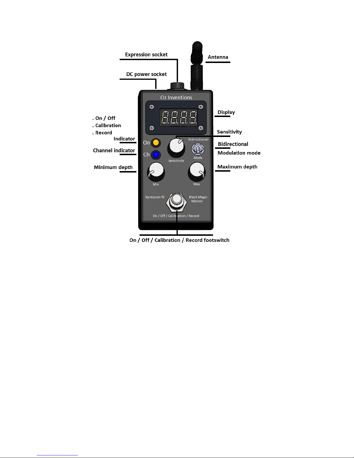
Figure 2 Top panel controls
Expression jack – Tip, Ring, Sleeve type 6.35mm (¼” )socket
Antenna – 2.4GHz vertical omni-directional 110mm antenna
Display – modulation mode; Sweep position; Menu text; mode indicators
Bidirectional switch –Positive modulation output, or Negative and positive modulation output
Mode switch – Tilt, rotation, Velocity, Force, Guitar-hand, Automatic, Playback
Minimum Depth – sets the minimum modulation position (heel down)
Maximum Depth - sets the maximum modulation position (toe down)
ON/OFF/calibration/record footswitch- Turns modulation on & off; Calibrates the the beginning and
ending modulation sweep points; Arms recording and stops recording.
Channel indicator – Three channels within the 2.4GHz spectrum; Identified as Red, Green and Blue
ON/OFF/calibration/record indicator – Yellow
Illuminated = Modulation ON; Extinguished = Modulation OFF; Fast flashing = calibrating; Brief slow
flashing = Record armed; Continuous slow flashing = Recording in progress.
Sensitivity – sets response time, stability, playback time and other parameters dependent on the
chosen modulation mode
DC power jack –2.1mm; 9 – 12V; 150mA; Negative centre
Page 11
11
© Oz inventions
Version 1.8
Connecting
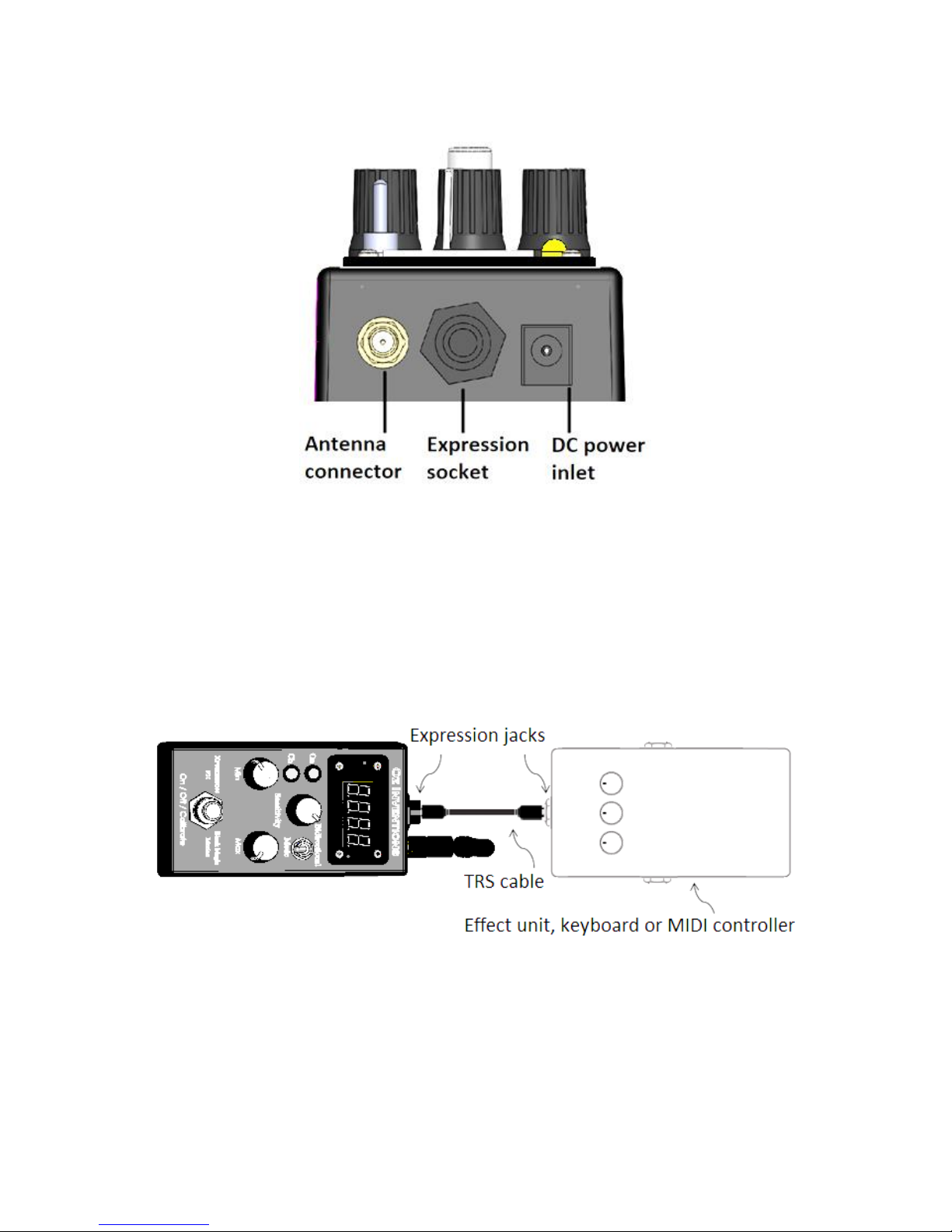
The rear of the device provides access to the expression, antenna and DC power sockets.
Figure 3 Rear panel connections
Connecting the expression jack
Connect the expression socket of the receiver to the expression socket of an effects unit, keyboard or MIDI
controller, using a TRS cable. Regardless of whether TRS, RTS, TS, RS or CV polarity is chosen, a TRS cable is
required. The wiring configuration of the TRS cable is tip to tip; ring to ring; and shield to shield.
A TS (mono) cable can be used for switching only, if the effects unit/keyboard/MIDI controller provides that
functionality and is compatible See Using the modulator as a footswitch pg 50
Figure 4 – Connecting the expression jack
The plug/socket connection is firm and should click as it is made. The plug should be pushed in until all of the
silver plating is inside the socket.
Page 12
12
© Oz inventions
Version 1.8
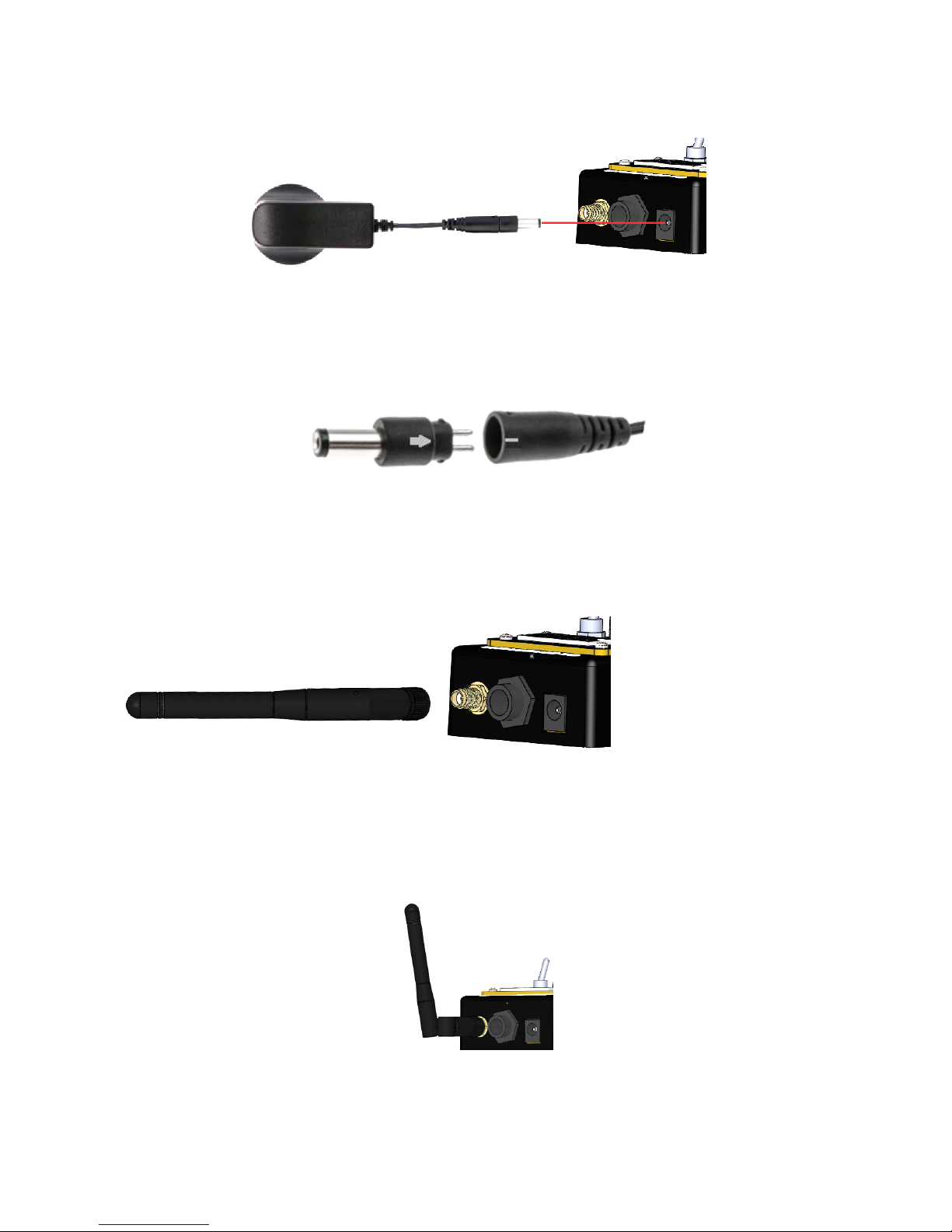
Connecting the DC power adapter
Push the DC power supply plug into the DC power inlet.
Figure 5 – Push the DC power plug into the DC power inlet
The DC power plug is reversible. It is provided with the correct configuration. Should the polarity need to be
changed the arrow should point toward the negative (-) symbol. This provides the correct polarity (negative
tip) for the receiver-modulator.
Figure 6 – Correct polarity – Negative tip
Antenna
The antenna is packed straight. It is hinged and can be bent. Leave it straight when attaching.
Screw the antenna gently in a clockwise direction onto the antenna socket
Figure 7 – Screw the antenna in a clockwise direction
Best reception is found when the antenna is bent at a 90 degree angle (vertical). However, slanting the
antenna back a few degrees may have an insignificant impact on reception and has the advantage of being
more tolerant to accidental damage.
Figure 8 – Angle the antenna back slightly
Page 13
13
© Oz inventions
Version 1.8
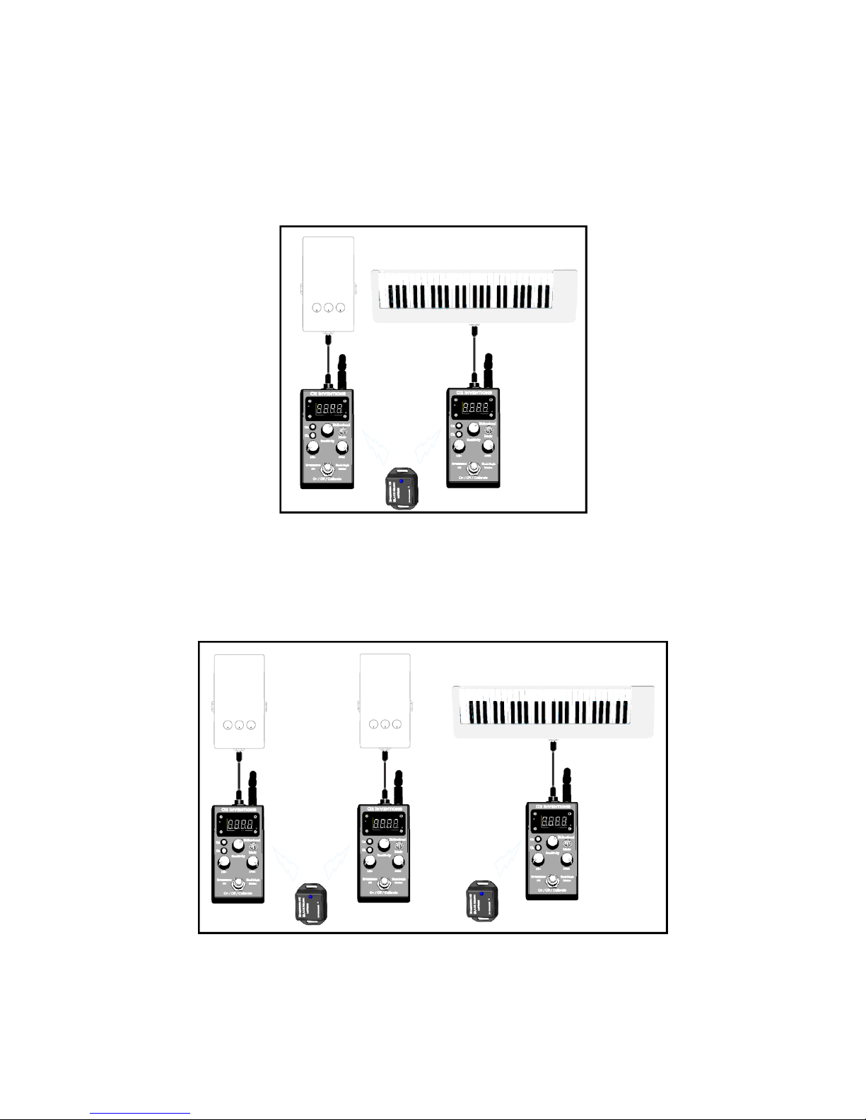
Connecting multiple receivers
Using multiple receivers provides the ability to control multiple units using different modulation modes. For
example one receiver can be set to respond to tilt whilst another receiver can be set to respond to rotation.
The picture below shows two receivers being controlled by one sensor-transmitter. Both receivers are set to
the same channel and can be set to the same or different modulation modes. There is no limit to the number
of receivers that can be used with a single sensor-transmitter.
Figure 9 – Connecting multiple units
Setting multiple sensor-transmitters and receivers to different channels is also possible and offers many
combinations and possibilities. The picture below shows two sensor-transmitters on different channels.
Sensors can be attached to anything that moves. E.g. guitar, arm, leg, drummer, dancer etc
Figure 10 -= Many possibilities
Page 14
14
© Oz inventions
Version 1.8
Main indicator lights
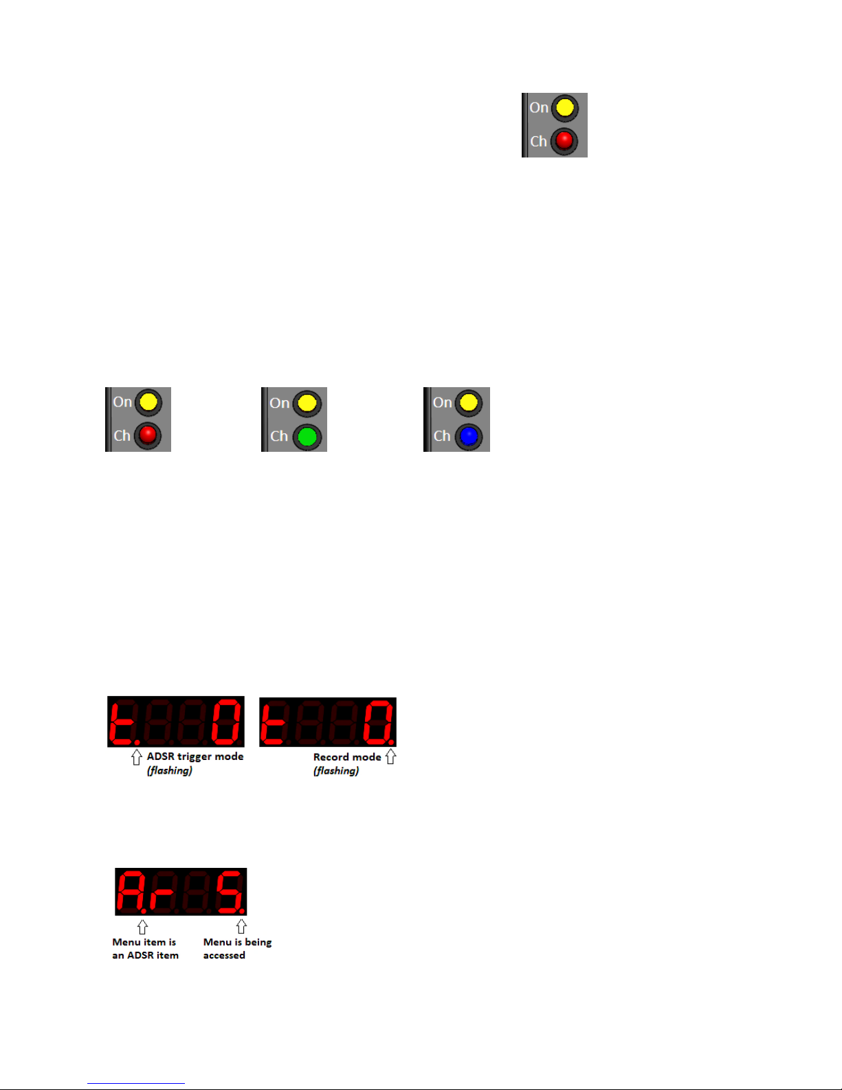
There are two main indicators and each provides multiple indications.
ON
The ON indicator shows when modulation is on or off. When illuminated, modulation is on.
The ON indicator also indicates when calibration is occurring in ‘Free’ mode, via flashing.
The ON indicator also indicates states of recording when in ‘Rec’ mode. The indicator flashes and then goes
steady when recording is armed. The indicator starts flashing again when recording has started and stops
flashing when recording is completed.
Ch
The Ch indicator shows which of the three RF channels is selected. Identified as Red, Green and Blue.
Figure 11 – Channel indicator lights
Three channels are provided to increase the systems capability by working with multiple sensor-transmitters
and multiple modulator-receivers, and also to avoid or limit electrical interference.
Minor indicator lights
There are two minor indicator lights and each provides unique indications in normal use mode and also
within the menus.
Indicator lights in normal use mode
In normal use mode the indicator lights signify ‘Record mode’ or ‘ADSR trigger mode’. The absence of lights
signifies ‘Free’ mode.
Indicator lights in menu mode
An illuminated dot under the last character, signifies that the menu is currently being accessed. An
illuminated dot under the first character signifies that the current menu item is an ADSR item.
Yellow
Red
Yellow
Green
Yellow
Blue
Yellow
Red
Page 15
15
© Oz inventions
Version 1.8
Controls
Modulation mode switch
The mode switch is a momentary toggle switch. It is toggled forward and then released. The mode switch
selects between modulation modes.
The modulation modes are tilt, quad tilt, rotation, velocity, Flick automatic and playback.
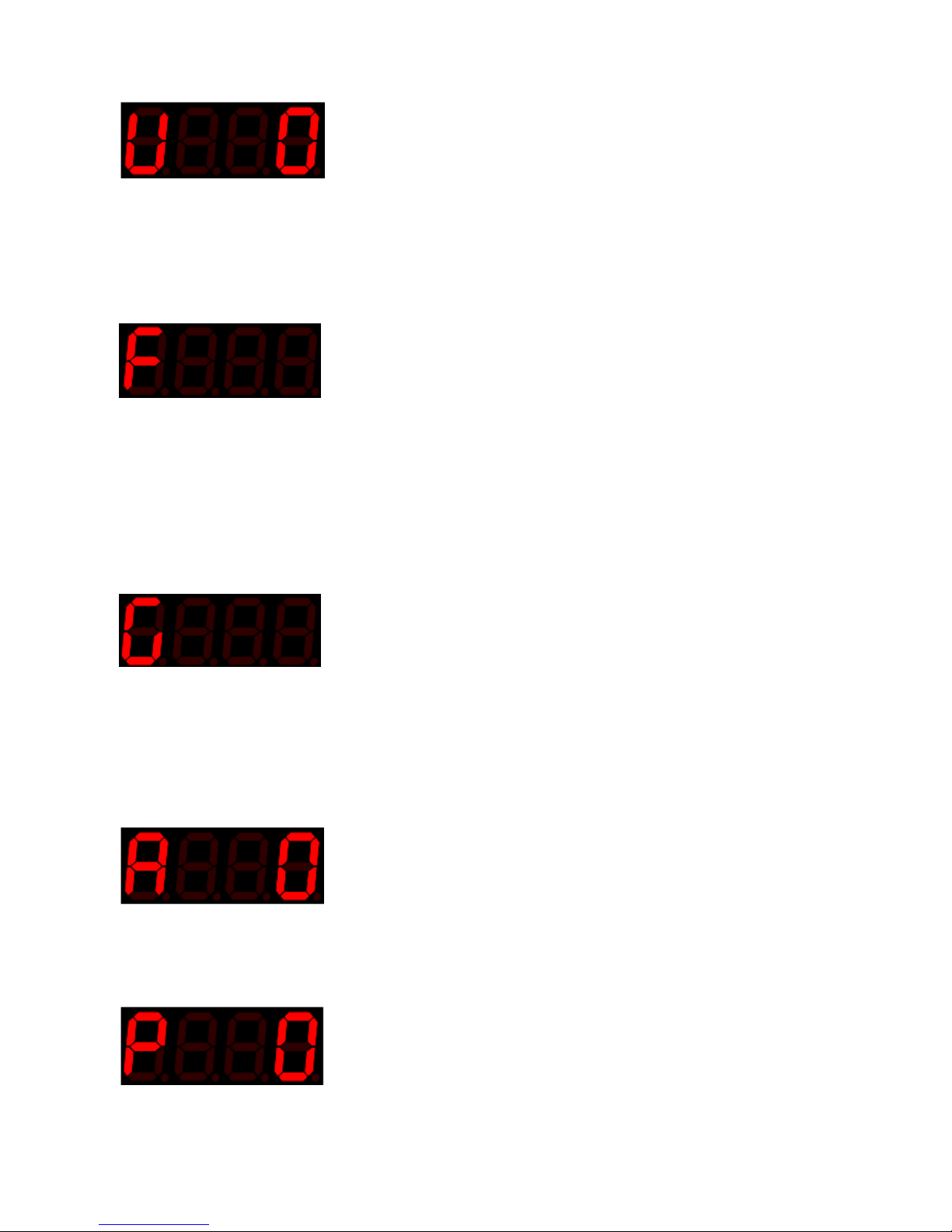
Tilt (t)
Default angle 0 – 90 degrees; Range 0 – 90 degrees;
Default orientation – Top; Range – Top, Bottom, Left, Right, Front & Rear
This mode is designed for tilting and rolling in a single direction or two directions if the bidirectional switch is
used. Calibration is usually required before use.
Quad tilt (q)
Default useable angle 0 – 90 degrees in four directions; Range 0 – 90 degrees in four directions; Default
orientation – Top; Range – Top, Bottom, Left, Right, Front Rear
This mode is designed for tilting and rolling in any direction. Calibration is usually required before use.
Rotation (r)
Default 0 – 90 degrees; Range 0 – 36000 degrees;
This mode is designed for rotational movement such as side to side swaying or swinging, as maybe done
when playing a guitar, dancing or other circular movement.
Calibration is usually required before use. See Rotation calibration process pg 30
The bidirectional switch allows a continuous circle
Page 16
16
© Oz inventions
Version 1.8
Velocity (v)
Range 0 – 127;
Default sensitivity to speed is dependent on the position of the sensitivity control. Higher (clockwise)
sensitivity requires less speed to reach the maximum depth.
This mode is designed for moving at different speeds. Faster speeds modulate more than slower speeds.
Flick (F)
Range 0 – 127;
This mode is designed for forces. Stronger forces modulate more than weaker forces. It is designed as a
trigger for the ADSR envelope but may also be used with very rapid movements.
The sensitivity adjustment controls how much force is required to reach the maximum depth as set by the
maximum depth control.
Guitar-hand(G)
Default 0 – 90 degrees; Range 0 – 720 degrees;
This mode is designed for the specific rotation of a guitar or keyboarding hand.
Calibration is usually required before use. See Rotation and Guitar-hand mode calibration process pg 35
As with ‘Rotation’ mode, the bidirectional switch enables a continuous circle.
Automatic ADSR (A)
Plays the ADSR envelope as set within the ADSR menu
See Understanding ADSR, Automatic ADSR mode and ADSR trigger mode
Playback recorded ADSR (P)
Plays the recorded ADSR envelope as recorded in record mode. See Understanding recording pg 37
Page 17
17
© Oz inventions
Version 1.8
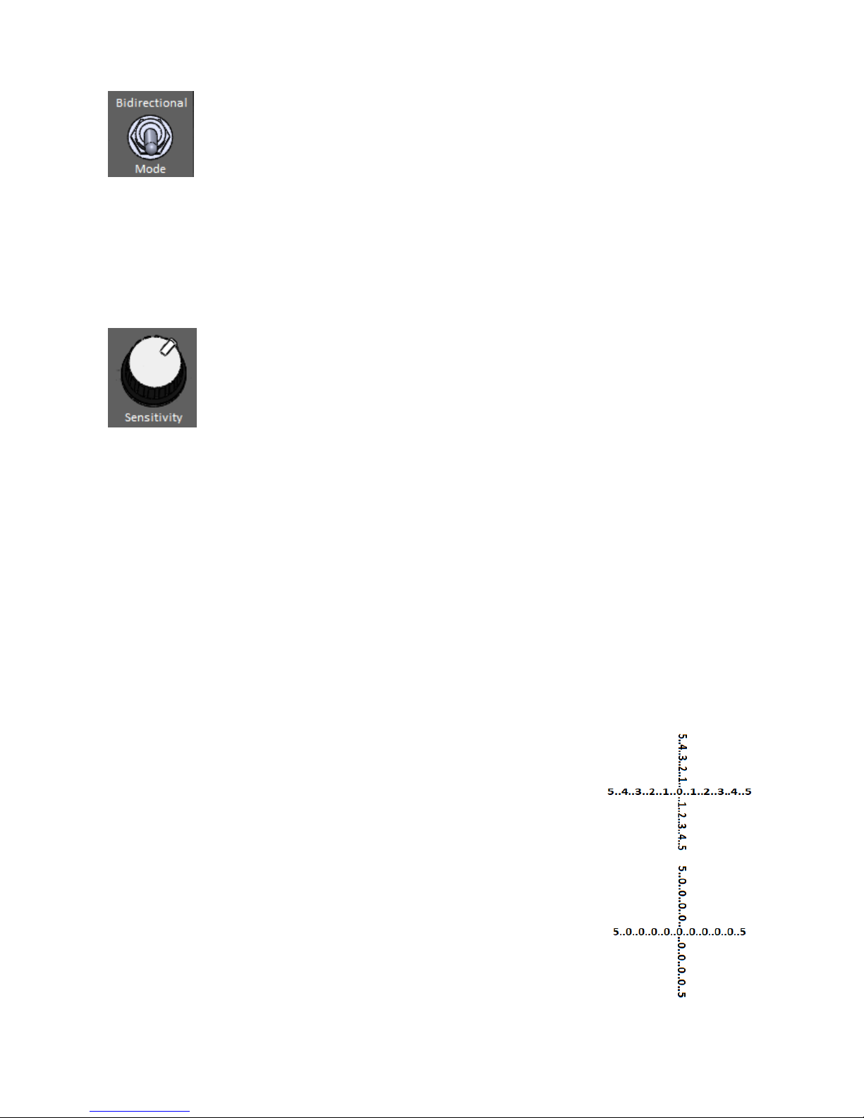
Bidirectional switch
The bidirectional switch is a permanent toggle switch. It is actuated by pushing it backward. It enables
modulation output in two directions. Modulating output will normally decrease from 127 to 0 and there will
be no further change should the sensor continue below the 0 point. With bi-directional selected, the
modulating output will continue to be present in the negative direction. -127 - 0 – 127 . In rotation and guithand mode the bidirectional switch enables a continuous sweep.
Sensitivity control (0 – 99)
The sensitivity control has different functions depending on which modulation mode is being used.
Tilt mode
The sensitivity control adjusts how quickly the modulator responds to received data from a sensor, and how
stable the modulated output is. The control is a compromise between response and stability. Great stability
comes with a slow response time. Quick response times are less stable. Either condition is not a hindrance,
but rather can be used to good effect. For example quick response and low stability enables quick
movements to produce warbling effects, whilst slow response and high stability enables robust player
movements so that modulation only occurs at specific points. A slow response can also be used to provide a
delay which gives a pad type string effect as modulation slowly increases and decreases.
Knowing the exact position of the sensitivity control is not always needed, however its level is briefly flashed
on the screen whenever it is moved. Fully anti-clockwise = 0. Fully clockwise = 99.
Quad tilt mode
The sensitivity control adjusts the point where the modulated output effectively
has a value of zero. With the control at ‘0’ (fully anti-clockwise) the zero point is
where it is expected to be, directly after or before ‘1’, depending on which
direction the 4-way mode is tilting.
As the sensitivity control is moved clockwise higher values also begin to have a
value of zero. This gives a point of rest for the user because without this space
there would always be some modulation as the user quickly crosses over the zero
point.
The sensitivity control in quad tilt mode also enables effective retriggering of the
ADSR envelope. The zero point is needed for retriggering and is difficult to locate
when there is only a small zero point window available.
Page 18

18
© Oz inventions
Version 1.8
Velocity mode
The sensitivity control adjusts how much velocity is required to reach maximum modulating output (127).
Low values (anti-clockwise) require more velocity to reach maximum, whilst high values increase the
sensitivity, making lower speeds reach the maximum modulating output.
Playback mode
The sensitivity control is used as a trim control in playback mode to remove possible uneven timing toward
the end of the recording. See ‘Understanding recording’ pg 37
The sensitivity control has many functions and so it is important to have it in the correct position for each
mode. If it is in the wrong position, the result can be no modulating output. If at any time modulation is
not working as expected, check the sensitivity control, and also the min and max depth controls.
Min depth (0 – 127)
The minimum depth control limits the modulating output by preventing modulation falling below a preset
level. For example, when minimum depth is set to 25, modulation cannot go lower than 25. For example, if
the chosen effect parameter to be modulated is ‘volume’ with a range from no volume at 0, to maximum
volume at 127, setting the minimum depth control to 25 will prevent the volume from reaching zero. In
relation to a traditional expression pedal, the minimum depth control can be likened to the heel down
position.
Knowing the exact position of the minimum depth control is not always needed, however its level is briefly
flashed on the screen whenever it is moved. Fully anti-clockwise = 0. Fully clockwise = 127.
The minimum depth control also functions as the menu item indexer. The control does not function as a
depth control when a menu is accessed. However, its value is retained by the system when inside a menu.
When a menu is exited the control should be returned to the position it was in before menu entry.
It is important to have the minimum depth control in the correct position for the result you are trying to
obtain. If it is in the wrong position, the result can be no modulating output. Whenever the menu is
exited, be sure to correctly place the minimum depth control. If at any time modulation is not working as
expected, check the minimum depth control, and also the maximum depth control and the sensitivity
control.
Max depth
The maximum depth control limits the modulating output by preventing modulation rising above a preset
level. For example, when maximum depth is set to 90, modulation cannot go higher than 90. For example, if
the chosen effect parameter to be modulated is ‘volume’ with a range from no volume at 0, to maximum
Page 19

19
© Oz inventions
Version 1.8
volume at 127, setting the maximum depth control to 90 will prevent ‘maximum volume’ being reached. In
relation to a traditional expression pedal, the maximum depth control can be likened to the toe down
position.
Knowing the exact position of the maximum depth control is not always needed, however its level is briefly
flashed on the screen whenever it is moved. Fully anti-clockwise is 0, fully clockwise is 127.
The maximum depth control also functions as the menu item parameter indexer. The control does not
function as a depth control when a menu is accessed. However, its depth value is retained by the system
whilst in the menu. When the menu is exited the control should be returned to the position it was in before
menu entry.
It is important to have the maximum depth control in the correct position for the result you are trying to
obtain. If it is in the wrong position, the result can be no modulating output. Whenever a menu is exited,
be sure to correctly place the maximum depth control. If at any time modulation is not working as
expected, check the maximum depth control, and also the minimum depth control and the sensitivity
control.
Page 20
20
© Oz inventions
Version 1.8
Display
In normal use mode, the display shows the modulation output and the modulation mode. The display also
shows menu information and has indicator lights to signify a menu is currently being accessed, and also
indicator lights outside of a menu to show when ADSR trigger, and Record mode are selected.
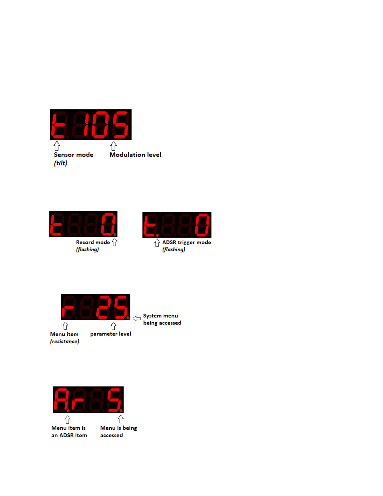
Display in normal use mode
In normal use mode, the display shows the currently chosen modulation mode and the modulation level of
that mode.
Indicator lights in normal use mode
In normal use mode the indicator lights signify record mode or ADSR trigger mode. The absence of lights
signifies ‘Free’ mode.
Display in menu mode
In Menu mode, the display shows the currently selected menu item and its current parameter level. An
illuminated dot under the last character distinguishes between menu access and normal use mode.
Indicator lights in menu mode
An illuminated dot under the last character, signifies that the menu is currently being accessed. An additional
illuminated dot under the first character signifies that the current menu item is an ADSR item.
Page 21
21
© Oz inventions
Version 1.8
Menu
There are two menus and a preset select option.
1. The system menu holds system items and ADSR items–
System items –Resistance, polarity, receiving channel, remote on/off, record trigger level,
reverse sweep direction, record time, linear/log sweep, and selects Free mode, ADSR trigger
mode & Record mode.
ADSR items – Changes ADSR settings - attack rate, decay rate, sustain level, sustain time, release
rate and trigger modes.
2. The step size menu holds step size items. Variable step sizes from 1 – 127.
3. There are 10 available presets. Unless changed, each preset holds the same default information.
There is also a reset option accessed during power on that returns the unit to default settings See pg 29
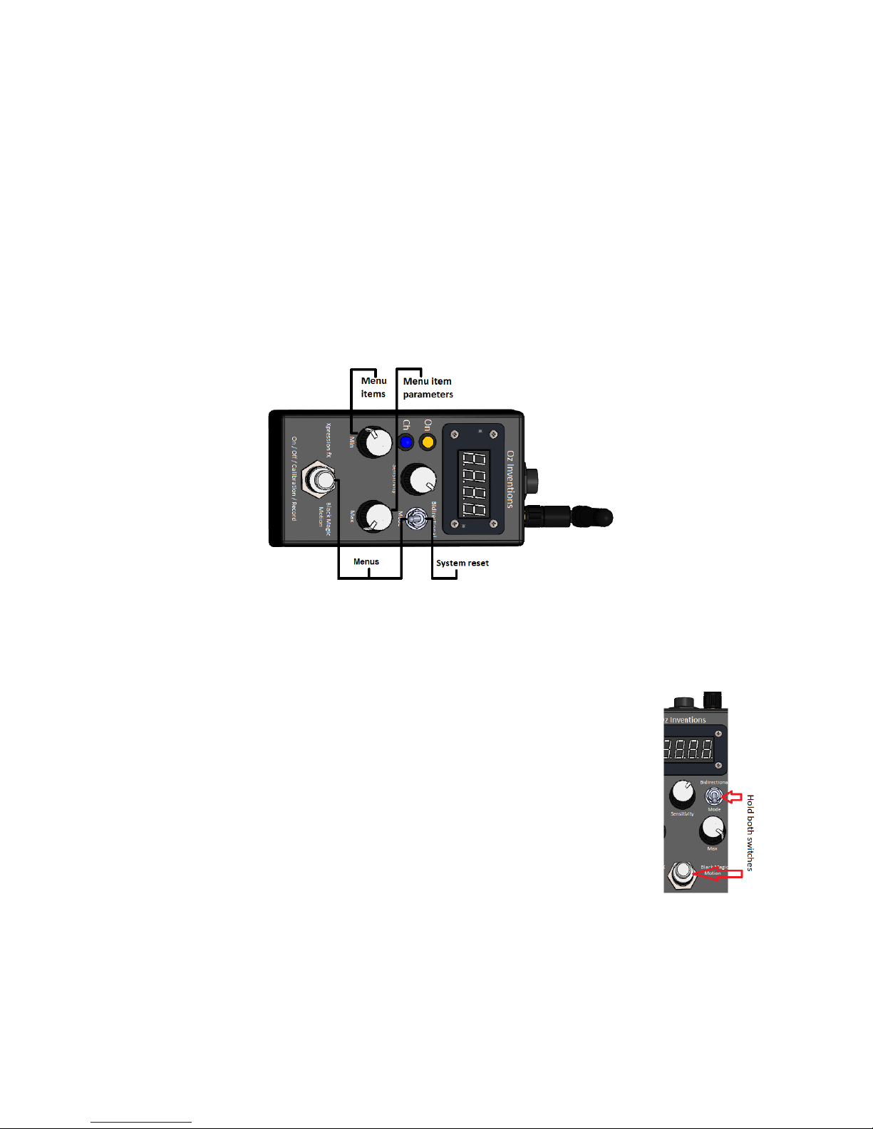
Menu access and control
Figure 12 – Menu Access and control
The system menu is accessed by first pressing and holding the on / off / calibration / record switch
and then pulling forward the modulation mode toggle switch. Both switches must be held together,
with the on/off/calibration/recording switch being held first.
The ‘Step size’ menu is accessed by first pulling forward and holding the
modulation mode toggle switch and then pressing the
on/off/calibration/recording switch. Both switches must be held together, with
the toggle switch being held first.
Once inside a menu the minimum depth control moves through the menu items
and the maximum depth control changes the parameters of the currently
selected menu item. Exiting the menu is done in the same way as entry
.
The presets are access by rotating the maximum depth control fully counter
clockwise (0) and rotating the minimum depth control fully clockwise (127). The presets can then be
changed by pulling forward the modulation mode toggle switch. To exit preset selection, change the
minimum or maximum depth control to any position.
Page 22
22
© Oz inventions
Version 1.8
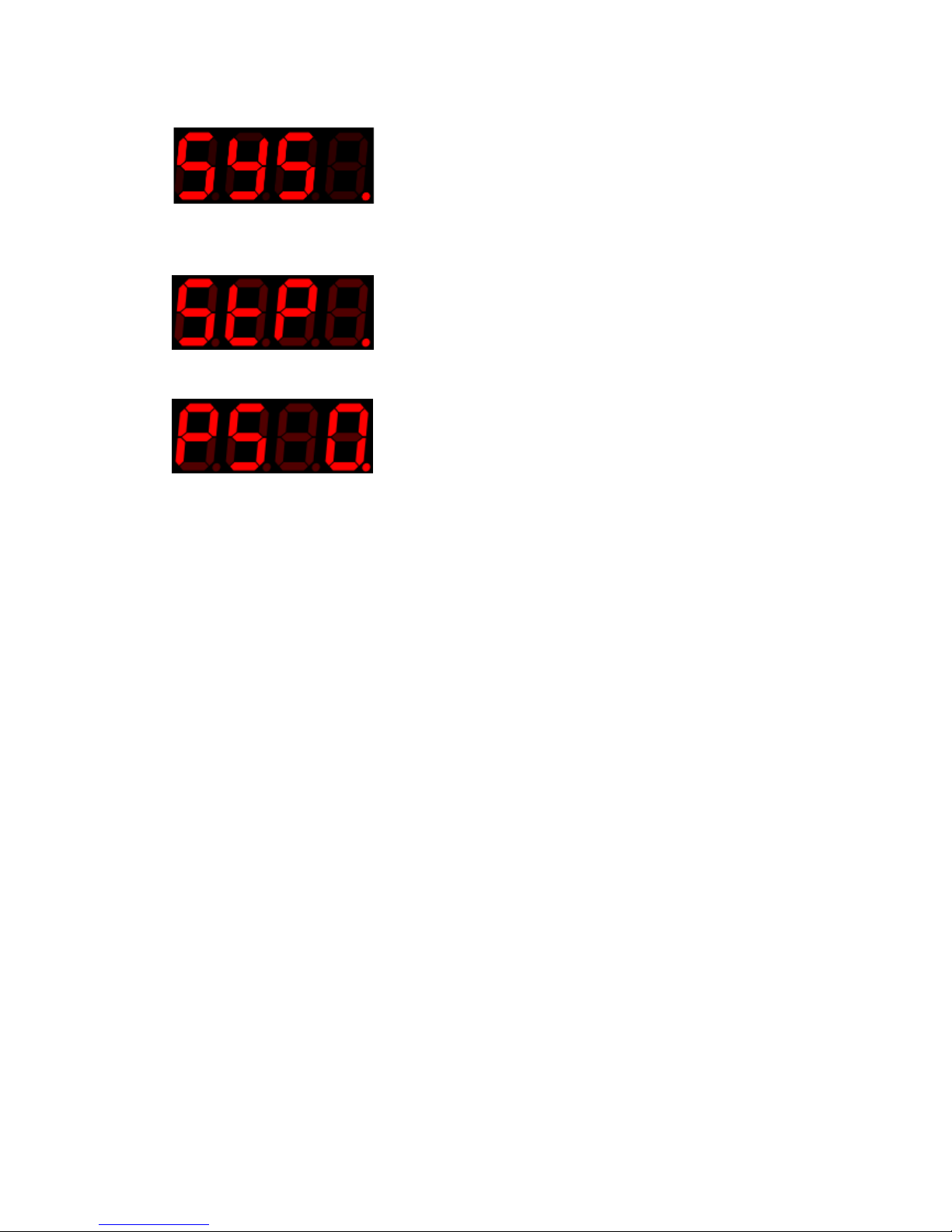
‘SyS’ appears on the display briefly when the system menu is entered. The display then shows the
first menu item
‘Stp’ appears on the display briefly when the ‘Step size’ menu is entered. The display then shnows
the first menu item.
‘PS appears on the display when ‘Preset’ selection is entered. ‘
A small illuminated dot is permanently on under the last character on the display to signify that a
menu has been entered.
A small illuminated dot is also permanently on under the first character of the ADSR settings only, to
distinguish between the ADSR settings and the other settings.
Exit from a menu is done in the same way as entry.
The individual items of a menu are indexed via the minimum depth control.
The individual menu item parameters are modified by the maximum depth control.
After meu exit, it is important to remember that these controls may need to be returned to the
position they were in before entry, depending on what is required.
Calibration is not possible when in ADSR or Record mode. Any calibration should be carried out
before entering these modes.
The hard ON/OFF switch and soft ON/OFF control, functions as normal when in the system menu
The minimum and maximum depth controls do not function as depth controls when in the menu.
However, their values at the time of menu entry are retained whilst in the menu.
After menu exit the min and max depth controls will take on the values relevant to their current
position and so,
After menu exit, It is important to return the depth controls to the position they were in before
menu entry
System reset
System reset is actuated by holding the modulation mode switch forward, whilst applying power, and then
releasing the switch.
Page 23
23
© Oz inventions
Version 1.8
System menu items
The system items in the menu enable adjustment of system settings. Some of these settings may only need
to be set once, or rarely.
Soft power On/Off
Default – 0; range 0 – 99;
Modulation can be turned ON & OFF via the modulation footswitch, but can also be turn ON & OFF remotely
if ‘Soft Power On/Off’ is set. A setting of ‘0’ disables ‘Soft Power On/Off’ and then only the footswitch can be
used to turn modulation ON & OFF. Settings 1 – 99 enable Soft Power On/Off with a range of sensitivities. A
setting of 1 is very sensitive and so only a light movement of the sensor is required to turn modulation On &
Off. A setting of 99 is very insensitive and so a very forceful movement is required to turn modulation On &
Off. If used, generally the setting should be higher than that required to create the modulation, else
modulation will turn On & Off whilst activating modulation via tilting or rotating etc. However, it can also be
used to good effect to have it set low. Experimenting will show the way.
The modulation on/off footswitch still functions when ‘Soft Power On/Off’ is enabled.
Free/AtrG/Record (Free / AtrG / rEC)
Default – Free; Range - Free, AtrG & Record
Free
Modulation output is based directly on sensor motion. The range is 0 – 127 and can be modified via the
minimum and maximum depth controls. For example, with the minimum depth control set at minimum and
the maximum depth control set at maximum, the modulation output will range from 0 – 127. Reducing the
maximum control will reduce the modulating output from 127. Increasing the minimum control will increase
the beginning modulation above 0.
AtrG (ADSR trigger mode)
The ADSR envelope will be triggered on and off by the modulating output, as per the ADSR trigger settings in
the menu.
Page 24
24
© Oz inventions
Version 1.8
Rec (Record)
The device will record the modulation output for a duration between 0 to 1000 seconds dependent on the
‘Recording Time’ set in the menu. The recording can be heard by selecting playblack (‘P’) with the
modulation mode switch. The recording will play back continuously and can be trimmed using the trim
(sensitivity) control. The recorded waveform cannot be saved. See Understanding recording pg 37
Resistance (r)
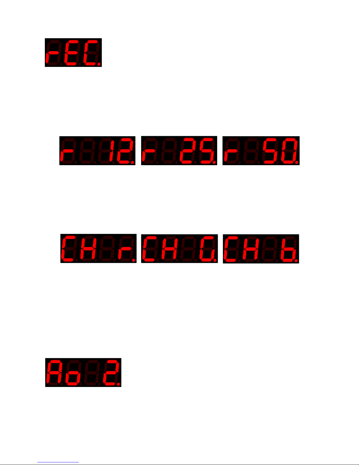
Default 12; Range 12, 25 and 50.
The device has three electrical resistances – 12Kohms; 25Kohms; 50Kohms.
Most effect units/keyboards/MIDI controllers, will function with any of these resistances. However, some
devices have specific requirements that must be adhered to for correct functioning. Refer to the effect
unit/keyboard/MIDI controller manual for specific requirements.
Channel (Ch)
Default red; Range – red, green & blue
The device has three receiving channels that correspond to the three transmitting channels from the sensortransmitter. The three channels are called Red, green and blue. The sensor-transmitter and the modulatorreceiver must be set to the same channel or there will be no motion activated modulation. However, the
modulator can still be used in standalone ADSR mode, or to play back a recording, regardless of the
availability of a sensor-transmitter. As the sensitivity control is moved the three channels can be selected. If
no sensor-transmitter is available the relevant indicator will briefly illuminate before extinguishing. If a
sensor-transmitter is available the relevant LED will remain lit.
Automatic cutoff
Default – 2 seconds; Range – 0 – 99 seconds
The automatic cut-off parameter determines how long after transmission ceases, the modulating output will
reduce to zero. A setting of ‘0’ has no cut-off.
Page 25
25
© Oz inventions
Version 1.8
The setting applies to the current modulation output and not the channel indicator. So, regardless of the
setting, the channel indicator will immediately extinguish as soon as reception is lost. After the set time has
elapsed the modulation output will be reduced to zero. The indicator light and modulation level will be
reinstated as soon as reception returns.
This setting may be needed if the parameter being modulated would present an unwanted audible noise if
left at its maximum setting, such as high volume or a grating tone.
This setting does not apply in automatic ADSR mode, or when playing back a recorded motion waveform.
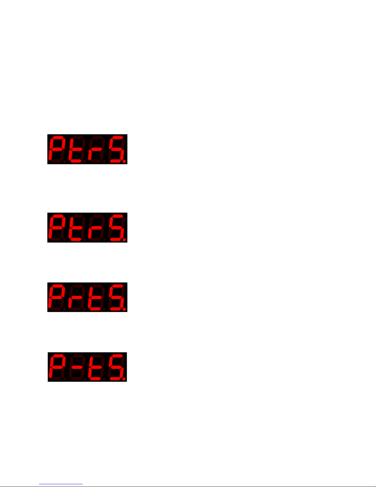
Polarity (P) (and foot switch and control voltage)
Default – TRS; Range TRS, RTS, TS, RS, CV
Many effects units/ keyboards/MIDI controllers use the TRS setting. However, many do not. . If this setting is
not set correctly the results can vary from no modulation to intermittent modulation. Refer to the effect
unit/keyboard/MIDI controller manual for specific requirements.
TRS
Tip, Ring, Sleeve. A constant voltage is applied to the ring and sleeve from the effect unit/keyboard/MIDI
controller. A varying voltage returns from the tip.
RTS
Ring, Tip, Sleeve. A constant voltage is applied to the tip and sleeve from the effect unit/keyboard/MIDI
controller. A varying voltage returns from the ring.
TS
Tip, Sleeve. The ring is disconnected. A varying voltage comes through the tip. Depending on the effects
unit/keyboard/MIDI controller, TS polarity may enable the modulator to function as a foot switch
Page 26
26
© Oz inventions
Version 1.8
RS
Ring sleeve. The tip is disconnected. This polarity can be used to simulate some footswitches.
CV
Control Voltage. The ring is disconnected. A varying voltage is generated by this device and returns through
the tip. The voltage is 0 – 5 volts DC. This is suitable for many CV devices. Some devices may require 10
volts, and so this modulator will have a limited range, though still a significant effect with 10 volt
synthesizers.
*Warning – Supplying a voltage to an incompatible external device can damage the modulator and the
incompatible device. CV mode is designed for connection to devices such as analog synthesizers that
require a varying 0 – 5v input. Current is limited to 2 milli-amperes. Ensure the other devices instruction
manual and/or the manufacturer is consulted before connecting the modulator to another device.
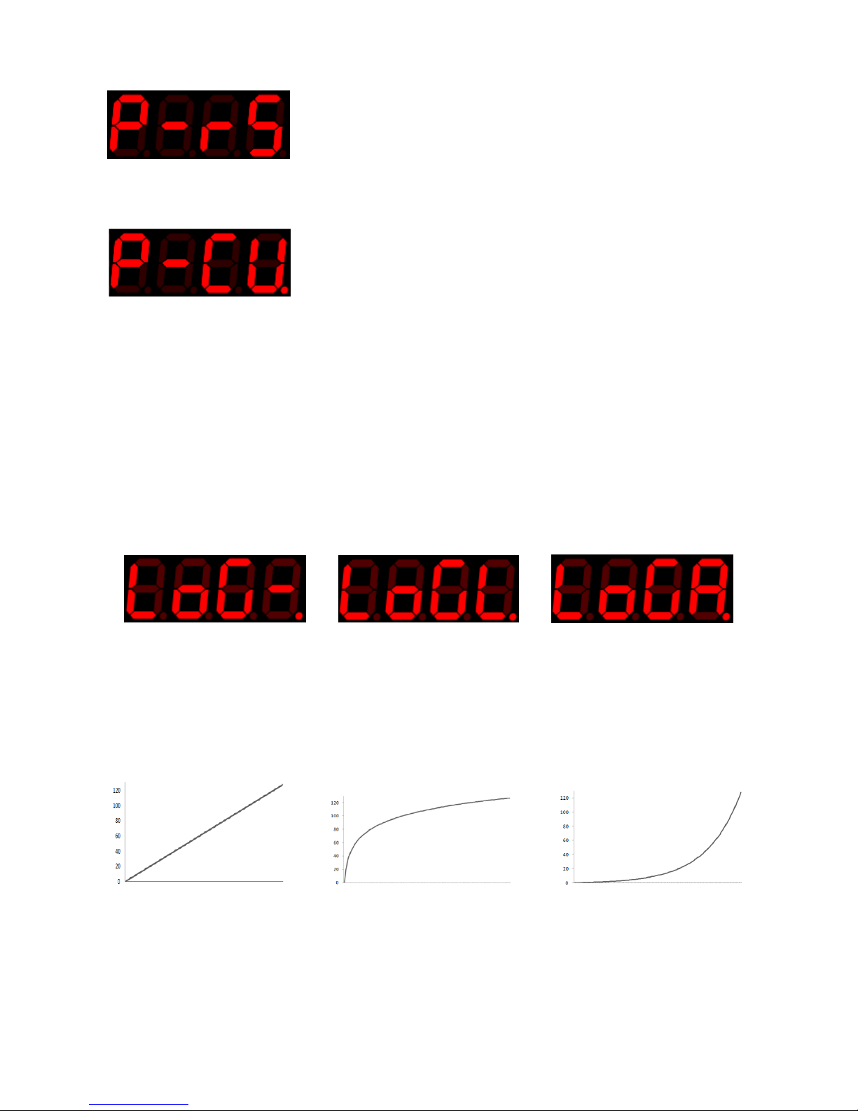
Linear / Logarithmic / Anti-Logarithmic scale
Default Linear; Range – Linear (LoG-); Logarithmic (LoGL); Anti-logarithmic (LoGA)
This sets how evenly the output rises.
Linear gives an even rise
Log gives an initial fast rise that slows down as it approaches the end
Anti-log gives an initial slow rise that speeds up as it approaches the end
Linear Logarithmic Anti-Logarithmic (Inverse)
Page 27
27
© Oz inventions
Version 1.8
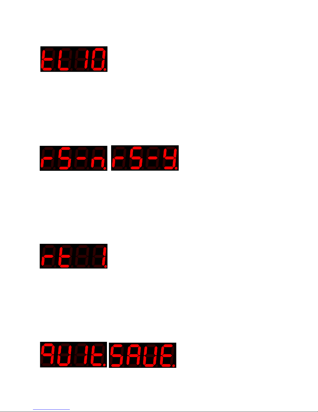
Record trigger level(tL)
Default 10; Range 0 – 127
Sets the level at which motion will activate recording. For example, if the record trigger level is set to 10, and
recording is armed, recording will start when the current modulation output moves 10 above or 10 below
the position recorded when the system was armed. The minimum depth control can also be used to trigger
recording.
See Understanding recording pg 37
Reverse sweep (rs)
Default – No; Range Yes & No
Changes the direction of sweep. For example if the current sweep changes a volume effect from lowest
volume to highest volume, reversing the sweep will change the sweep so the volume effect goes from
highest volume to lowest volume.
Reverse sweep can also be done by calibrating in the reverse direction, but it is provided in the menu for
easy access and so it can be applied to the ADSR envelope, and also to a recorded waveform.
Recording time (rt)
Default – 1; Range – 1 - 99
Changes the available recording time and changes the length of playback. There is a trade-off between
recording time and resolution or sample time, with longer recording times have lower playback resolution.
Quit / Save (quit / Save)
Default – quit; Range – quit & save
When the system menu is exited, the settings will be saved or not, dependant on this setting. The parameter
is always set to ‘quit’ when a menu is accessed. The parameter must be purposely changed to ‘Save’ even
after ‘Save’ has been selected previously.
Page 28

28
© Oz inventions
Version 1.8
Quit
The menu is exited and all settings, including calibration and system settings, remain as set by the user until
the device is powered off. When the device is powered on again, the settings revert to the previously saved,
or default settings.
Save
The menu is exited and all settings for all presets, including calibration, system settings and the current
modulation mode, are saved. When the device is powered off and on, the settings are retained.
Page 29
29
© Oz inventions
Version 1.8
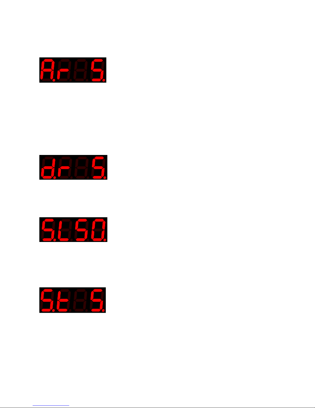
ADSR items
Attack Rate (Ar)
Default – 5; Range 1 – 99
With any modulated parameter, the attack rate sets how quickly the envelope rises from minimum to
maximum. It is adjustable from 1 – 99 in 10 millisecond increments with a scale setting of 1, and up to 1
second increments with a scale setting of 99. This provides a total stage time of 99 seconds.
As an example of controlling a volume parameter, the attack rate sets how long it takes to get from
minimum to maximum volume.
Decay Rate (dr)
Default – 5; Range 1 – 99
The decay rate sets how quickly the envelope decays to the sustain level
Sustain Level (SL)
Default – 50; Range 1 – 127;
The sustain level is the level the envelope remains at after the decay rate has finished. The sustain level
remains constant for a period set by the sustain time.
Sustain Time (St)
Default – 5; Range 1 – 99
The sustain time is the period of time between the decay rate finishing and the release rate starting.
Page 30
30
© Oz inventions
Version 1.8
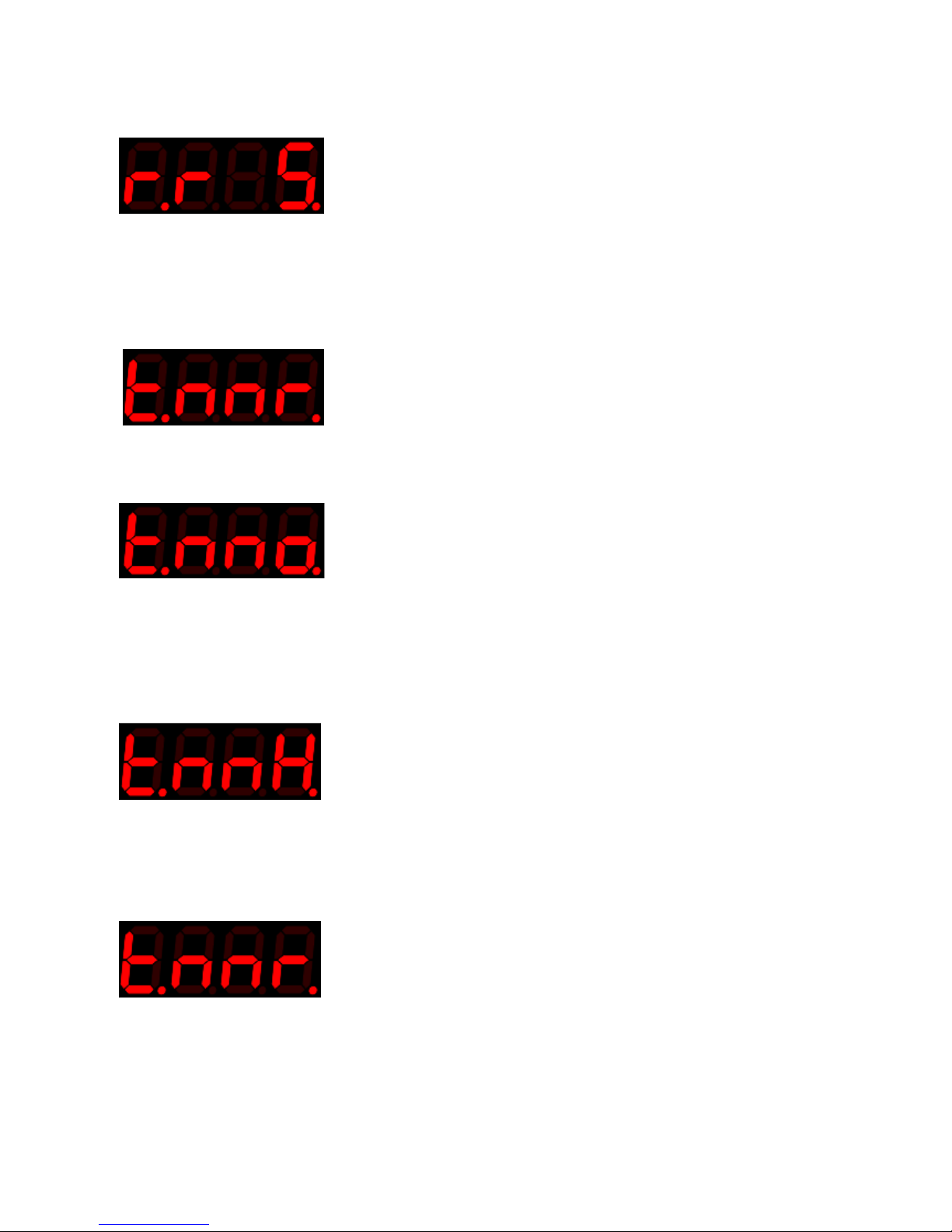
Release Rate (rr)
Default – 5; Range 1- 99
The release rate starts when the sustain time finishes, and sets how long the envelope takes to fall from the
sustain level to zero.
Trigger mode (tnn)
Default - Repeat; Range – Once (o), Hold (H), Repeat (r)
There are three trigger modes –
Once (t.nno.)
The ADSR envelope is triggered when modulating output reaching its maximum as set by the maximum
depth control ( 1 – 127). The envelope plays once when the maximum depth is reached. The envelope is
reset ready to be triggered again when the current modulation output reaches its minimum depth as set by
the minimum depth control.
Hold (tnnH)
The ADSR envelope is triggered by any modulation output reaching its maximum as set by the maximum
depth control (1 – 127). The envelope holds at the sustain stage until the current modulation output reaches
its minimum depth, as set by the minimum depth control.
Repeat (tnnr)
The ADSR envelope is triggered when the modulating output reaching its maximum as set by the maximum
depth control (1 – 127). The envelope plays continuously until the modulation output reaches the minimum
depth as set by the minimum depth control.
Page 31
31
© Oz inventions
Version 1.8
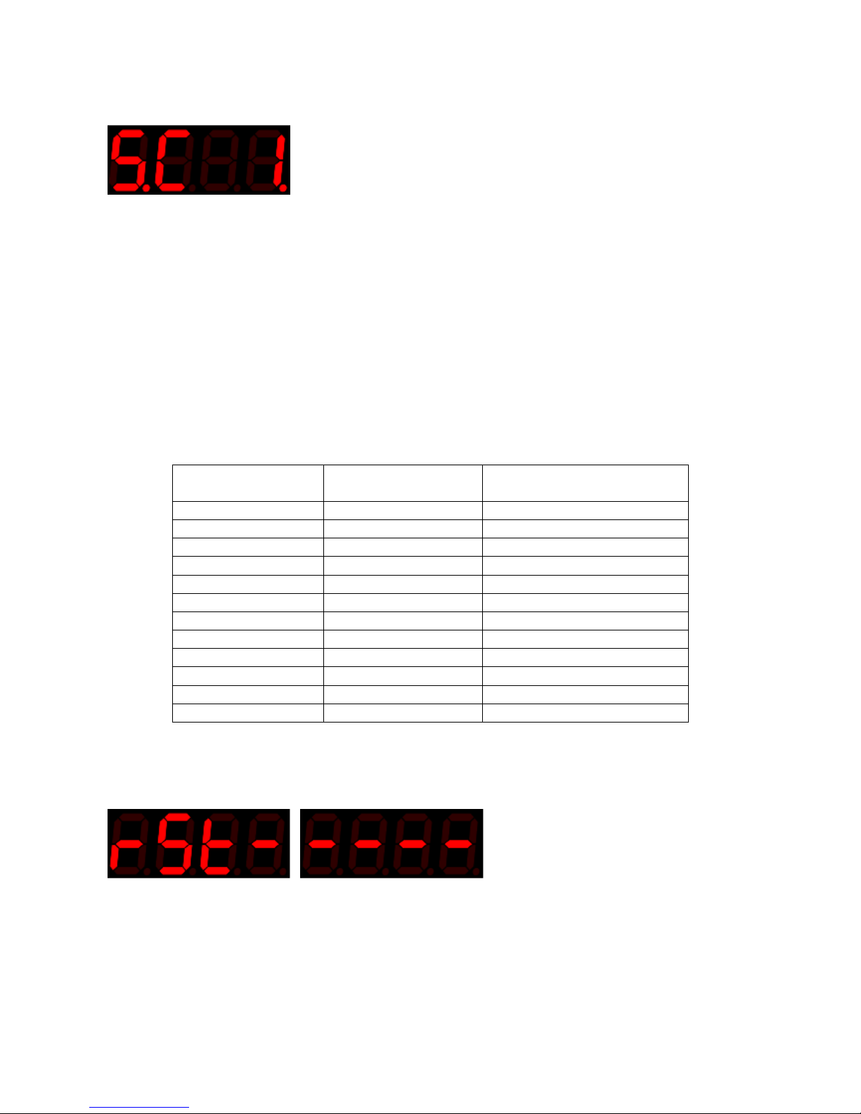
Scale (Sc)
Default 1; Range 1 – 99
Changes the overall envelope time by a factor of 1 - 99.
When scale is set to 1,
All rates are adjustable from 1 - 99 in 10 millisecond increments giving a total period of approximately 1
second for each stage. Settings below 5 can bring unwanted intermittent results.
When scale is set to 10
All rates are adjustable from 1 - 99 in 100 millisecond increments giving a total period of approximately 10
seconds for each stage.
When scale is set to 99
All rates are scalable from 1 - 99 in 1 second increments giving a total period of approximately 99 seconds for
each stage depending on the sustain level setting.
Scale
(value)
Increment size
(milliseconds)
Total length of ADSR envelope
(seconds)
1
10 1 2
20 2 3
30 3 4
40
4
5
50
5
. . .
10
100
10
20
200
20
30
300
30
. . .
90
900
90
100
1000 (1 second)
100
Table 1
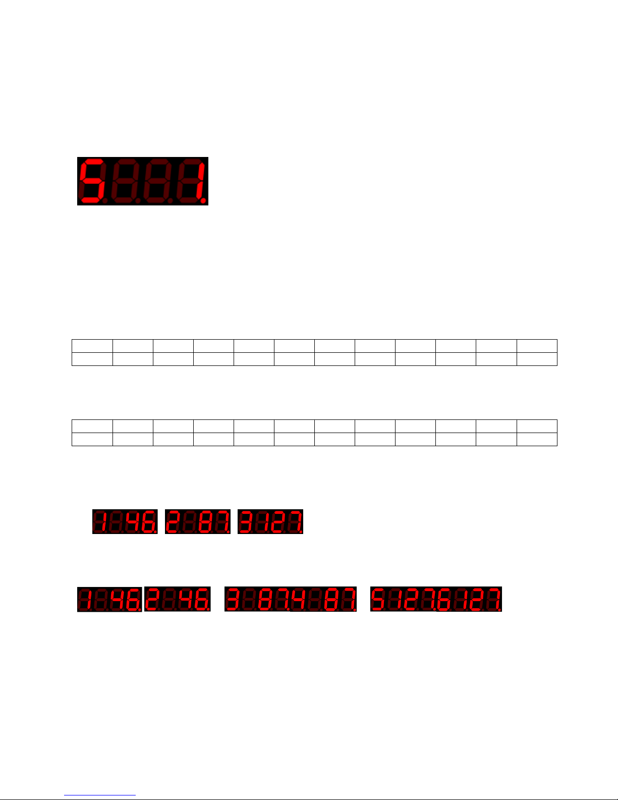
System reset
System reset restores the unit to its default settings. See Default settings pg 55
To reset the device
Reset the device by holding the modulation mode switch forward whilst powering on the device.
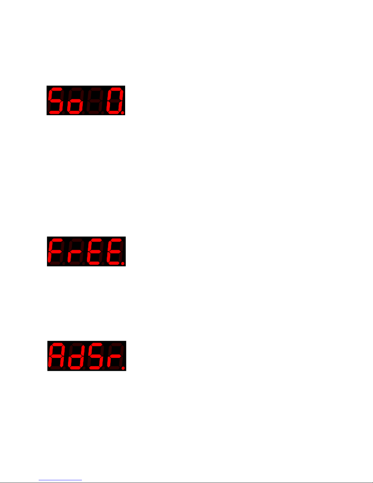
The display will show ‘rst-‘
Releasing the modulation mode switch will restore default settings and reboot the device
Alternatively, removing power whilst the switch is still held will retain the stored settings.
Page 32
32
© Oz inventions
Version 1.8
Step size menu items
The step size menu items enable how fine or coarse each step from 0 – 127 is and also enables individual
customised steps which when used for example with a pitch parameter may equate to semitone, tone, 3rd,
5th and/or octave steps.
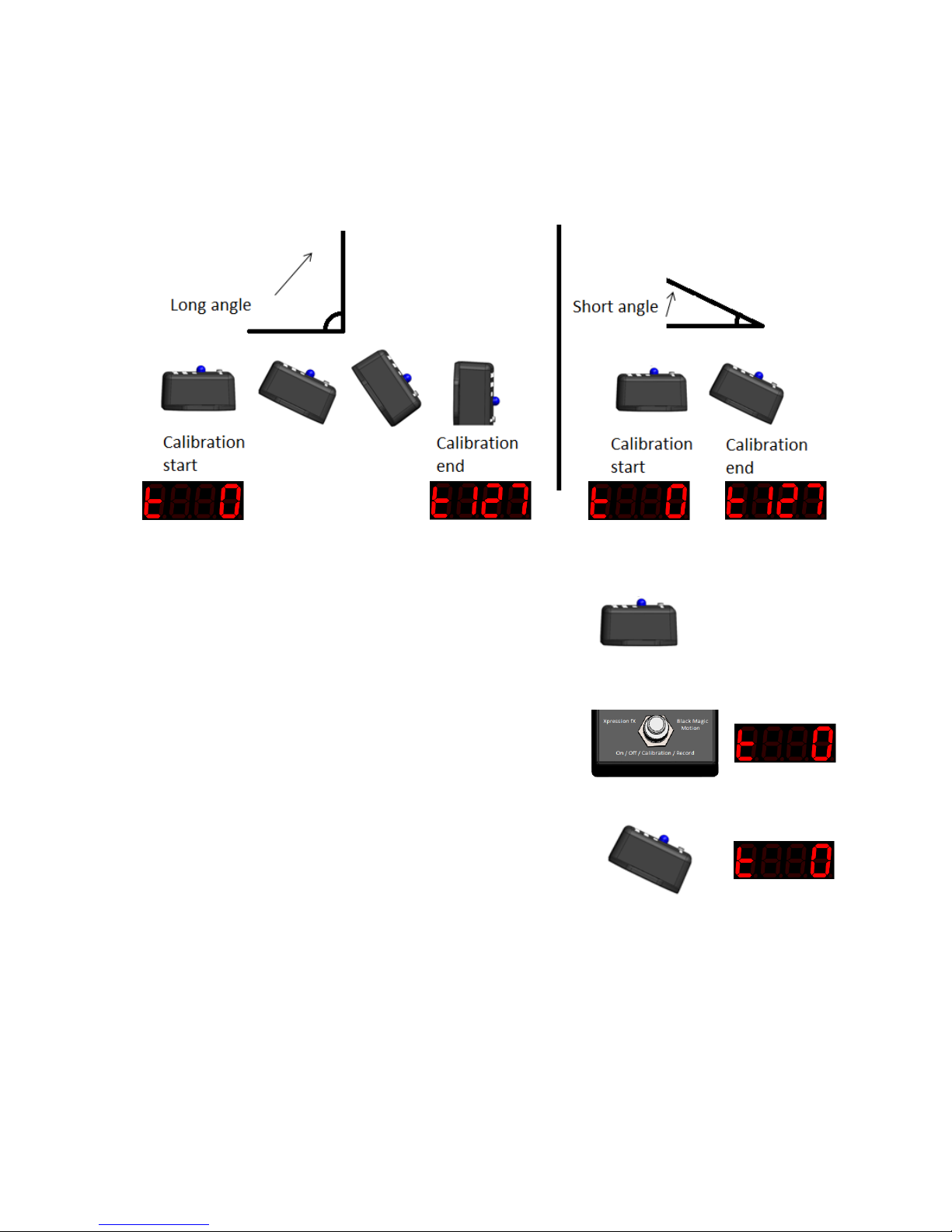
Step size (S)
Default – 1; Range 0 – 127
Modifies the size of each step as the modulating output progresses from 0 – 127. For example, when set to
10 the modulation output will follow this pattern – 0, 10, 20, 30 …. 110, 120, 127. This creates audible steps
in the modulation rather than a smooth progression as found when the step size is set to the default of ‘1’.
When the step size is set to ‘0, a step can be set to an exact amount rather than even multiples. In
this mode there are sixteen possible steps. The steps could for example be set to semitone steps.
The amount required for each step will vary depending on the effect unit, keyboard or MIDI
controller used. For example, the settings for semitone steps for Zoom® G1 are1 -
20
26
33
40
46
56
66
77
87
100
110
127
C# D D# E F
F# G G# A A# B C
1
Accuracy +/- 20 cents
Any step size can be used and any number of steps, up to sixteen, can be used. For example an arpeggio -
46
87
127 * E G C octave
*If required the minimum and maximum depth controls can limit how many steps are used.
A good ear for pitch or a chromatic tuner are required to set the steps accurately.
Each step is signified in the menu by a starting number, which is incremented by the minimum depth control
e.g
It can be useful to set the same value for multiple steps as this spreads the amount of tilt or rotation
required before a new step is selected. For example -
Calibrating over a larger angle also creates a wider spread.
Using step sizes in combination with an automatic or motion triggered ADSR envelope, and a pitch
parameter, creates an arpeggiator. In these modes the maximum and minimum depth control can
limit the steps heard. In these modes the depth controls display 1 – 16 for the 16 available steps,
rather than the usual 0 – 127.
The maximum depth control also adjusts the timing between the last rising and first falling step.
Page 33

33
© Oz inventions
Version 1.8
Preset selection
The preset selection enables changing between ten available presets numbered 0 - 9.
The presets are access by rotating the maximum depth control fully counter clockwise (0) and rotating the
minimum depth control fully clockwise (127). The presets can then be changed by pulling forward the
modulation mode toggle switch. To exit preset selection, change the minimum and maximum depth controls
to any other position.
Presets (PS)
Default – 0; Range 0 – 9;
Any changes made to the current preset are lost when a new preset is selected. Therefore, preset changes
should be saved when required by accessing the ‘Save’ menu item available in the ‘System’ or ‘Step size’
menus.
Selecting ‘Save’ in any menu will save all menu items from all menus, all calibration values and the current
modulation mode, to the currently selected preset.
Having presets enables quick changes. For example -
Presets enable quick changes between effect units/keyboards/MIDI controllers that have different
polarity and resistance settings
Presets enable quick changes between different customisable step sizes
Presets enable quick changes between different calibration settings
Upon first powering up the unit after manufacture, all presets will have the same default values (pg 55)
Page 34
34
© Oz inventions
Version 1.8
Calibration
General calibration process
Tilt, quad-tilt, rotation and guitar-hand modulation modes, need to be calibrated for best operation. The
calibration operation means to set the angle over which modulation occurs. The angle can be narrow or
wide. Modulation begins at zero at the start of calibration and finishes at 127 at the end of calibration.
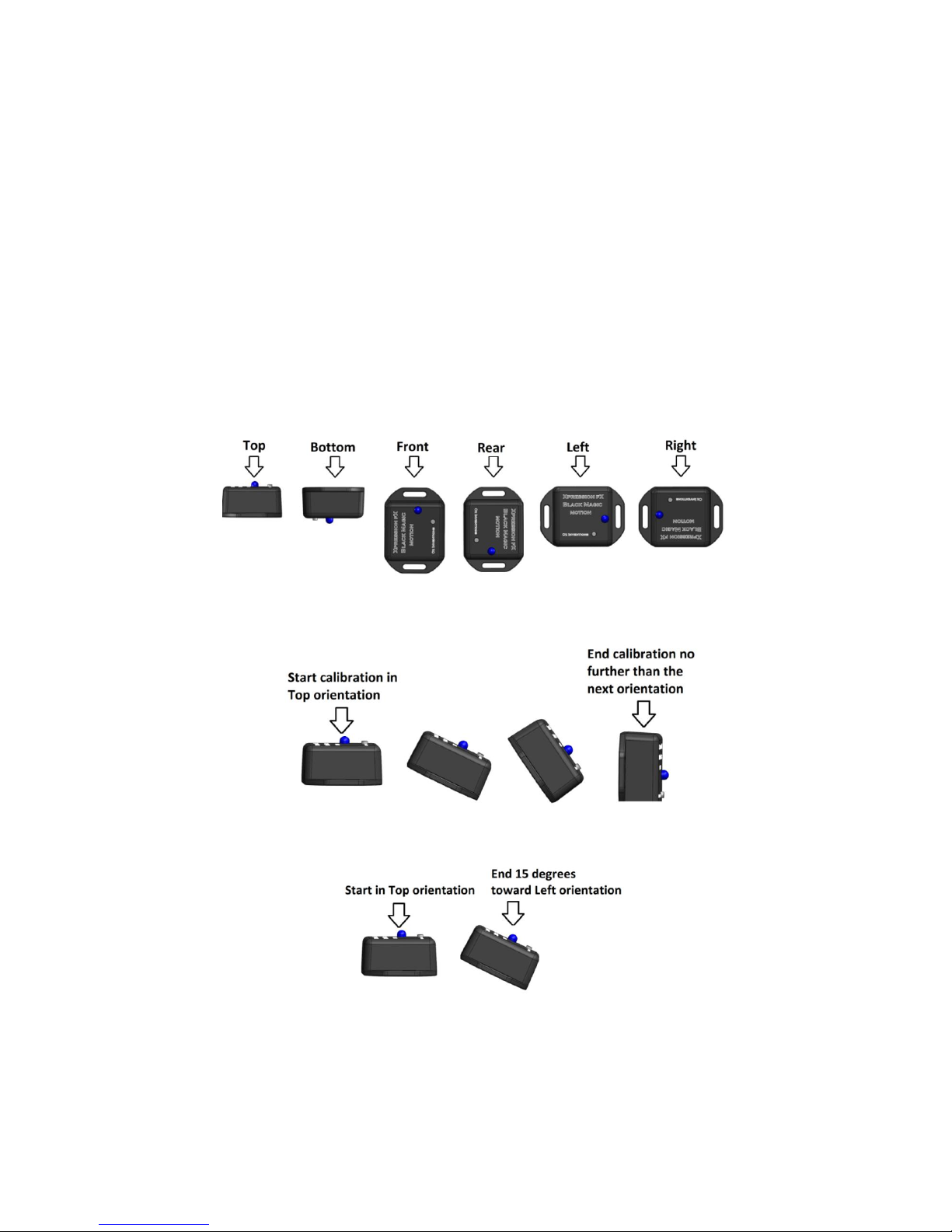
Figure 13 – Long and short angle Calibrations
Calibration steps
1. Hold the sensor-transmitter at the required starting position
2. Press and hold the on/off/calibration/record button on the
modulator-receiver. The ON indicator will start to flash,
signalling the start of the angle has been set and that a
modulation output of zero will be at that point.
3. Continue to hold the button and move the sensor-transmitter to
the finishing position
4. Release the button. The angle end has now been set and modulation will be at maximum at that
point.
Page 35

35
© Oz inventions
Version 1.8
Tilt and Quad tilt, calibration process
1. Hold the sensor-transmitter steady, on a vertical or horizontal plane with the ground in one of the
six best orientations. See Orientations
2. Hold the on/off/calibration/record button on the receiver-modulator
3. When the indicator starts to flash, the starting position has been set. Do not release the
on/off/calibration/record button
4. Tilt the sensor-transmitter no more than 90 degrees, in the required direction
5. Release the on/off/calibration/record button. The finish position has now been set.
6. The receiver is now calibrated for a 0 – 127 point sweep over the calibrated angle.
After calibration, tilting the sensor-transmitter further than the calibrated range will have no effect upon the
display or modulation, unless the start and finishing points are significantly past, after which the display will
become erratic.
The sensor-transmitter has six best starting orientations. Top; bottom; left; right; front and rear. If during
calibration the starting orientation is different from the finishing orientation, unexpected results can occur,
dependent on how far into the finishing orientation, calibration completes.
Best results are obtained by starting on a vertical or horizontal plane with the ground and tilting no further
than 90 degrees. However good results can often be obtained when started on an angle, depending on how
steep that angle is, and good results can be obtained when tilting further than 90 degrees.
Starting on a vertical or horizontal plane and tilting no further than 90 degrees is a failsafe method.
Before calibrating it is important to ensure the sensitivity control is adjusted at least half way. The sensitivity
control holds the signal tight or loose as required. If it is held too tight (anti-clockwise) during calibration the
modulation output may not change quickly enough, with the result being a very short calibration angle.
Rotation and Guitar-hand mode calibration process
1. Hold the sensor-transmitter steady, on a vertical or horizontal plane with the ground
2. Hold the on/off/calibration/record button on the receiver-modulator
3. When the indicator starts to flash, the starting position has been set. Do not release the
on/off/calibration/record button
4. Rotate the sensor-transmitter either clockwise or anti-clockwise.
5. Release the on/off/calibration/record button. The finish position has now been set.
6. The receiver is now calibrated for a 0 – 127 point sweep over the calibrated rotational angle. The
Maximum rotation angle is 36000 degrees (100 circles).
To best understand this modes operation, initially calibrating over a small (45 degree angle) is
recommended.
When the starting position is exceeded the display will remain at 0. When the direction is changed back
toward the finishing direction, the display will start to increase immediately and so does not wait until the
initial starting position is reached. The same occurs in the opposite direction.
When the finishing position is exceeded the display will remain at 127. When the direction is changed back
toward the starting position, the display will start to decrease immediately and so does not wait until the
initial finishing position is reached.2
Page 36

36
© Oz inventions
Version 1.8
After calibration, exceeding the calibrated range will have no effect upon the display or modulation, unless
the start and finishing points are significantly past, after which erratic readings will occur.
Best operation is obtained when the sensor is held on the plane on which it started, though good results can
still be obtained should the sensor tilt during operation.
Page 37

37
© Oz inventions
Version 1.8
Understanding recording and playback modes
The modulator is able to record motion data and play it back later to modulate the output.. This means that
you can create your own ADSR envelops, more intricate than those created with the various ADSR settings
available in the menu.
The length of a recording can vary from 0 – 1000 seconds (16 minutes). However, there is a trade-off
between recording length and resolution. Regardless of the recording length there are only ever 1000
samples maximum, recorded.
With a setting of’1’ the maximum recording time is 10 seconds with a sample time of 10milliseconds. That
means that the motion data is being recorded 100 times every second, so even very rapid movements are
recorded and the 1000 samples are exhausted after 10 seconds.
With a setting of 100 the maximum recording time is 1000 seconds (16 minutes), with a sample time of 1
second. This means the motion data is only recorded once per second. Settings this high can be used for foot
switching or triggering some external event.
Recording time
(menu value)
Recording time
(seconds)
Sample time
(millseconds)
Samples per sec
1
10
10
100 2 20
20
50
3
30
30
33
4
40
40
25 5 50
50
20 . . . .
10
100
100
10
25
250
250 4 50
500
500
2
100
1000
1000
1
Table 2 – Recording time
Trimming the recording
When in playback mode, the sensitivity control is used as a trim control where the finishing sections of a
recording can be removed. This has several benefits.
If a recording does not finish quite on time, the recording can be trimmed to remove the odd timing.
A particular section of the recording can be isolated and used, rather than the complete recording.
Fully anti-clockwise (0) is no trim. Fully clock-wise trims the entire recording, leaving nothing left to play and
so no modulation. Initially in playback mode start with the trim control fully anti-clockwise so you can hear
the entire recording, and then work toward clockwise to remove the trailing section/s.
Page 38

38
© Oz inventions
Version 1.8
Recording process
Calibrate the modulation mode if required (pg 35)
Enter the system menu and select ‘Rec-‘
Scroll through the menu and select a maximum recording time (1 equates to 10 seconds)
Exit the menu
A flashing dot will appear under the last digit on the display to signify that record mode has been
entered
Hold the sensor at your chosen start position, this does not need to be the calibrated starting
position
Press and hold the On/Off/Calibration/Record button, until the indicator light starts to flash
Release the On/Off/Calibration/Record button. The indicator light will cease flashing and the system
is armed for recording*, but will not start recording yet.
Move the sensor along the direction or angle as required for the current modulation mode
When the modulation output moves past the trigger level as set in the system menu, and defaulting
at ‘10’, the system will begin to record motion data and the indicator light will flash continuously.
Move the sensor as you wish
Recording will cease when the On/Off/Calibration/Record button is pressed, or when the recording
time, as set in the menu, has elapsed, whichever is sooner.
The movement pattern has now been recorded**.
Select ‘P’ with the modulation mode switch and the recording will play back continuously,
modulating the output
Trim the recording in ‘Playback’ mode if required with the sensitivity control. Start from fully
clockwise (99) and work towards zero.
*Once armed for recording, the device will wait indefinitely for motion. To exit from the armed state
without motion, requires pressing the on/off/calibration/record button, or toggling the modulation
mode switch.
**The minimum depth control can also be used to trigger recording and can be used to control the
waveform to be recorded, rather than using the sensor module.
Page 39
39
© Oz inventions
Version 1.8
Modulation modes
There are six motion modulation modes
1. Tilt (Measures how far the sensor has tilted in a single direction)
2. Quad tilt (measures tilt in four directions)
3. Rotation (measures rotational distance on a single plane)
4. Velocity (measures how quickly the sensor is moved in a circle)
5. Flick (measure how forcefully the sensor is moved)
6. Guitar-hand (measures rotational distance on multiple planes)
Understanding tilt mode
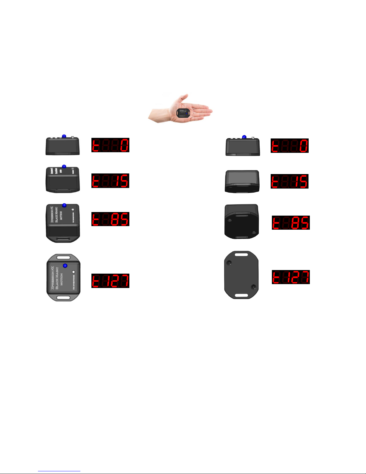
The tilt sensor measures tilt angle in any direction. Tilt mode must be calibrated before it can be used and
calibration should begin in one of six ideal orientations.
Orientations
There are six best orientations that tilt calibration can begin from.
Calibration begins in one orientation, and ends no further than the beginning of another orientation.
Calibration does not need to cover the full 90 degrees
Best results are obtained when calibration begins in one of these orientations and ends before entering
another orientation. However, greater than 90 degrees can be calibrated and the calibration does not need
to begin or end in the ideal orientations, rather these are ideal orientations that will provide best results.
Page 40
40
© Oz inventions
Version 1.8
Figure 16 –First direction
Figure 17 –Second direction
Testing tilt mode
1. Start the receiver modulator device with the default settings. See System reset
2. Change the polarity and resistance to those required by the device to be modulated. See System
menu items pg 23
3. Hold the sensor in the palm of your hand, with the LED facing up toward the sky. The edge nearest
the LED should be further from you compared to the other edge, and the strap holders should be
running along the axis from your fingers to your wrist.
Uni-directional tilt mode
Tilt your hand toward you and a
representation of the changing
level of modulation is seen on
the display. The default settings
are zero when the device is
horizontal with the ground and
127 when it is tilted 90 degrees.
The angle can be changed by
calibrating.
Bi-directional tilt mode
Turn on the bi-directional
switch. Hold the sensor on a
horizontal plane again and tilt
your hand forwards as
previously and the readings are
the same as previously. Now,
start with the sensor horizontal
again and tilt your hand
backwards. The default settings
are zero when the device is
horizontal with the ground and
127 when it is tilted 90 degrees
backward.
Page 41
41
© Oz inventions
Version 1.8
Understanding Quad tilt mode
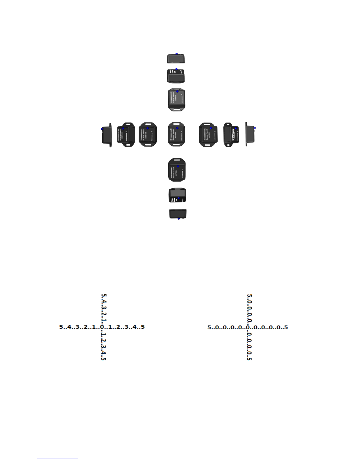
Quad tilt mode is similar to tilt mode but it allows tilting in four directions.
A full modulation swing from 0 – 127 is found on all four sides. This leaves only a very small zero point for
the user to rest in, and a small window for re-triggering the ADSR envelope, and so the sensitivity control
expands this window.
As the sensitivity control is moved clockwise higher values also begin to have a value of zero. This gives a
point of rest for the user because without this control there would always be some modulation as the user
quickly crosses over the zero point.
Figure 14 – Zero point window with sensitivity at 0 Figure 15 – Zero point window with sensitivity at 5
As with tilt mode, there are six best orientations from which calibration should start.
Page 42

42
© Oz inventions
Version 1.8
Testing quad tilt mode
1. Start the receiver modulator device with the default settings See System reset
2. pg 31
3. Change the polarity and resistance to those required by the device to be modulated. See System
menu items pg 23
4. Set sensitivity at zero (fully anti-clockwise)
5. Hold the sensor in the palm of your hand, with the LED facing up toward the sky.
6. Tilt the sensor left, right, forward and backwards and the display will change accordingly.
7. Notice that the zero point is not easy to find.
8. Turn the sensitivity control to 10
9. Tilt the sensor left, right, forward and backwards and the display will change accordingly.
10. Notice that the values that were reading from 1 – 9 are now all reading 0, effectively expanding the
zero point window.
Page 43
43
© Oz inventions
Version 1.8
Understanding rotation mode and Guitar-hand mode
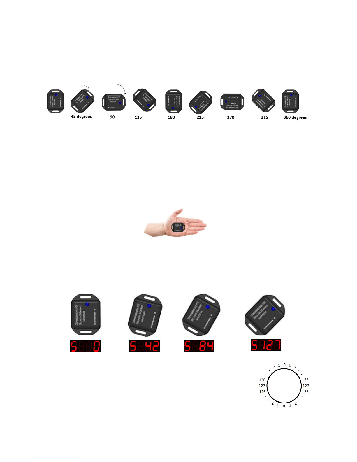
Rotation mode senses the distance moved in a circle (rotational angle).
The starting orientation for the rotation sensor is not important. However, when calibrating and using it, the
start and end Orientations should be similar. Regardless of the orientation of the rotation sensor the motion
must be parallel with the ground (horizontal).
Calibration for rotation mode can begin at any orientation and at any rotational angle and stop at any
rotational angle up to a maximum of 720 degrees (two full circles). The ending orientation should be the
same as the starting orientation. See Rotation and Guitar-hand mode calibration process pg 35
Testing rotation mode
1. Start the receiver modulator device with the default settings. See System reset
2. Change the polarity and resistance to those required by the device to be modulated. See System
menu items pg 23
3. Hold the sensor in the palm of your hand, with the LED facing up toward the sky.
4. Hold your arm out straight, parallel with the ground
5. In rotation mode watch the display as you begin to rotate your arm around your body
For Guitar-hand mode move your arm in any direction
6. The display will increase from 0 – 127 as you move in a clock wise direction, and decrease in the
other direction
Figure 16 – A 45 degree calibration
After passing the 127 point, the display will start decreasing as soon as the sensor
changes direction. For example if the display reaches 127 at 45 degrees, but the
sensor continues turning say to 90 degrees, when the direction is reversed the
display will immediately start to decrease. The same effect occurs at the zero degree
point. When the bidirectional switch is activated the output will continue in a circle
rather than cutting off at 0 and 127, as shown in the picture here.
Page 44
44
© Oz inventions
Version 1.8
Understanding Velocity mode
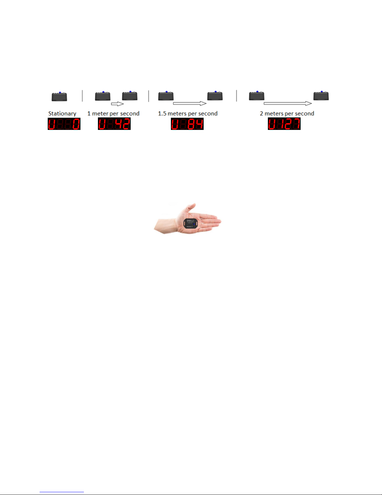
The velocity mode senses how quickly the sensor is moving in a circle.
The orientation of the velocity sensor is not important, and there is no calibration required. There is however
a sensitivity control. The sensitivity control adjusts how easily the modulation reaches maximum given a
specific velocity.
Testing velocity mode
1. Start the receiver modulator device with the default settings. See System reset
2. pg 31
3. Change the polarity and resistance to those required by the device to be modulated. See System
menu items pg 23
4. Set sensitivity to centre.
5. Hold the sensor in the palm of your hand, with the LED facing up toward the sky.
6. Hold your arm out straight, parallel with the ground
7. Watch the display as you begin to move your arm
8. The display will hold steady if the speed is steady
9. Slow down and speed up, and the display will react according
10. Adjust the sensitivity if the speed is not registering on the display
Straight line movements as well as circular movements are able to be made, with circular movements
creating a stronger reaction and hence require lower sensitivity settings.
Page 45
45
© Oz inventions
Version 1.8
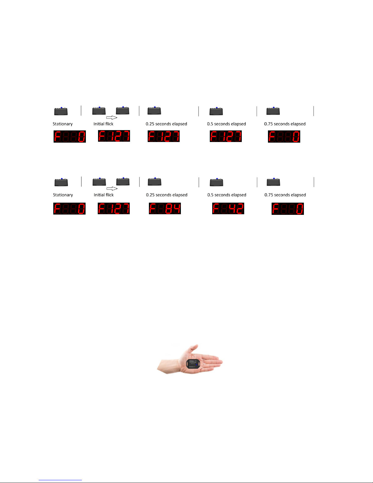
Understanding Flick mode
Flick mode senses how forcefully the sensor is moved. It is based on acceleration and so unlike velocity mode
the display will return to zero very quickly after the initial movement even though it may still be moving.
Unless it is actually accelerating, modulation will not occur. Therefore the Flick sensor works well with the
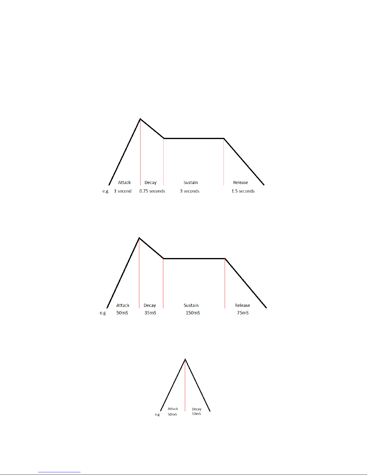
ADSR envelope. The ADSR envelope will hold the display for a period of time after the initial Flick. The hold
period can be from fractions of a second up to 5 minutes and can include the characteristics of an ADSR
envelope.
Figure 17 – The ADSR envelope can hold the output at maximum
Figure 18 – The ADSR envelope can be adjusted to let the output fall gradually
The ADSR envelope is fully configurable and so the rise time, decay time, sustain level, sustain time and
release time can all be adjusted, giving Flick mode a range of possibilities.
The orientation is not important for Flick mode and there is no calibration required. There is however a
sensitivity control. The sensitivity control adjusts how much force is required to reach maximum output.
Testing Flick mode
1. Start the receiver modulator device with the default settings. See System reset
2. Change the polarity and resistance to those required by the device to be modulated. (See System
menu items pg 23)
3. Set sensitivity to centre
4. Hold the sensor in the palm of your hand, with the LED facing up toward the sky.
5. Watch the display as you flick your hand to apply some force to the sensor
6. The display will increase and decrease very quickly
7. Adjust the sensitivity control so that a flick of the sensor creates the maximum modulating output
(127)
8. Flick mode works well as a trigger for the ADSR envelope. See ADSR trigger mode pg 48
Page 46
46
© Oz inventions
Version 1.8
Understanding ADSR, Automatic ADSR mode and ADSR trigger mode
ADSR
The ADSR (Attack, Decay, Sustain & Release) items control the ADSR envelope shape. The envelope can be
triggered using one of the modulation mode outputs, or the envelope can be automatically triggered. The
time periods for each section of the envelope, (Attack rate, Decay rate, Sustain level, sustain time & Release
rate) are individually adjustable.
Long duration envelopes like the one shown below are used to make changes that slowly increase and/or
decrease, such as arpeggios. The maximum period is 5 minutes.
Figure 19 – Long duration envelope
The picture below shows a short duration envelope in the range of milliseconds. Short envelopes make good
tremolo and vibrato effects from pitch and volume parameters.
Figure 20 – Shot duration envelope
Not all sections of the ADSR envelope need to be used. The picture below shows only the attack and decay
sections in use.
Figure 21 – Limited section envelope
Page 47
47
© Oz inventions
Version 1.8
ADSR menu
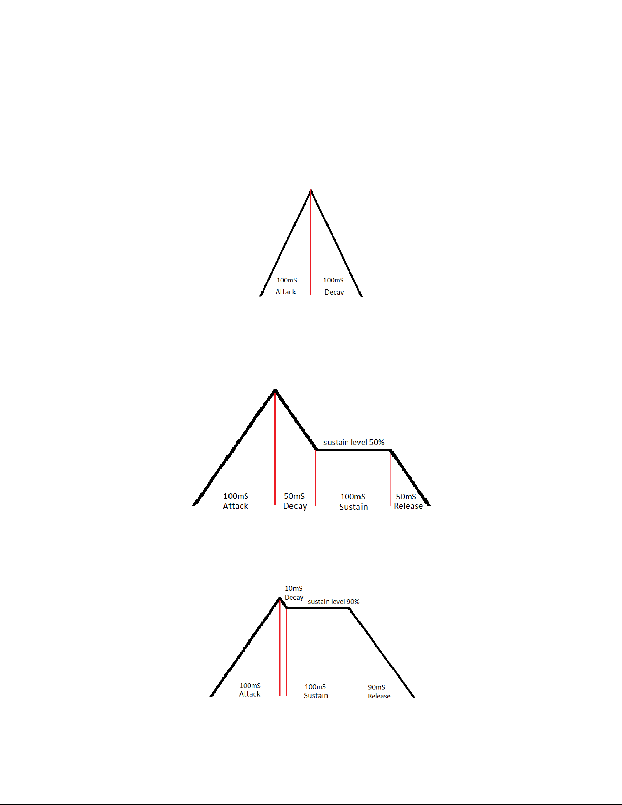
The ADSR menu consists of the stages of attack rate, decay rate, sustain level, sustain time and release rate.
There is also an overall scale adjustment, and also ADSR trigger modes.
The rates can be set between 0 and 99. Each increment equates to 10 milliseconds for the attack rate and
sustain time. The sustain level is adjustable between 0 and 100%. The decay rate and release rates combine
in ratios dependent on the sustain level. Assuming the sustain level is 0, then the decay rate value
corresponds to increments of 10 milliseconds. The figure below shows that it takes the same time to rise as
it does to fall, for an attack rate of 10 and a decay rate of 10.
If, however the sustain level is at say 50%, then it will only take half as long to reach the sustain level, and so
each increment of the decay rate is actually 5 milliseconds. In addition there now must be some time
available to release from the sustain level and fall to zero. This is made up by the release rate whose
increments will also be at 5 milliseconds.
Figure 22 – Decay and release combine to form a single time section
As a final example, if the sustain level is set at 90% then the decay time will be 10 milliseconds and the
release time 90 milliseconds.
Figure 23 – Release rate increases and decay rate decreases
Page 48

48
© Oz inventions
Version 1.8
Automatic ADSR mode
Automatic ADSR mode will play the ADSR envelope, as set within the menu, over and over again. Automatic
ADSR mode is selected with the modulation mode switch choosing ‘A’.
Testing automatic ADSR mode
1. Start the modulator with the default settings See System reset
2. pg 31
3. Choose a parameter to modulate on an effect unit, keyboard or MIDI controller
4. Select ‘A’ using the mode switch and the ADSR envelop will immediately start playing.
5. Press the on/off/calibration switch so that the ON LED lights
6. Play a note on an instrument, and the modulation will be heard.
The modulation waveform will be using the default ADSR parameters in the system menu.
7. Access the menu (mode switch + on/off/calibration switch)
8. Rotate the minimum depth control to find “Ar” (Attack rate). This sets how quickly the envelop rises.
Set this to 10 using the max depth control.
9. Rotate the min depth control further until “dr” (decay rate) is found. This sets how quickly the
envelope will fall to the sustain level. Set this to 10 using the max depth control.
10. Continue to rotate the minimum depth control set SL (sustain level), St (sustain time) and rr (release
rate) to zero.
11. Rotate the min depth control to find the Sc (scale setting). This adjusts the overall time for the
envelope. Set this at 5.
12. Play a note on the instrument being modulated and the modulation will be heard.
13. Adjust the scale setting for the overall length required.
14. In this example the attack and decay have both been set for 10 x 10 milliseconds. That equates to a 5
Hz vibration (5 times a second backwards and forwards). Settings less than five milliseconds can have
unpredictable but interesting results, depending on the other ADSR settings.
ADSR trigger mode
Trigger mode is used to trigger the ADSR envelope. ‘Atrg’ must be selected from the system menu for trigger
mode to function. The maximum modulating output of 127 in any modulation mode, will trigger the ADSR
envelope. The shape of the envelop is set in the menu. The stages of the envelope can be set with a
minimum time of 50 milliseconds and a maximum of 99 seconds which gives a wide range of possibilities.
When the overall envelope shape is set, the scale setting can be used to vary the time over which the entire
envelop executes.
There are three trigger modes
1. One shot (tnno)
When the modulating output reaches the maximum depth the envelope starts and completes. If the
modulation output remains at the maximum depth, the envelope will repeat.
2. Hold (tnnH )
When the modulating output reaches the maximum depth the envelope starts and holds at the
sustain section until the modulating output reaches maximum again, at which time the envelope
finishes sustain, begins release, and completes.
3. Repeat (tnnr)
Page 49

49
© Oz inventions
Version 1.8
When the modulating output reaches maximum the envelope repeats continuously until the
modulating output reaches maximum again, at which time the current repetition completes and
stops.
The maximum depth sets the point at which modulation will trigger the envelope. If a higher point is needed
a higher angle should be set using calibration.
Testing ADSR trigger mode
1. Choose a parameter to modulate on an effect unit, keyboard or MIDI controller
2. Start the receiver modulator device with the default settings See System reset
3. Open the system menu (Mode switch + on/off/calibration switch)
4. Scroll through the menu and set ADSR trigger mode on ( select ‘Atrg’ from ‘Free / Rec / Atrg’
5. Scroll through the menu and set AR to 30 (Attack rate 30 x 10mS = 300 milliseconds). The default
settings for the other envelope values will be OK.
6. Scroll through the menu and set the trigger mode to trigger the envelope just once (‘tnno – Trigger
One shot)
7. Exit the menu (Mode switch + on/off/calibration switch)
8. Change to Flick modulation mode
9. Flick the sensor so that a modulating output of 127* is read on the display
10. The envelope will play once using the ADSR settings. Attack rate is 30 so there will be a slow rise
before the envelope completes
11.
o Change the trigger mode to hold. (‘tnnh’ – Trigger Hold)
o Flick the sensor so that a modulating output of 127 is read on the display
o The ADSR envelop will start and stay in the sustain section indefinitely
o Flick the sensor again, and the envelop will complete
12.
o Change the trigger mode to repeat. (‘tnnr’ – Trigger Repeat)
o Flick the sensor so that a modulating output of 127 is read on the display
o The ADSR envelop will repeat continuously
o Flick the sensor again, and the envelop will stop repeating
The sensitivity control has no effect at all when in automatic ADSR envelope. When in ADSR trigger mode the
sensitivity control functions as it would for any modulation mode, as a sensitivity control for the type of
motion.
*An output level of 127 is required to trigger an envelope. Re-calibrate in tilt or rotation modes, or adjust the
sensitivity in velocity or flick mode, to change where 127 is reached. The maximum and minimum depth
controls are still functional.
Page 50
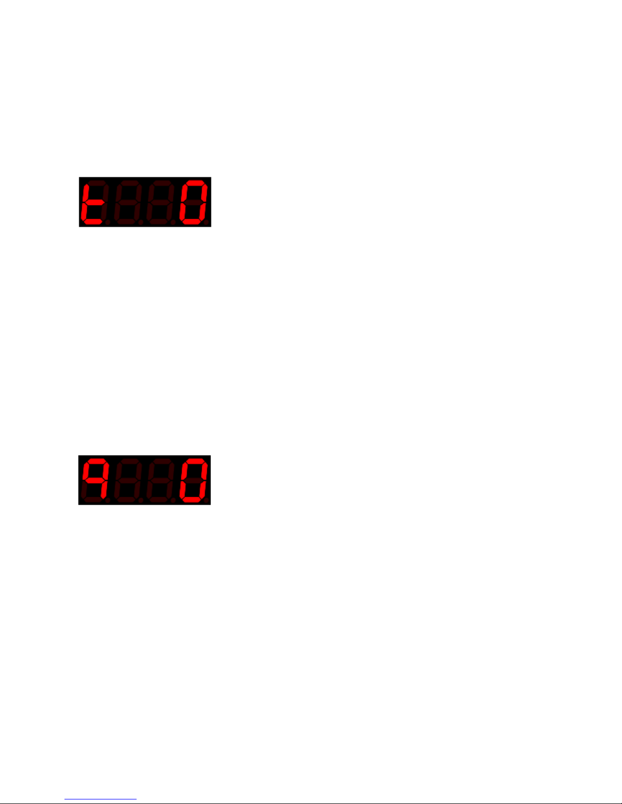
50
© Oz inventions
Version 1.8
Useful settings
There are many ways the device can be used and setup. The following list is not exhaustive, but provides a
place to start.
Tilt
Tilt is useful for all sorts of effect parameters. It is a stable mode that will accurately display the angle held. It
is particularly good for modulating the bandwidth filter of a Wah Wah effect, with the sensitivity control fully
clockwise.
1. Choose a Wah Wah effect parameter
2. Set min depth to minimum (fully anti-clockwise)
3. Set the max depth to maximum (fully clockwise)
4. Set the sensitivity to 99 (fully clockwise).
5. Press the on/off/calibration switch so that the ON LED lights.
6. Place the sensor on the back of the leg, below the knee and on the top of the calf.
7. Keep the leg straight and calibrate whilst bending the knee downwards over a small angle (20
degrees)
8. The sensor unit can now be tilted backwards and forwards quickly to modulate the bandwidth filter.
9. Try it with the bi-directional switch in both positions
10. Try it with sensor mounted on an instrument or other body part
11. Set the min depth control a little as needed to start the bandwidth filter with a brighter tone
Quad tilt
Quad tilt data is obtained over angles in four directions. Quad tilt is useful for continuous modulation.
As with ‘Tilt’ mode, using the six best starting orientations, and tilting no further than 90 degrees is a failsafe
method, though good results can still be obtained starting on an angle and/or tilting further than 90 degrees,
depending on starting and finishing orientations.
See Orientations
Page 51
51
© Oz inventions
Version 1.8
Rotation
Rotation is useful for many effect parameters as it can be held in place and the effect parameter can be
turned on and off easily. Rotation is always clockwise or anti-clockwise. Holding the sensor in different
orientations does make some difference and so it is best to start and finish in the same orientation.
The sensitivity control and bi-directional switch have no effect on rotation.
Choose a distortion effect parameter
Set min depth to minimum (fully anti-clockwise)
Set the max depth to maximum (fully clockwise)
Press the on/off/calibration switch so that the ON LED lights.
Place the sensor on the headstock or body of a guitar
Calibrate horizontal to the ground, moving left to right over a medium angle (45 degrees)
The sensor can now be moved backward and forward and the distortion effect will increase as it is
turned. Hold the sensor at the point where you are happy with the effect level.
When ready, swing back in the other direction to lower or stop the effect
Adjust the maximum depth control to limit the level of distortion, and/or the minimum depth
control to keep the distortion from disappearing completely.
Velocity
Velocity is a little like rotation, but rather than the effect parameter being held, when the sensor stops, the
modulation will return to zero and stop.
There is no angle calibration required for velocity, but the sensitivity control may need to be adjusted.
Move the sensor and note how quickly it needs to be moved to reach full modulation level (127).
The sensitivity control changes how fast the sensor needs to be moved to reach full modulation
level. You will need some trial and error testing, but start with the sensitivity control at 75 (3/4
clockwise). If you don’t get the modulation level needed, either move the sensor faster or increase
the sensitivity control.
Choose a vibrato or tremolo effect parameter
Set the bidirectional switch ON
Press the on/off/calibration switch so that the ON LED lights.
Place the sensor on the headstock or body of a guitar
The sensor can now be moved backwards and forwards and the effect will be heard to modulate and
then cease when the sensor ceases
Try it with the bidirectional switch OFF and the modulation will only occur in one direction.
Page 52

52
© Oz inventions
Version 1.8
Flick
Flick on its own will produce a very short modulation as it decreases very quickly and so it is used when there
are very quick hand movements, such as up and down a guitar neck or keyboard. It can also be used with
ADSR trigger mode. The trigger can hold the setting for a period of time and/or slow the modulations rise
and fall, thereby increasing the time of modulation and adding interesting sounds.
The bidirectional switch has little effect upon Flick as an equal and opposite impulse occurs in any direction.
The sensitivity control adjusts how much force is needed for the modulation output to reach maximum(127).
It will take testing to determine the correct setting.
1. Start with the sensitivity control at 75 (3/4 clockwise), flick the sensor and note how close to full
modulation is achieved. Adjust the control as needed or flick the sensor harder.
2. Choose an echo rate effect parameter
3. Set min depth to minimum (fully anti-clockwise)
4. Set the max depth to maximum (fully clockwise)
5. Press the on/off/calibration switch so that the ON LED lights.
6. Place the sensor on the back of a hand. That can be the fretting hand or strumming hand for a guitar,
or either hand for a keyboard.
7. Play notes and move the hand rapidly before and/or after to hear the effect.
8. Try waving the hand in mid-air to get a feel for what is happening
9. You will notice the modulation does not last for long, and so ADSR triggering can be used.
10. Open the menu and select ‘AtrG’ (AtrG trigger mode) from the first menu
11. Select ‘tnnH’ (trigger mode Hold) from the menu.
12. Exit the menu
13. Move the sensor back and forth and the ADSR envelope will play each time the maximum depth is
reached.
The envelop settings can be adjusted in the menu to change the length of hold, and/or to change the
type of trigger mode. ‘See ADSR trigger mode 48’
Page 53
53
© Oz inventions
Version 1.8
Guitar-hand
Guitar-hand is useful for many effect parameters and is designed for used with the strumming or picking
guitar. It produces modulation from rotation in any direction.
The sensitivity control and bi-directional switch have no effect in guitar-hand mode.
Choose a Wah-Wah effect parameter
Set min depth to minimum (fully anti-clockwise)
Set the max depth to maximum (fully clockwise)
Press the on/off/calibration switch so that the ON LED lights.
Place the sensor on the strumming hand
Calibrate over the distance that your hand moves when strumming
The hand can now strum and the Wah-Wah effect will increase and decrease.
Adjust the minimum and/or maximum depth controls to limit the level of Wah-Wah effect
Automatic
Automatic mode is used with the ADSR envelope shaper. The envelope parameters are set within the menu
and then the envelope will modulate the output whenever Automatic mode is selected
The default settings provide a very quick modulation useful for tremolo and vibrato effects. High settings
create long waveforms that add an element of randomness to the sound.
Choose an effect to modulate
Select Automatic ADSR (‘A’) with the modulation mode switch
Turn modulation on with the On/Off/Calibrate/record switch
Playback / Record
Playback enables playback of a previously recorded motion controlled waveform that can be used to
modulate an effect parameter.
Calibration cannot be done when in record mode. If calibration is needed, it should be done before moving
into record mode.
See Understanding recording pg 37
Page 54

54
© Oz inventions
Version 1.8
Using the modulator as a foot switch
Some effects units/keyboards/MIDI controllers, have sustain sockets, footswitch sockets or expression
sockets that have foot switch functionality. The function of the switch, as well as the type of footswitch
required, is dependent on the brand and model. Footswitches may be momentary or latched, footswitch
devices may contain a single footswitch or two or three switches. The function of a footswitch may be to
change presets, change banks, start and stop loopers and select other built-in functions. The specific devices
user manual will need to be referenced. There are many types and this modulator will not function as a
footswitch will all of them. Some examples are shown here -
Zoom® effect products often have an expression socket that also accepts a footswitch. The footswitch
required is a single switch connected to a TS (mono) cable. To use this modulator as a footswitch with these
products set the polarity to TS and use a TS (mono) cable. The switching can be activated in three ways
1. Turn the minimum depth control to fully clockwise (127). The on/off/calibrate button or remote
on/off function can now be used for switching.
2. Set the step size to 127; turn modulation on; The modulation can now activate switching in any
modulation mode
3. A pre-recorded motion pattern will activate switching, whenever maximum output (127) or zero is
reached
TC Helicon ® effects often use a three switch unit with a TRS cable. Switch one is activated by joining tip to
sleeve; Switch two is activated by joining ring to sleeve; Switch three is activated by having the tip joined to
the ring, and then joining them to the sleeve.
All three switches can be simulated by the modulator, but only one at a time. The switching is enabled in the
following ways –
Switch 1 – Set the modulator to TRS
Switch 2 – Set the modulator to RTS
Switch 3 – Set the modulator to RS
The switching can be activated in three ways
1. Turn the minimum depth control to fully clockwise (127). The on/off/calibrate button or remote
on/off function can now be used for switching.
2. Set the step size to 127; turn modulation on; Modulation can now activate switching in any
modulation mode
3. A pre-recorded motion pattern will activate switching whenever the maximum output (127) or zero
is reached
There are many devices available that have footswitches that interface in different ways and so the devices
user manual needs to be referenced to setup the function of the footswitches and also the type (momentary
/ latched).
Page 55

55
© Oz inventions
Version 1.8
Default settings
The following parameters are found at first power on and after a factory reset.
System Menu item
Default parameter
Step size Menu item
Default parameter
Soft power On/Off
Off (0)
Step size
1
Use mode
Free 1 20
Resistance
12Kohms
2
26
Channel
Red 3
Polarity
TRS 4
Log / linear scale
Linear 5
Automatic cutoff
2 seconds
6 Record trigger level
10 7
Record time
1 8
Reverse sweep
No 9
ADSR items
10 Attack rate
5
11 Decay rate
5
12
127
Sustain level
50%
13 Sustain time
2
14 Release rate
5
15 16
Scale
1 x the entire
waveform
Preset*
0
Trigger mode
Repeat
*All ten available presets have the same default system, calibration, ADSR and step size, settings
Tilt mode
Orientation
Top
Minimum depth
0 @ 0 degrees
Maximum depth
127 @ 90 degrees
Quad Tilt mode
Orientation
Top
Minimum depth
0 @ 0 degrees
Maximum depth
127 @ 90 degrees
Rotate
Minimum depth
0 @ 0 degrees
Maximum depth
127 @ 90 degrees
Guitar-hand
Minimum depth
0 @ 0 degrees
Maximum depth
127 @ 90 degrees
The default settings can be restored by using the system reset function (pg 31).
Page 56

56
© Oz inventions
Version 1.8
Menu item order
System items
Item
Identifier
Range
Soft power On/Off
So
0 - 99
Use mode
Free / AtrG / Rec
Free / AtrG / Rec
Resistance
R
12, 25, 50
Channel
Ch
r, g, b
Polarity
P
trS, rtS, tS, rS, CV
Logarithmic / Linear scale
Log
-, L, A
Auto-cutoff
Ao
0 – 99
Trigger level
tL
0 – 99
Record time
Rt
1-99
Reverse sweep
rS
No / Yes
ADSR items
Item
Identifier
Range
Attack rate
Ar
0 - 99
Decay rate
Dr
0 - 99
Sustain level
SL
0 – 99
Sustain time
St
0 – 99
Release rate
Rr
0 – 99
Scale
SC
1 – 99
Trigger mode
T
nnr / nnH / nnr
quit / save
quit /save
quit / save
Step size items
Item
Identifier
Range
Step size
S
0 – 127
Step 1
1
0 – 127
Step 2
2
0 – 127
Step 3
3
0 – 127
Step 4
4
0 – 127
Step 5
5
0 – 127
Step 6
6
0 – 127
Step 7
7
0 – 127
Step 8
8
0 – 127
Step 9
9
0 – 127
Step 10
10
0 – 127
Step 11
11
0 – 127
Step 12
12
0 – 127
Step 13
12
0 – 127
Step 14
12
0 – 127
Step 15
12
0 – 127
Step 16
12
0 – 127
quit / save
quit /save
quit / save
Preset items
Item
Identifier
Range
Preset
PS
0 – 9
Page 57

57
© Oz inventions
Version 1.8
Step size settings for various devices
Arturia® MiniBrute
2 4 6 9 11
14
16
19
21
24
26
29
C# D D# E F
F# G G# A A# B C
Yamaha® MOTIF XS6
6 9 11
14
16
19
22
24
27
31
32
35
C# D D# E F
F# G G# A A# B C
Zoom guitar effects G series®
20
26
33
40
48
58
66
76
88
98
111
127
C# D D# E F
F# G G# A A# B C
____________
____________
__________
____________
____________
Page 58

58
© Oz inventions
Version 1.8
A final note
There are many ways to use the modulator. This is the only device of its type available and we expect it will
change the way you play music. There are many features and it will take some time to learn and master
them all.
The way the modulator is used is defined by what it is connected to. Briefly -
A multi-effects unit often enables modulation over all or most effect parameters such as tremolo,
vibrato, echo rate, distortion and Wah Wah.
A single effect unit (stomp box) may only offer modulation on one parameter, but sometimes there
are several parameters.
An analog synthesizer enables ADSR shaping on pitch, filter and/or amplitude
A MIDI controller enables expression control over many assignable parameters such as pitch and
volume.
A keyboard with an expression socket often enables assigning expression to volume pitch, pan,
resonance, filter, tempo, registration, looping, drum machine start/stop, just to name a few
The modulator can be used as a footswitch and/or sustain pedal
Knowing what the expression can be assigned to is the key to knowing what the modulator can do. And so,
the user guide for the effects unit / Keyboard / MIDI controller should be consulted.
The wireless motion control system is an innovative and unusual item. It is unlikely that a user will be
familiar with its use and so some time testing and practicing will be beneficial.
The sensor can be placed on anything that moves. Examples are
A guitar, arm, leg, saxophone, dancer, rotating wheel, spinning chair, vibrating item etc.
The sensor reacts to tilt, large & small circular movements, speed and flicking motions.
The modulation can be applied to any assignable parameter available on an effects unit / keyboard /
or MIDI controller.
Multiple modulator-receivers can be used
Multiple sensor-transmitters can be used
The limits are in the imagination
Page 59

59
© Oz inventions
Version 1.8
Trouble shooting
Problem
Resolution
The display and modulation does not change
Check minimum depth control
Check maximum depth control
Check sensitivity control
The display and modulation are slow to change in tilt
mode
Increase sensitivity control
Modulation is too sensitive
Reduce sensitivity control
Nothing is playing back after a recording
Reduce sensitivity control (trim)
The display only changes a little in flick or velocity modes
Increase sensitivity control
The channel indicator is not lit
Match channel to sensor-transmitter channel
Modulation is not smooth or jumps large steps
Check polarity setting and/or resistance settings
Display is functioning smoothly but there is no modulation
effect
Turn modulation on
Check polarity and/or resistance settings
Check setup of device being modulated
Modulation jumps in steps
Normal operation. Check ‘step size’ setting and/or
linear/logarithmic settings
Recording is armed but does not begin
Record trigger level set too high
The angle over which modulation occurs is too large or
too small
Re-calibrate
No lights and no display
Check power adapter configuration
Channel indicator blinks
Poor reception
Attach antenna
Stay within range of sensor-transmitter
Antenna is not vertical
Calibration is not working
Check that ‘free’ or ‘AtrG’ mode is selected in menu
Modulation is not triggering the ADSR envelope on and/or
not triggering it off
Ensure that maximum depth is being reached to trigger
the envelope
Rotation mode not working when moved up and down
Normal operation. Rotation mode only works on a
horizontal plane
Automatic ADSR modulation is not smooth
Check ADSR settings. Settings less than 5 for attack and
decay rates simultaneously whilst the scale is less than 2,
are not supported
Menu cannot be accessed or exited
Ensure the correct order of switch and controls is used (pg
21)
Not working properly after menu exited
Check minimum depth control
Check maximum depth control
Check sensitivity control
Not working properly after modulation mode changed
Check minimum depth control
Check maximum depth control
Check sensitivity control
Modulation keeps turning on and off
Check ‘Soft power on/off’ as it may be set to low and
thereby causing modulation to turn on/off as tilting etc is
occurring.
Many menu item values have changed accidently
Be careful not to move the maximum depth control when
moving through the menu items with the minimum depth
control
The automatic arpeggiator timing is off
Adjust the maximum and/or minimum depth controls as
required
The controls skip a number
Turn the control slowly or turn the control to maximum
and try again
Everything has been tried, but it won’t work, or it seems
stuck
Turn power off and on
Load default settings (system reset)
Contact Oz Inventions
Page 60

60
© Oz inventions
Version 1.8
Modulator-Receiver specifications
9 – 12 volt; Negative centre (tip)
Current draw 60 – 80mA
Expression connection electrical resistance 12Kohm, 25Kohm and 50Kohm
Expression jack type- ¼” (6.35mm) stereo
Polarity - TRS, RTS, TS, RS or CV (0 – 5v; 2mA maximum)
2.4GHz receiver
Dimensions - L 112mm x W 60.5mm x H 31mm
Weight - 0.175 Kg (175 grams)
Page 61

61
© Oz inventions
Version 1.8
Index
(PS), 33
ADSR, 16, 46
ADSR items, 29
Anti-Logarithmic, 26
Ar, 29
AtrG, 23
Attack Rate, 29
Calibration, 34
Ch, 24
Channel, 24
CV, 26
Decay Rate, 29
Default settings, 55
Display, 20
dr, 29
F, 16
Flick mode, 45
foot switch, 54
Free, 23
G, 16
Guitar-hand, 43
Indicator lights, 20
Linear, 26
LoG-, 26
LoGA, 26
Logarithmic, 26
LoGL, 26
Max depth, 18
Menu access, 21
Min depth, 18
modulation modes, 39
Orientations, 35, 39, 50
P, 25
Polarity, 25
Presets, 33
Quad tilt mode, 41
quit, 27
r, 24
Rec, 24
Record trigger level, 27
recording, 37
Recording time, 27
reset, 22, 31
Resistance, 24
Reverse sweep, 27
rotation mode, 43
rs, 27
RS, 26
rt, 27
RTS, 25
S, 32
Save, 27
Sc, 31
Scale, 31
Sensitivity control, 17
SL, 29
Soft power On/Off, 23
specifications, 60
St, 29
Step size, 32
Sustain Level, 29
Sustain Time, 29
System items, 23
tilt mode, 39
tL, 27
tnn, 30
tnnH, 30
tnno, 30
tnnr, 30
trigger mode, 48
Trigger mode, 30
Trim, 37
Trouble shooting, 59
TRS, 25
TS, 25
Velocity mode, 44
 Loading...