


Security
&
Home Automation System
AX1 LCD & ICON
USER MANUAL
(REVISION 4.0)

AX1 LCD & ICON User Manual Rev 4.0

AX1 LCD & ICON User Manual Rev 4.0
CONTENTS
PREFACE
FEATURES
AX1 LCD USER MANUAL
LCD KEYPAD OUTLOOK
1.0 ARMING MODE
2.0 SOUND INDICATION
3.0 LIGHT INDICATION
4.0 KEYPAD NAVIGATION KEY FUNCTION
OVERALL LCD KEYPAD MENU TREE
CHAPTER 1: ALARM SYSTEM CONTROL
1.0 ALARM SYSTEM CONTROL USING LCD KEYPAD
1.0.1 SECURITY MENU
1.0.2 ARMING
1.0.2.1 QUICK ARMING
1.0.3 DISARMING
1.0.4 ALARM REPORTING
1.0.5 CLEAR ALARM MEMORY
1.0.5.1 QUICK CLEAR ALARM MEMORY
1.0.6 BYPASSING ZONE
1.0.6.1 QUICK BYPASSING ZONE
1.0.7 ZONE STATUS VIEWING
1.0.7.1 QUICK VIEW ON ZONE DESCRIPTION
1.0.7.2 QUICK ZONE STATUS VIEWING
1
2
4
5
6
7
7
7
8
11
11
11
14
14
15
15
16
16
17
17
18
18
18
i

AX1 LCD & ICON User Manual Rev 4.0
CHAPTER 2: HOME AUTOMATION CONTROL
2.0 INTRODUCTION
2.1 AUTOMATION CONTROL USING LCD KEYPAD
2.1.1 QUICK AUTOMATION CONTROL
2.1.2 QUICK VIEW OF OUTPUT DESCRIPTION
2.1.3 QUICK VIEW OF OUTPUT STATUS
19
19
20
20
20
20
CHAPTER 3: USER PROGRAMMING
3.0 USER SETTING EDIT
3.0.1 MASTER USER
3.0.2 USER
3.0.3 GUEST
3.0.4 INSTALLER ACCESS
3.0.5 TIMER
3.0.6 DURESS
CHAPTER 4: KEYPAD SETTINGS
4.0.1 QUICK CHIME ENABLE
4.0.2 QUICK VOLUME CONTROL
4.1 PHONE LINE LOSS DETECTION
CHAPTER 5: SECURITY & AUTOMATION CONTROL
THROUGH TELEPHONE
5.0 SYSTEM CONTROL THROUGH TELEPHONE
5.1 SYSTEM CONTROL WITH VOICE INTERFACE
THROUGH CALL-IN
5.2 SYSTEM CONTROL WITH BEEPER INTERFACE
THROUGH CALL-IN
21
21
22
23
24
25
26
27
28
28
28
29
30
30
30
31
ii

AX1 LCD & ICON User Manual Rev 4.0
CHAPTER 6: WHEN THERE IS AN EMERGENCY
6.0 EMERGENCY ALARM
6.1 DURESS ALARM (CALLING FOR HELP)
6.2 TELEPHONE ALERT TO USER
6.2.1 SYSTEM CALL-OUT WITH VOICE INTERFACE
6.2.2 SYSTEM CALL-OUT WITH BEEPER INTERFACE
CHAPTER 7: SYSTEM CHECKING
7.0 TROUBLE
7.0.1 TROUBLE VIEWING BY USING KEYPAD
7.0.1.1 QUICKVIEW TROUBLE
7.1 TESTING SYSTEM BY USING KEYPAD
7.2 EVENT LOG VIEWING
7.2.1 THE EVENT LOG DISPLAY FORMAT
7.2.2 EVENT LOG EXAMPLE
AX1 ICON USER MANUAL
ICON KEYPAD OUTLOOK
1.0 ARMING MODE
2.0 SOUND INDICATION
3.0 LIGHT INDICATION
4.0 KEYPAD NAVIGATION KEY FUNCTION
CHAPTER 1: ALARM SYSTEM CONTROL
1.0 ALARM CONTROL USING ICON KEYPAD
1.0.1 ARMING
1.0.1.1 QUICK ARMING
1.0.2 DISARMING
1.0.2.1 IN ARMED MODE
1.0.2.2 IN ALARM MODE
32
32
32
32
33
34
35
35
35
35
36
37
38
38
39
40
41
42
42
42
43
43
43
43
44
44
44
iii

AX1 LCD & ICON User Manual Rev 4.0
1.0.3 ALARM REPORT
1.0.4 CLEAR ALARM MEMORY
1.0.5 BYPASSING ZONE
1.0.5.1 QUICK BYPASSING ZONE
CHAPTER 2: HOME AUTOMATION CONTROL
2.0 INTRODUCTION
2.1 AUTOMATION CONTROL USING ICON KEYPAD
CHAPTER 3: VIEW TIMER MODE
CHAPTER 4: USER PROGRAMMING
4.0 USER SETTING EDIT
4.0.1 MASTER USER
4.0.2 USER
4.0.3 GUEST
4.0.4 DURESS
4.0.5 TIMER
4.0.5.1 IO ON
4.0.5.2 IO OFF
4.0.5.3 ARM
4.0.5.4 DISARM
4.0.6 CLOCK
4.0.7 INSTALLER ACCESS
4.0.8 FAST KEY ACCESS
4.0.9 PHONE LINE LOSS DETECTION
4.0.10 PC COMM
CHAPTER 5: KEYPAD SETTINGS
5.1 DOOR CHIME
5.2 KEYPAD SETTING VIEW
45
45
46
46
47
47
48
49
50
52
52
53
54
55
56
56
57
58
59
60
61
62
63
64
65
65
66
iv

AX1 LCD & ICON User Manual Rev 4.0
CHAPTER 6: SECURITY & AUTOMATION CONTROL
THROUGH TELEPHONE
6.0 SYSTEM CONTROL THROUGH TELEPHONE
6.1 SYSTEM CONTROL WITH VOICE INTERFACE
THROUGH CALL-IN
6.2 SYSTEM CONTROL WITH BEEPER INTERFACE
THROUGH CALL-IN
CHAPTER 7: WHEN THERE IS AN EMERGENCY
7.0 EMERGENCY ALARM
7.1 DURESS ALARM (CALLING FOR HELP)
7.2 TAMPER LOSS AND PHONE LINE LOSS ALARM
7.3 TELEPHONE ALERT TO USER
7.3.1 SYSTEM CALL-OUT WITH VOICE INTERFACE
7.3.2 SYSTEM CALL-OUT WITH BEEPER INTERFACE
CHAPTER 8: SYSTEM CHECKING
8.0 TROUBLE VIEW
8.1 TESTING SYSTEM
8.1.1 QUICK TROUBLE VIEW
APPENDIX A
GLOSSARY
LIMITATIONS
SYSTEM INFORMATION
AX1 LCD QUICK REFERENCE
HISTORY OF VERSION UPDATE
67
67
67
68
69
69
70
70
71
72
73
74
74
76
77
78
79
80
81
85
86
v

AX1 LCD & ICON User Manual Rev 4.0
PREFACE
Thank you for selecting the new AX1 Security and Home Automation system. This manual
will explain to you on how to operate your AX1 security and home automation system. This
system is made up of a control panel, keypads, integrated switch module and telephone voice
module. Specific areas of detections are called zones. Zones can be programmed to have
different characteristics. Some zones may be 24-hour zones; they remain armed even when
the alarm system is asleep. (This setting is done during the installer programming as per
user‟s request). In addition, some zones can be programmed by the users to allow bypassing.
When you bypass a zone, the zone is temporarily removed from the alarm system. Always
remember that bypassed zones are not protected.
How does your AX1 security and home automation system work?
When a detection device is triggered, the zone indicator will light up. If the alarm system is
armed, the control panel responds by reporting an alarm condition. The control of the system
can be done either through keypad or telephone. If the alarm system is triggered, the signal
can be transmitted to a central monitoring station (CMS). (Provided the AX1 system is
connected to CMS)
For safety purposes, the operation of the AX1 system requires the users to enter the personal
identification number (PIN). User is advised to disable the installer access whenever
necessary. (i.e. commissioning and servicing)
1

AX1 LCD & ICON User Manual Rev 4.0
FEATURES
AX1 LCD
1. 8 fully programmable zones (expandable to 32 zones)
2. Expandable up to 32 output controls (with feedback capability)
3. Supports up to 8 LCD keypads
4. 4 Real time ARM/DISARM timer on Daily basis or Schedule basic.
5. 4 Real time ON/OFF timer on Daily basis or Schedule basic.
6. 12 user codes & 4 guest codes
7. Ability to divide into 4 partitions
8. 4 programmable Outputs (OC)
9. Customizable Zone Naming Indicator
10. Customizable Output Naming Indicator
11. Event Log viewing
12. 16 Event Trigger Outputs with programmable countdown timer
AX1 ICON
1. 8 fully programmable zones
2. Expandable up to 8 output controls (with feedback capability)
3. Supports up to 4 ICON keypads
4. 1 Real time ARM/DISARM timer on Daily Basis only.
5. 4 Real time ON/OFF timer on daily basis
6. 7 user codes & 1 guest code
7. 8 Event Trigger Outputs
2

AX1 LCD & ICON User Manual Rev 4.0
AX1 ICON and LCD
1. 3 Soft Zones (Emergency/Fire/Panic)
2. 2 Programming Mode- Installer Programming and User Programming
3. 4 User Arming type (Auto home arming/ Day arming/ Night arming / Force arming)
4. Real time clock function
5. Programmable Entry/Exit Delay Time
6. 4 bell types (Steady/ Pulse/ Chirp/ Silent)
7. 3 zone types [End-of-line (EOL) / Normally Open (NO) / Normally Close (NC)]
8. Adjustable loop response sensitivity
9. Key Switch function (Latch/ Momentary)
10. Dedicated Tamper zone
11. AC power supply monitoring
12. Low battery indication
13. Bell Loss indication
14. Bell Test function
15. Telephone line loss detection
16. Telephone Voice Module
17. RS485 ready (to support longer distance communication)
18. Report events to 4 phone numbers with 4 account numbers
19. Ademco® Contact ID CMS reporting format
20. Voice reporting format (direct to user) or tone reporting format
21. Interactive Voice menu or tone beepers during user call in
22. Support Remote programming via touch tone telephone
23. Programmable event trigger
24. Fast Key on Keypad for Easy menu access
25. Duress code
26. Walk test function
27. Double Call-in Feature for Fax Machine telephone line sharing
28. Support AX1 GSM
29. Support AX1 Web Server Module (WSM)
3
AX1 LCD & ICON User Manual Rev 4.0
Ax1
LCD KEYPAD
USER MANUAL
4
AX1 LCD & ICON User Manual Rev 4.0
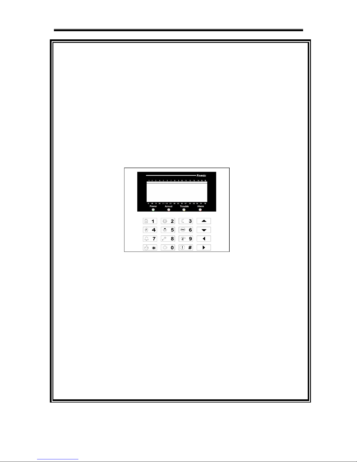
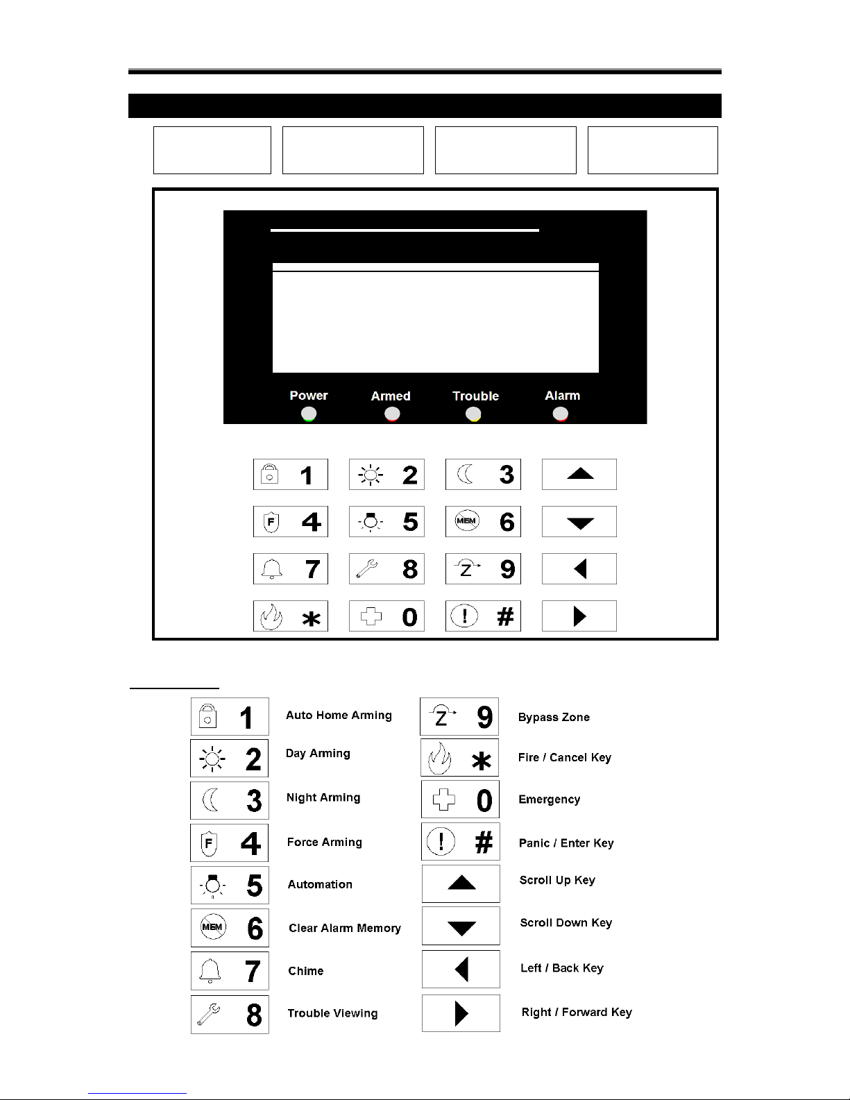
LCD KEYPAD OUTLOOK
Key Indication
POWER:
AC Power light
ARMED:
System arm light
TROUBLE:
System trouble light
ALARM:
System Alarmed
1 2 3 4 5 6 7 8 9 10 11 12 13 14 15 16
17 18 19 20 21 22 23 24 25 26 27 28 29 30 31 32
/ Zone Indicator
/ IO Indicator
/ Volume Control
5

AX1 LCD & ICON User Manual Rev 4.0
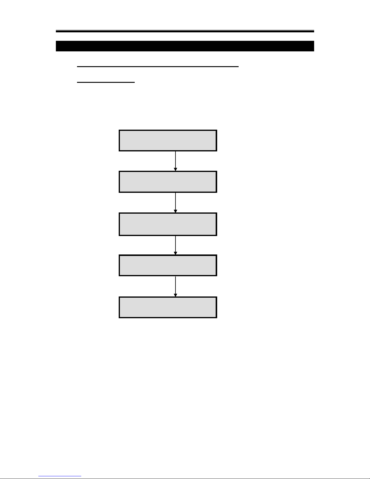
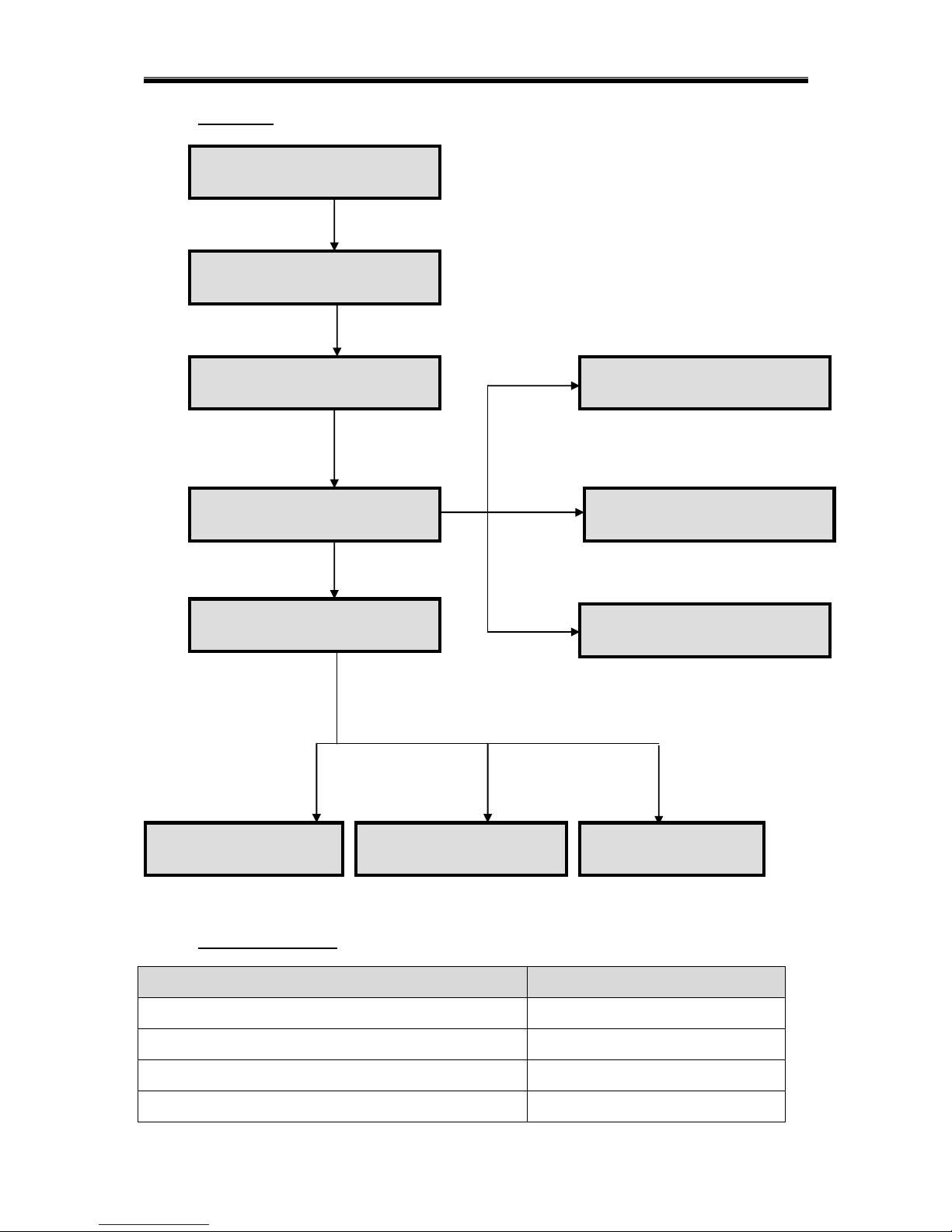
ARMING MODE
ARMING
TYPE
ZONE
STATUS
INFORMATION
WHEN TO
USE
Auto home
Arming
Normal Status
To arm the system with delay time in
order for the user to exit the house
To arm the system in delay time with the
interior zone bypassed provided that the
user does not leave the premises
When user
leaves the house
and no one is at
home.
Day Arming
Normal Status
The perimeter zone is armed instantly
while the user stays at home
The interior zones are automatically
bypassed
When user is at
home.
Force Arming
Normal Status
or
Abnormal
Status
To force arm the system instantly
regardless of the zone status.
The interior zones are not bypassed
When there are
zone still open
& user is at
home.
Night Arming
Normal Status
The perimeter zone is armed instantly
while user stays at home.
The interior zones are automatically
bypassed. The delay zones become instant
zones.
When everyone
come back to
home & user
want to sleep.
NOTE: Zone refers to the designated areas that are protected by the AX1 system. Zone status refers to the
condition of the area. Normal status means door, window or detectors are in good/close condition. While
abnormal status means the door/window may have been opened or the detector is not functioning.
6

AX1 LCD & ICON User Manual Rev 4.0
SOUND INDICATION
Sound Indication
Description
Acceptance / Acknowledgement tone
2 fast beeps
Error tone
Continuous buzz for about 2 seconds
Entry delay
Continuous beep for the delay programmed by
installer.
Exit delay
Continuous beep for the delay programmed by
installer.
Door chime
Continuous tone for about 2 seconds
Alarm
Chirp (1 second ON/ 4 seconds OFF)
Pulse ( 2 seconds ON/ 2 seconds OFF)
Continuous Tone
Silent
LIGHT INDICATION
LED Indication
Description
Power LED
Indicates power supply to keypad.
Armed LED
Indicates system has been armed.
Permanent LED ON when system is fully armed
LED Blinking when system is partially armed
(some partitions are not armed)
Trouble LED
Indicates there are troubles in the system. i.e. AC
loss, Battery loss, External communication error,
Tamper, Short Circuit, Bell Strobe Siren Loss.
Alarmed LED
Indicates there is alarm occurring in the system.
There is a need to clear the alarm memory to clear
this LED.
KEYPAD NAVIGATION KEY FUNCTION
Arrow Up - Scroll Up
Arrow Down - Scroll Down
Arrow Left - Exit to previous menu
Arrow Right - nil
“ # ” Key - Enter
“* ” Key - Exit
7

AX1 LCD & ICON User Manual Rev 4.0
LCD Keypad Overall Menu Tree
1.) ARM
AUTO HOME
o ALL
o PARTITION
PARTITION 1
PARTITION 2
PARTITION 3
PARTITION 4
DAY
o ALL
o PARTITION
PARTITION 1
… PARTITION 4
NIGHT
o ALL
o PARTITION
PARTITION 1
… PARTITION 4
FORCE
o ALL
o PARTITION
PARTITION 1
… PARTITION 4
2.) DISARM
ALL
PARTITION
o PARTITION 1
o PARTITION 2
o PARTITION 3
o PARTITION 4
3.) CLEAR ALARM
4.) BYPASS ZONE
ZONE 1
o ACTIVE / BYPASS
ZONE 2
o ACTIVE / BYPASS
… ZONE 32
o ACTIVE / BYPASS
5.) AUTOMATION
OUTPUT CONTROL
o OUTPUT 1
NO/OFF
o OUTPUT 2
NO/OFF
o … OUTPUT 32
NO/OFF
ON ALL
OFF ALL
8

AX1 LCD & ICON User Manual Rev 4.0
6.) SYSTEM
KEYPAD SETTING
o KEYPAD B/LIGHT
ENABLE / DISABLE
o LCD B/LIGHT
ENABLE / DISABLE
o CHIME
ENABLE / DISABLE
o KEYPRESS TONE
ENABLE / DISABLE
o PRE-WARN TONE
ENABLE / DISABLE
o KEYPAD TAMPER
ENABLE / DISABLE
o FAST KEY
ENABLE / DISABLE
o SPEAKER
ENABLE / DISABLE
o VOLUME CONTROL
o COLOR MODE
BLUE / AMBER
TEST
o WALK TEST
o BELL TEST
o BATTERY TEST
TROUBLES
ZONE STATUS
o ZONE 1
o ZONE 2
o … ZONE 32
PHONE LOSS DET
o ENABLE / DISABLE
7.) USER PROGRAMMING
MASTER
o ENTER NEW PIN
USER
o ADD NEW USER
o DELETE USER
GUEST
o ADD NEW GUEST
o DELETE GUEST
INSTALLER
o INSTALLER ACCESS
ENABLE / DISABLE
TIMER
o ZONE TIMER
ARM TIMER
o SELECT TIMER – TMR1 to TMR4
DAILY
SCHEDULED
DISARM TIMER
o SELECT TIMER – TMR1 to TMR4
DAILY
SCHEDULED
9

AX1 LCD & ICON User Manual Rev 4.0
o OUTPUT TIMER
ON TIMER
o SELECT TIMER – TMR1 to TMR4
DAILY
SCHEDULED
OFF TIMER
o SELECT TIMER – TMR1 to TMR4
DAILY
SCHEDULED
o DATE & TIME
DATE
TIME
DAY
DURESS
o ENTER NEW PIN
8.) ALARM REPORT
9.) PC COMM
WEB ACCESS
o ENABLE / DISABLE
5
10
AX1 LCD & ICON User Manual Rev 4.0
CHAPTER 1: ALARM SYSTEM CONTROL
1.0 ALARM SYSTEM CONTROL USING LCD KEYPAD
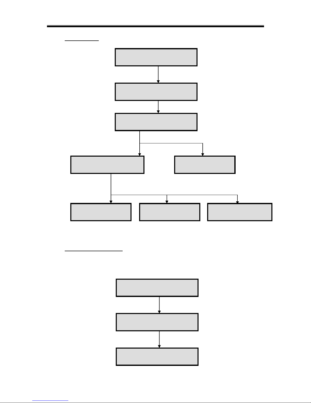
1.0.1 SECURITY MENU
Security menu is a menu that able user to toogle Arm or Disarm by press the partition
number. This menu will show system arming status on the upper line and keypress
description on the bottom line.
Press [User PIN] [#]
to enter security menu
01 - 01 – 2010 Mon
12 : 00
ARMED:
0:ALL 1:P1 2:P2 ►
ARMED: 1 060s
0:ALL 1:P1 2:P2 ►
ARMED:
0:ALL 1:P1 2:P2 ►
Press [1] to arm
partition 1
Press [1] again to
disarm partition 1
Indicator “1” will blink and
exit delay start start to
count down
01 - 01 – 2010 Mon
12 : 00
Press [#] to exit
Security Menu
11
AX1 LCD & ICON User Manual Rev 4.0
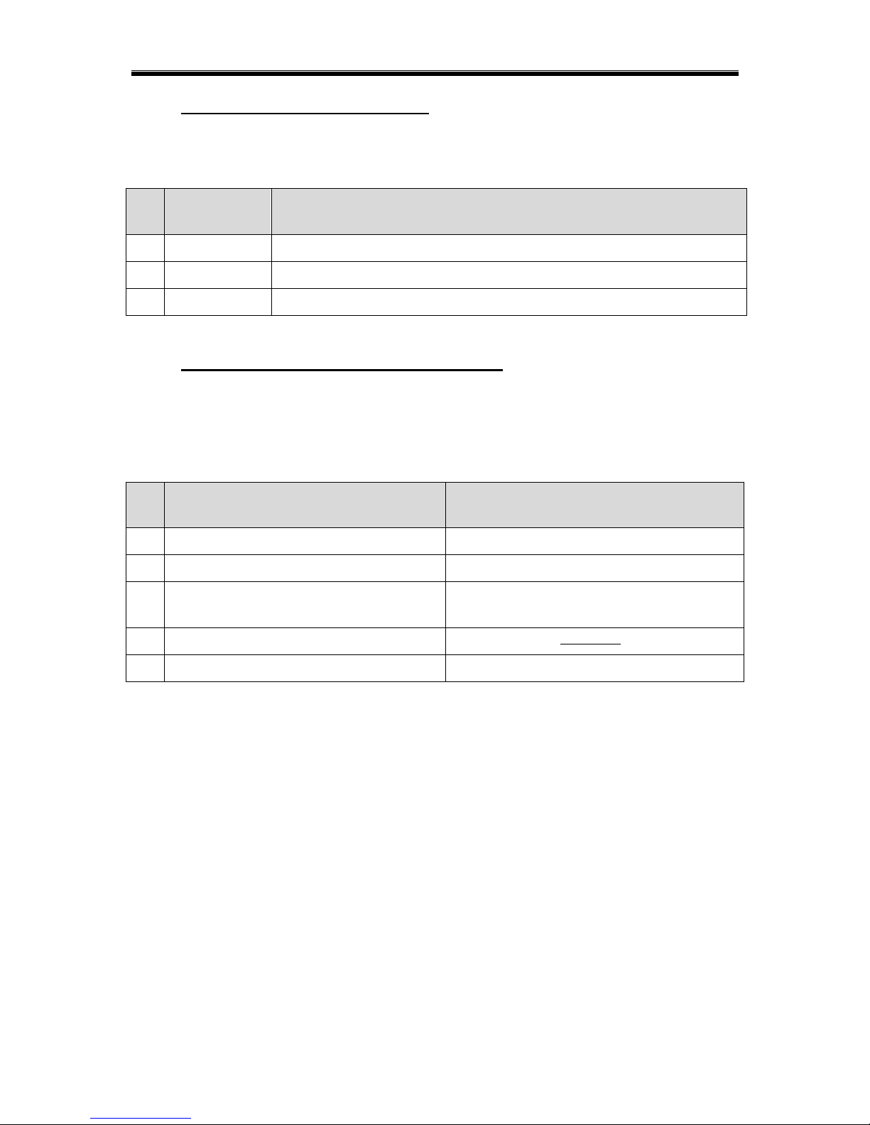
1.0.1.1 ARM / DISARM ALL PARTITION
When [All partition authorized PIN] is use to enter security menu, user will be able to press
[0] to arm / disarm all partition. The control condition is shown in table below:
NO
SYSTEM
STATUS
ACTION WHEN KEY [0] PRESSED IN SECURITY MENU
1
All Arm
System will Disarm all partition
2
Partially Arm
System will Disarm all partition
3
Not Arm
System will Arm all partition
1.0.1.1 ARM / DISARM PARTICULAR PARTITION
In security menu, user can Arm/ Disarm a particular partition by press key [1] / [2] / [3] / [4].
User is not able to control an unauthorized partition. The control condition is shown in table
below:
NO
ACTION WHEN KEY [1]/[2]/[3]/[4]
PRESSED IN SECURITY MENU
DESCRIPTION
1
Partition Arm
Previous status for the partition was disarm
2
Partition Disarm
Previous status for the partition was arm
3
Request Rejected
Partition not available / Partition temporary
not available
4
Request Rejected with open zone name
System is not in full proof condition
5
Unauthorized User
User are not authorized to Arm/Disarm
12

AX1 LCD & ICON User Manual Rev 4.0
Alarm system Control Sub-Menu
1.0.2 ARM
AUTO HOME
o ALL
o PARTITION
PARTITION 1
PARTITION 2
PARTITION 3
PARTITION 4
DAY
o ALL
o PARTITION
PARTITION 1
… PARTITION 4
NIGHT
o ALL
o PARTITION
PARTITION 1
… PARTITION 4
FORCE
o ALL
o PARTITION
PARTITION 1
… PARTITION 4
1.0.3 DISARM
ALL
PARTITION
o PARTITION 1
o PARTITION 2
o PARTITION 3
o PARTITION 4
1.0.4 ALARM REPORT
1.0.5 CLEAR ALARM
1.0.6 BYPASS ZONE
ZONE 1
o ACTIVE / BYPASS
ZONE 2
o ACTIVE / BYPASS
… ZONE 32
1.0.7 ZONE STATUS VIEWING
13
AX1 LCD & ICON User Manual Rev 4.0
1.0.2 ARMING
1.0.2.1 QUICK ARMING
COMMAND
INFORMATION
Press and hold the button [1] for 2 seconds
Auto Home Arming
Press and hold the button [2] for 2 seconds
Day Arming
Press and hold the button [3] for 2 seconds
Night Arming
Press and hold the button [4] for 2 seconds
Force Arming
Press [User PIN] [*]
to enter user menu
01 - 01 – 2010 Mon
12 : 00
ARM
DISARM
Press [#] to ARM
AUTO HOME
DAY
SELECT:
PARTITION 1
Press [▲] or [▼]
to choose types of
Arming Mode
Press [#] to select
Press [▲] or [▼]
to choose
Partition to arm
Press [#] to select
REQUEST REJECTED
SYSTEM IS NOW
ARMED
If partition already armed
or partition‟s zone is
violated for all arming
mode except force arm
If there is no exit
delay, system will
arm instantly
PARTITION
EXIT DELAY
Exit delay starts
to count down
with sound
14
ALL
PARTITION
If PARTITION is
selected
If ALL is selected,
System OK and
without exit delay
SYSTEM IS NOW
ARMED
REQUEST
REJECTED
PARTITION
EXIT DELAY ***S
If ALL is selected,
and system is not
OK
If ALL is selected,
System OK and
with exit delay
AX1 LCD & ICON User Manual Rev 4.0
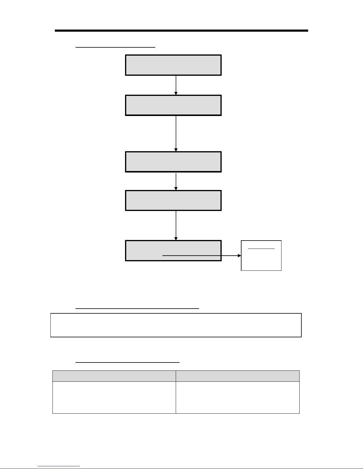
1.0.3 DISARMING
1.0.4 ALARM REPORTING
When alarm occurs, the strobe lights and the bells will be turned on. If the system is disarmed, it
could only turn off the bell but not the strobe light. At the moment, the User can trace back which
zone has been violated previously.
Press [User PIN] [*]
to enter user menu
01 - 01 – 2010 Mon
12 : 00
USER PROGRAM
ALARM REPORT
Press [#]
ZONE 01
Press [#] to
DISARM
System is now
disarm
Press [User PIN] [*]
to enter user menu
01 - 01 – 2010 Mon
12 : 00
ARM
DISARM
ALL
PARTITION
SELECT:
PARTITION 1
Press [▼] or [▲]
to choose to disarm all
or by partition
Press [#] to select
Press [▼] or [▲]
to choose
Partition to disarm
Press [#] to select
If „ALL‟ is selected
SYSTEM IS NOW
DISARM
PARTITION IS NOW
DISARMED
PARTITION NOT
ARM
Partition is not
armed – partition
cannot be disarmed
REQUEST REJECTED
This partition does
not exists
15
AX1 LCD & ICON User Manual Rev 4.0
1.0.5 CLEAR ALARM MEMORY
When alarm occurs, the strobe lights and the bells will be turned on. If the system is disarmed, it
could only turn off the bell but not the strobe light. Thus, the user needs to clear the alarm memory to
turn off the strobe light. Besides that, once the alarm memory is cleared, the auxiliary power supply 1
will be reset for 3 seconds before restoring it again.
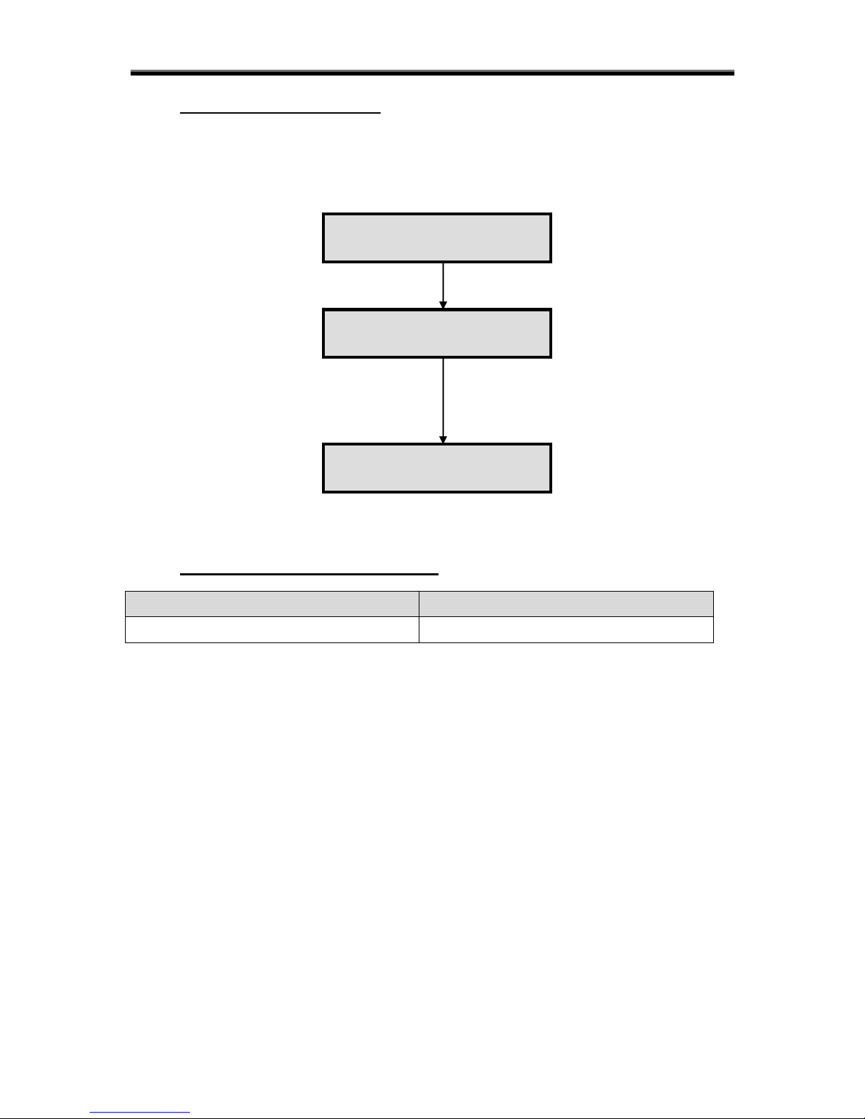
1.0.5.1 QUICK CLEAR ALARM MEMORY
COMMAND
INFORMATION
Press and hold the button [6] for 2 seconds
Clear alarm memory
Press [▼] or [▲]
to choose
„CLEAR ALARM‟
from main menu
Press [#] to select
Press [User PIN] [*]
to enter user menu
01 - 01 – 2010 Mon
12 : 00
CLEAR ALARM
BYPASS
ALARM CLEARED
16
AX1 LCD & ICON User Manual Rev 4.0
1.0.6 BYPASSING ZONE
Bypassing a zone means removal of one or more protection zones from the system. In order to
perform bypassing, the system must be in normal mode. Once the system is disarmed, all the zone
will be unbypassed.
1.0.6.1 QUICK VIEW ON BYPASS DESCRIPTION
1.0.6.2 QUICK BYPASSING ZONE
COMMAND
INFORMATION
Press and hold the button [9] for 2 seconds
Bypassing zone
Press [▼] or [▲]
to choose „BYPASS‟
from main menu
Press [#] to select
Press [#] to toggle the
current zone status from
active to bypassed
Press [▼] or [▲]
to choose next zone.
Press [*] to return to
main menu
Press [User PIN] [*]
to enter user menu
01 - 01 – 2010 Mon
12 : 00
CLEAR ALARM
BYPASS
ZONE 1
- ACTIVE
ZONE 1
- BYPASS
ZONE 2
- ACTIVE
17
Once at desired zone in ZONE STATUS menu, press “0” to view the zone description that have
been predetermine during installation using the voice setting.
Bypass zones are cleared after system is disarmed.
It can be done by pressing [#] in bypass menu until the ACTIVE status is shown.
AX1 LCD & ICON User Manual Rev 4.0
Press [▼] or [▲] to
select other zones or
press [*] to return to
main menu.
01 - 01 – 2010 Mon
12 : 00
AUTOMATION
SYSTEM
Press [▼] or [▲]
to choose
„SYSTEM‟
from main menu
Press [#] to select
TROUBLES
ZONE STATUS
SELECT
ZONE 01
Press [▼] or [▲]
to choose zone.
Press [*] to return to
main menu
ZONE 2
- NORMAL
Other status
Violated
Bypass
Alarm
1.0.7 ZONE STATUS VIEWING
1.0.7.1 QUICK VIEW ON ZONE DESCRIPTION
1.0.7.2 QUICK ZONE STATUS VIEWING
COMMAND
INFORMATION
Press and hold the button [▲] for 2 seconds
Zone 1-32 status
O: Normal (Zone is OK)
X: Violated (Zone is OPEN)
Press [MASTER PIN] [*]
to enter master menu
Press [#] to enter zone
status.
Once at desired zone in ZONE STATUS menu, press “0” to view the zone description that have
been predetermine during installation using the voice setting.
18
Top Row [Zone 1 to 16] starting from left to right
Bottom Row [Zone 17 to 32] starting from left to right

AX1 LCD & ICON User Manual Rev 4.0
CHAPTER 2: HOME AUTOMATION CONTROL
2.0 INTRODUCTION
The system can support up to 32 outputs. The outputs can be electrical appliances such as airconditioners, fans or lights. The outputs can be configured as event-triggered outputs or
normal outputs which are controlled either by LCD keypad, real time clock timer or
telephone remote control.
Recommended air conditioner with memory backup or last state memory in Malaysia is as
below:
1. Wall Mounted Split Air Conditioner (Brand : Acson)
Model: AWM101 – (1.0 HP)
AWM151 – (1.5 HP)
AWM201 – (2.0 HP)
AWM251 – (2.5 HP)
AWM301 – (3.0 HP)
2. Ceiling Cassette Split Air Conditioner (Brand : Acson)
Model: ACK15B – (1.5 HP)
ACK20B – (2.0 HP)
ACK25B – (2.5 HP)
ACK30B – (3.0 HP)
Automation Control Sub-Menu
1) AUTOMATION
OUTPUT CONTROL
o OUTPUT 1
o OUTPUT 2
o OUTPUT 3
o OUTPUT 4
o … OUTPUT 32
ON ALL
OFF ALL
19
AX1 LCD & ICON User Manual Rev 4.0
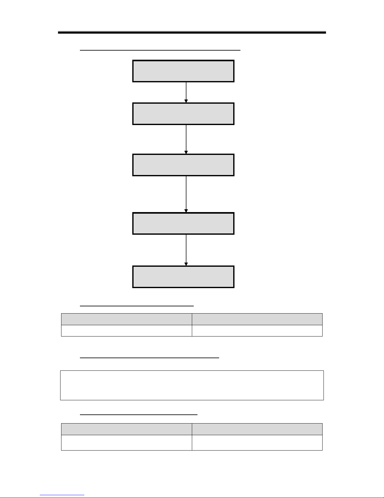
2.1 AUTOMATION CONTROL USING LCD KEYPAD
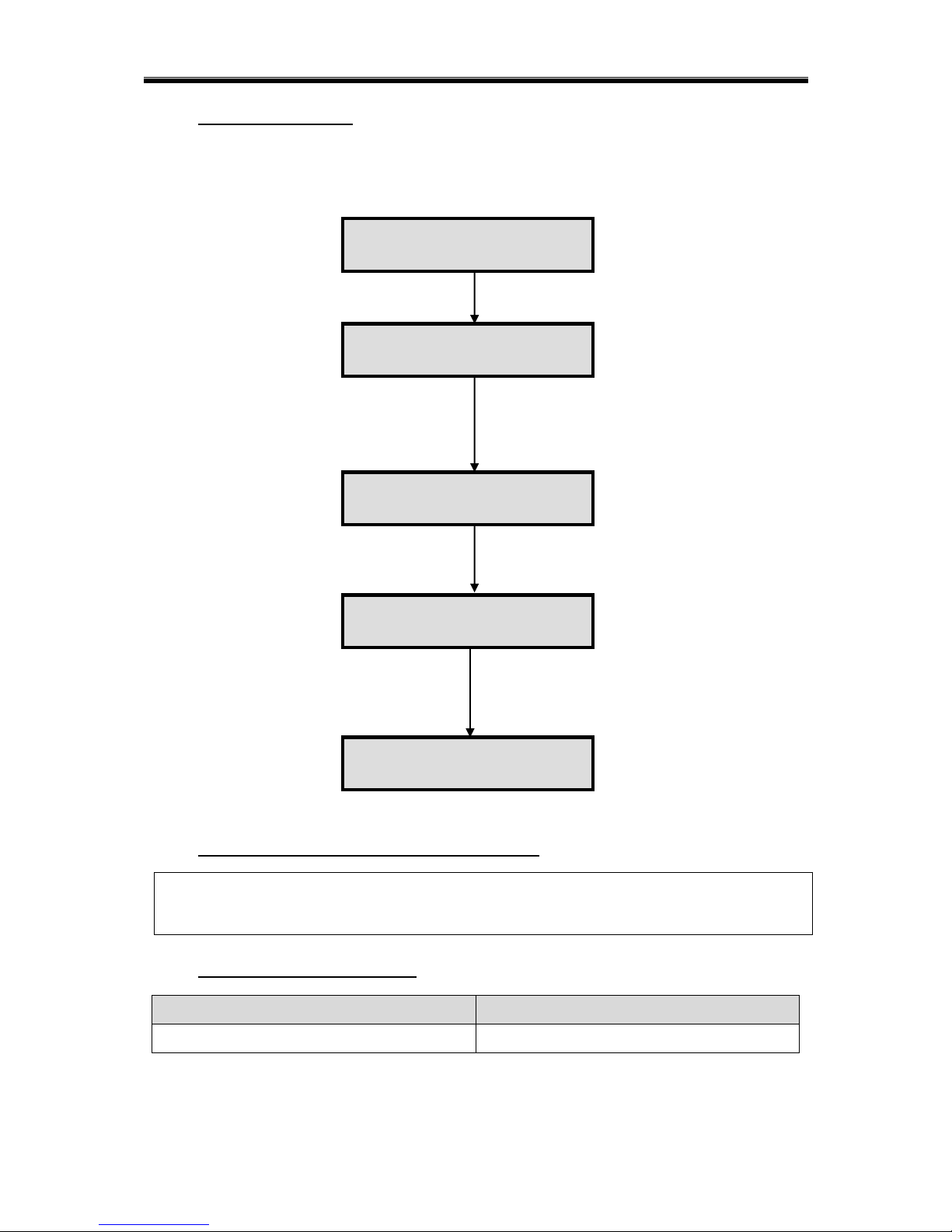
2.1.1 QUICK AUTOMATION CONTROL
COMMAND
INFORMATION
Press and hold the button [5] for 2 seconds
Automation control
2.1.2 QUICK VIEW OF OUTPUT DESCRIPTION
Once at desired output, just press “0” to view the output description that have been
predetermine during installation using the voice setting.
2.1.3 QUICK VIEW OF OUTPUT STATUS
COMMAND
INFORMATION
Press and hold the button [▼] for 2 seconds
Output status 1-32.
O: On, X: Off, Blank: No output
20
Top Row [Output 1 to 16] starting from left to right
Bottom Row [Output 17 to 32] starting from left to right
Press [▼] or [▲] to choose
„AUTOMATION‟ from main menu
Press [#] to select.
Press [#] to toggle the output
If „ON‟, the output will turn „OFF‟ if [#] is pressed
If „OFF‟, the output will turn „ON‟ if [#] is pressed
Press [*] to return to main menu
Press [User PIN] [*]
to enter user menu
01 - 01 – 2010 Mon
12 : 00
OUTPUT 1
- ON
OUTPUT 1
- OFF
OUTPUT CONTROL
ON ALL
Output control to on/ off IO one by one.
ON ALL or OFF ALL to control all.
AUTOMATION
SYSTEM

AX1 LCD & ICON User Manual Rev 4.0
CHAPTER 3: USER PROGRAMMING
3.0 USER SETTING EDIT
Only the user who has the Master PIN can access the user-programming mode. Once the
user goes into user programming mode, user can access to the following options:
USER PROGRAMMING SUB-MENU
1) USER PROGRAMMING
MASTER
o ENTER NEW PIN
USER
o ADD NEW USER
o DELETE USER
GUEST
o ADD NEW GUEST
o DELETE GUEST
INSTALLER
o INSTALLER ACCESS
ENABLE / DISABLE
TIMER
o ZONE TIMER
ARM TIMER
o SELECT TIMER – TMR1 to TMR4
DAILY
SCHEDULED
DISARM TIMER
o SELECT TIMER – TMR1 to TMR4
DAILY
SCHEDULED
o OUTPUT TIMER
ON TIMER
o SELECT TIMER – TMR1 to TMR4
DAILY
SCHEDULED
OFF TIMER
o SELECT TIMER – TMR1 to TMR4
DAILY
SCHEDULED
o DATE & TIME
DATE
TIME
DAY
DURESS
o ENTER NEW PIN
21
 Loading...