

Oyen Digital RS-M4T User Manual
1

TABLE OF CONTENTS
GENERAL INFORMATION...................................................................................................................... 4
COPYRIGHT ................................................................................................................................................ 4
NOTICES AND CLASSIFICATIONS ................................................................................................................ 4
CONTACT US.............................................................................................................................................. 4
PRECAUTIONS FOR THE RAID SYSTEM............................................................................................ 5
GENERAL PRECAUTIONS............................................................................................................................. 5
RAID SYSTEM PRECAUTIONS .................................................................................................................... 5
INTRODUCTION........................................................................................................................................ 6
FEATURES................................................................................................................................................... 6
SYSTEM REQUIREMENT.............................................................................................................................. 7
OPTIONAL ACCESSORIES ............................................................................................................................ 7
PACKAGE CONTENTS.................................................................................................................................. 8
SYSTEM VIEWS......................................................................................................................................... 9
FRONT VIEW............................................................................................................................................... 9
REAR VIEW ................................................................................................................................................ 9
TOP & COVER VIEW (EXPOSED)................................................................................................................10
INSERTING/REPLACING THE HARD DRIVES IN THE RAID SYSTEM......................................11
FASTEN THE HDD SMARTGUIDER KIT ONTO THE HARD DRIVE ..............................................................12
PLACE THE HDD SMARTGUIDER KIT INSIDE THE RAID SYSTEM ............................................................15
CONNECTING THE RAID SYSTEM TO A HOST COMPUTER.......................................................17
NUMBER OF HARD DRIVE/SSD SUPPORTING EACH RAID MODE............................................19
DISK SLOT NUMBER...............................................................................................................................19
LED INDICATORS....................................................................................................................................20
GREEN: ON / OFF.......................................................................................................................................20
RED: ON / BLINK / FLASH ..........................................................................................................................20
WHITE: ON / FLASH...................................................................................................................................20
ALL DISKS: INSERTED / DETECTED............................................................................................................21
ALL DISKS: NOT INSERTED / DETECTED...................................................................................................21
ALL DISKS: DISK 4 DATA ACCESS ONLY.................................................................................................21
ALL DISKS: DISK 4 ERROR ONLY............................................................................................................21
ALL DISKS: DISK 4 REBUILD ONLY.........................................................................................................21
FAN: ERROR ..............................................................................................................................................21
DAISY CHAIN: CONNECTING MULTIPLE DEVICES......................................................................22
SAFE REMOVAL OF THE RAID SYSTEM...........................................................................................22
SSD SMARTGUIDER KIT........................................................................................................................23
SSD SMARTGUIDER KIT: PACKAGE.....................................................................................................23
SSD SMARTGUIDER KIT: SSD COMPATIBILITY...................................................................................23
SSD SMARTGUIDER KIT: INSTALLATION.............................................................................................24
RAID MASTER FOR MAC.......................................................................................................................26
RAID MASTER: INSTALLATION..........................................................................................................26
INSTALLATION FOR MAC.................................................................................................................26
RAID MASTER: GUI.................................................................................................................................30
2

INFORMATION:...................................................................................................................30
CONFIGURATIONS:............................................................................................................30
SETTINGS:............................................................................................................................30
NOTIFICATIONS:.................................................................................................................30
LOGS:....................................................................................................................................30
FIRMWARE:..........................................................................................................................30
RAID MASTER: FEATURES...................................................................................................................31
INFORMATION......................................................................................................................................31
DEVICE INFORMATION:....................................................................................................31
RAID & DISK INFORMATION:...........................................................................................31
DISK INFORMATION: .........................................................................................................32
RAID CONFIGURATIONS:....................................................................................................................33
SETTINGS:..............................................................................................................................................33
NOTIFICATIONS:...................................................................................................................................34
EVENT LOG:...........................................................................................................................................34
FIRMWARE INFORMATION................................................................................................................35
RAID MASTER: OPERATION................................................................................................................36
RAID CONFIGURATIONS: SET UP A NEW RAID SET ......................................................................36
RAID CONFIGURATIONS: DELETE AN EXISTING RAID SET........................................................39
RAID CONFIGURATIONS: REBUILD A RAID SET............................................................................41
WINDOWS OS: PLUG AND PLAY DRIVER.........................................................................................44
PLUG AND PLAY DRIVER: INSTALLATION.....................................................................................44
MARVELL STORAGE UTILITY (MSU) FOR WINDOWS.................................................................47
MSU INSTALLATION...............................................................................................................................47
LED INDICATORS .................................................................................................................................48
POWER LED x 1..................................................................................................................................48
RAID ALERT LED x 1.........................................................................................................................48
DISK LED x 8......................................................................................................................................48
RAID MASTER .......................................................................................................................................49
POPUP WINDOWS.............................................................................................................................49
REBUILD.................................................................................................................................................51
RAID MODES..........................................................................................................................................51
RAID 0 (Striping).................................................................................................................................52
RAID 1 (Mirroring)..............................................................................................................................52
RAID 1+0.............................................................................................................................................53
JBOD (None RAID).............................................................................................................................53
HYPERDUO (Capacity and Safe)........................................................................................................54
APPENDIX: SPECIFICATIONS..............................................................................................................55
3

GENERAL INFORMATION
Copyright
V10 Copyright © 2013 Data Watch Technologies Co., Ltd. All rights reserved.
DataTale and DataTale logo are the trademarks of Data Watch Technologies Co.,
Ltd. No part of DataTale brand products and materials may be reproduced,
stored in a retrieval system, or transmitted in any form or by any means
(electronic, mechanical, photocopying, recording or otherwise), without the prior
written consent of Data Watch Technologies Co., Ltd. Thunderbolt
Thunderbolt
other countries.
The product information provided in this user’s manual is subject to change
without prior notice and does not represent a commitment on behalf of the
vendor. The vendor assumes no liability or responsibility for any errors that may
appear in this manual. Firmware, software, images, and descriptions may vary
slightly from actual products.
TM
logo are trademarks of Intel Corporation in the United States and
Notices And Classifications
FCC-B Radio Frequency Interference Statement
This device complies with Part 15 of the FCC rules. Operation is subject to the
following two conditions:
This device may not cause harmful interference.
This device must accept any interference received, including interference that
may cause undesired operation.
This equipment has been tested and found to comply with the limits for a Class
B digital device, pursuant to Part 15 of the FCC rules. These limits are designed
to provide reasonable protection against harmful interference when the
equipment is operated in a commercial environment. This equipment generates
uses and can radiate radio frequency energy and, if not installed and used in
accordance with the instruction manual, may cause harmful interference to radio
communications.
TM
and the
Contact Us
We are committed to offer economical, high-quality connectivity and storage
enclosure solutions to the market. Any questions, inquiries or comments are
highly welcomed. For the latest version of the User Manual & Technical Support,
please go to our website at www.datawatchtech.com
quality service, please complete the Product Registration on our website.
Data Watch Technologies Co., Ltd.
3F, No. 60, Lane 321, Yang Guang St., Nei Hu, Taipei 114 Taiwan
Tel: +886-2-8797-8868 Fax: +886-2-8797-4801
Email: info@datawatchtech.com
4
. To enhance excellent

PRECAUTIONS FOR THE RAID SYSTEM
General Precautions
The main circuit board of the RAID System is susceptible to static
electricity. Proper grounding is required to prevent electrical
damage to the RAID System or other connected devices, including
the host computer. Always place the RAID System on a smooth
surface and avoid all dramatic movement, vibration and percussion.
Do NOT place the RAID System close to magnetic devices (such
as a mobile phone), high-voltage devices (such as a hair dryer), or
near a heat source (such as on the dashboard of a car or any place
where it will be exposed to direct sunlight).
Use only the power supply cable provided with the RAID System.
Do NOT attempt to service this RAID System yourself. Please
contact Technical Support in regards to any parts other than the
ones already mentioned in the Installation Section of this User’s
Manual.
Do NOT block the ventilation. Proper airflow is required to ensure
reliable operation and to prevent overheating.
Do NOT allow water to enter the RAID System.
Do unplug the RAID System from the electrical outlet when not in
use to provide an ecological friendly environment.
RAID System Precautions
Installation of RAID MASTER software in the host computer is
required for proper operation.
Installation of additional equipment in the host computer may be
required. Visit our website at www.datawatchtech.com
the latest product information updates.
Any loss, corruption, or destruction of data is the sole
responsibility of the user of the RAID System. Under no
circumstances will the manufacturer be held liable for the
recovery or restoration of any data.
to download
5

INTRODUCTION
Thank you for purchasing the DataTale SMART 4-Bay Thunderbolt
TM
System. The RAID System with Thunderbolt
connection and RAID MASTER
TM
RAID
(Graphic User Interface) provides up to 10Gbps of access/transfer speeds along
with substantial storage capacity and distinctive RAID configuration options in a
desktop storage device. The RAID MASTER allows easy configuration of RAID
Modes: JBOD (None RAID), RAID 0 (Striping), RAID 1 (Mirroring), RAID 1+0,
and HyperDuo (Capacity/Safe).
Please thoroughly read and follow the instructions provided in this manual.
Failure to do so may result in damage to the RAID System, and any or all of the
connected devices.
Features
Compatible with SATA hard drives and solid-state drives, up to 6 Gbps
Connects via two (2) Thunderbolt
Provides multiple RAID tasks for effective storage management: JBOD
(None RAID), RAID 0 (Striping), RAID 1 (Mirroring), RAID 1+0, and
HyperDuo (Capacity/Safe)
Compatible with Disk Utility (Apple) and configurable as a “Fusion Drive”
Supports Rebuild under RAID 1, RAID 1+0, and HyperDuo (Safe Only)
Compatible with Time Machine (Apple) for backups & file protection
Provides multiple devices with increased speed and flexibility via Daisy
Chain (Up to six Thunderbolt
Configures RAID modes easily using RAID MASTER (GUI)
Monitors System status via LED indicators or RAID MASTER (GUI)
Features effortless yet trayless hard drive/SSD hot swap or hot plug via
SmartGuider*
Dissipates heat efficiently with aluminum housing
Maximizes airflow with two silent fans, SmartGuider* design, and well-
matched mechanical design
Latest support and trouble-shooting information can be found on our website.
SmartGuider is a trayless device that utilizes the simplicity of a handle and
screws. The integrated handle is attached onto the hard drive (or SSD inside a
SSD Bracket) with auto-limiting segmented screws. Then, the entire HDD/SSD
SmartGuider Kit can be slide into the RAID System by aligning the screws with
its specially designed guides. This enables flexibility for easy hard drive/SSD
removal and insertion.
TM
ports (up to 10Gbps of transfer rates)
TM
-compatible devices/displays)
6

System Requirement
To use the RAID System, the minimum system configuration in the host
computer requires the following:
1G of RAM or higher
Mac OS X 10.7 or higher
Windows Vista, 7, 8, or Windows Server 2008
Chrome 18, FireFox 11, Safari 5.1, Opera 11.61, IE 9 or higher
One available ThunderboltTM port
Install appropriate Driver first before using under Windows, please go to the
Chapter “Windows OS: Plug & Play Driver” for reference.
3.5/2.5-inch SATA-compatible hard drive and/or 2.5-inch SSD are required for
the RAID System. Once the hard drive and/or SSD are formatted, the actual
available storage capacity can vary depending on the selected operating
environment (normally 5-10 % less).
Optional Accessories
SSD SmartGuider Kit (Retail package sold separately)
ThunderboltTM Cable (check your dealer to see if it is included in the
package or sold separately)
Due to restrictions of each individual SSD's controller and user's host system,
not all the SSDs are compatible when utilized with the RAID System. Please see
SSD SmartGuider Kit Section for more information.
7
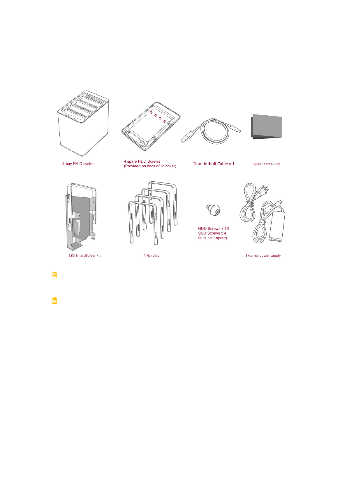
Package Contents
Please keep all package contents and packaging material in the event that the
product must be returned.
Please go to our websites for the most updated information and resources,
including RAID MASTER and User’s Manual. http://www.data-tale.com;
http://www.datawatchtech.com
8
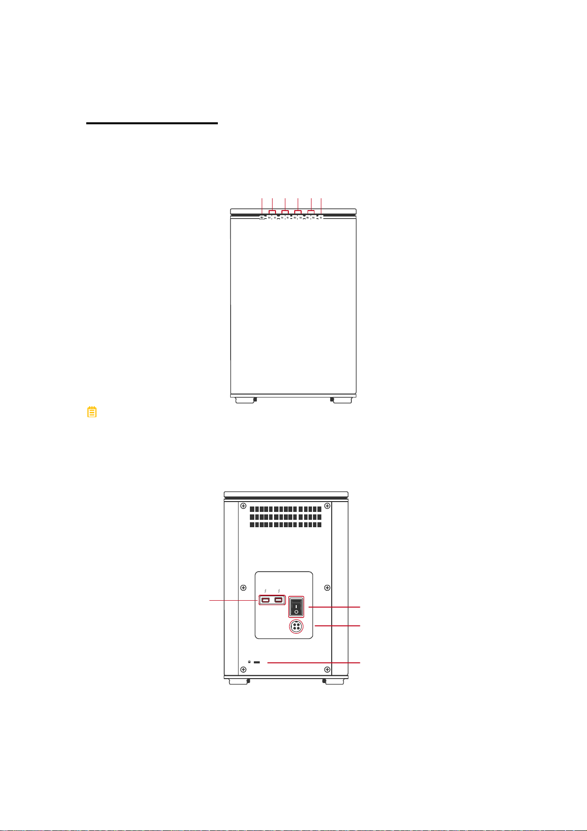
SYSTEM VIEWS
t
Front View
Disk 4
Power
Disk 3
Disk 2
Disk 1
RAID Alert
The status indication of each LED indicator is listed under the LED
INDICATORS section.
Rear View
Thunderbolt
Port
Power Switch
DC IN
DC IN
Lock Port / Slo
9
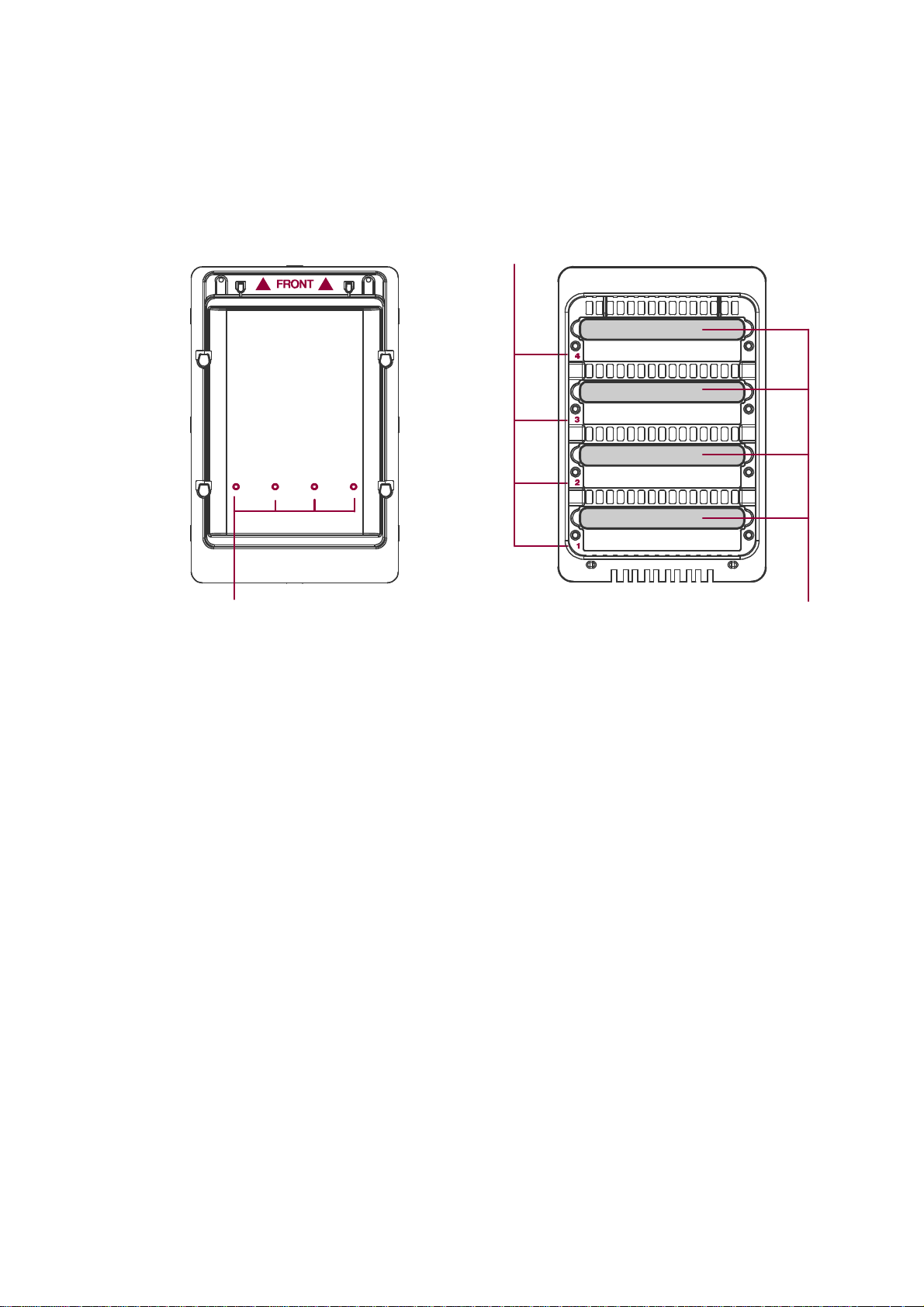
Top & Cover View (Exposed)
Disk Slots (indicate Disk1 through Disk 4)
4 Spare HDD Screws
Handles
10
INSERTING/REPLACING THE HARD DRIVES IN
THE RAID SYSTEM
To assemble the RAID System, please follow the steps listed in the instructions
below:
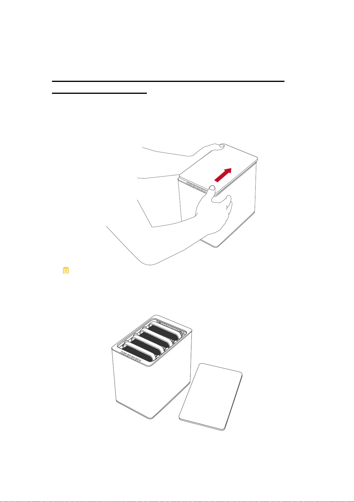
1. Place the RAID System with its Front View facing you. Position both hands
on the top lid, one in the front and one in the back. Simultaneously, push the
lid in the direction away from you, front to back, using your thumbs.
A “click” sound would indicate release of the top lid’s security clasp.
2. Lift the top lid up to remove and expose the Top View (or Disk Slots).
Remove the Handles from the RAID System itself and locate the HDD Screws
in the packaging box.
11
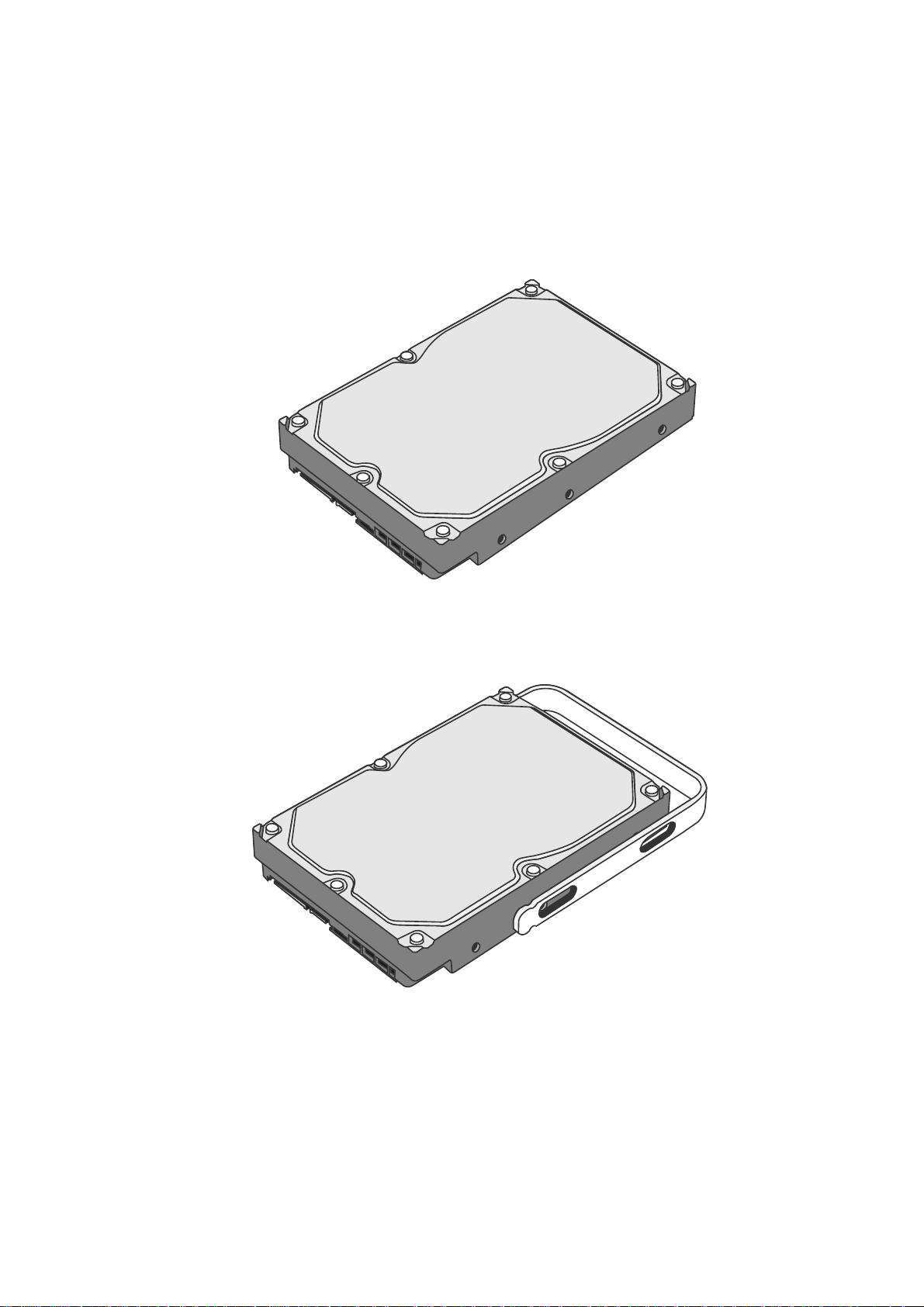
Fasten The HDD SmartGuider Kit Onto The Hard Drive
3. Place the hard drive with the metal cover side facing up and ensure that the
interface connectors are oriented toward your left side.
Connectors
4. Position the Handle to the hard drive end, which is facing away from the
interface connectors, and align it with the HDD Screw hole openings.
Connectors
12
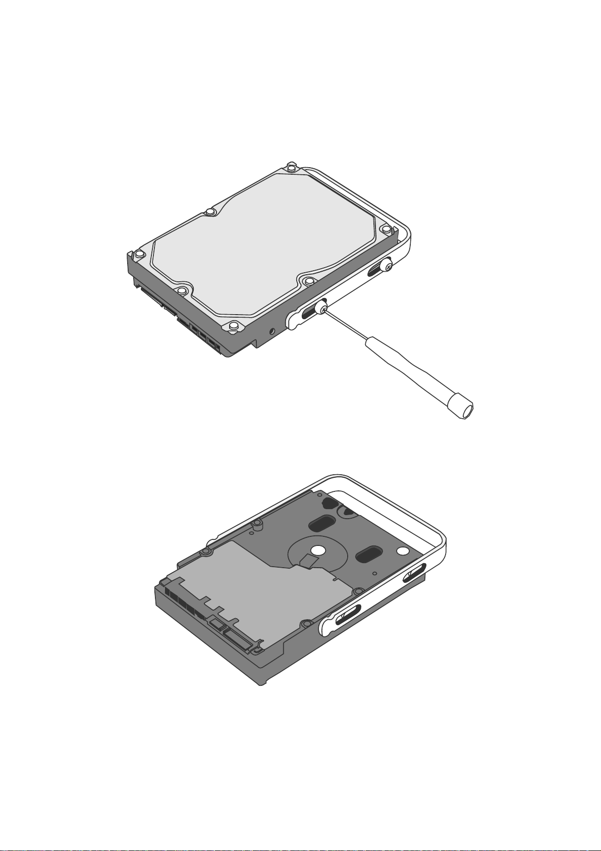
5. Fasten the Handle onto the hard drive by inserting and tightening the HDD
Screws, the left one first, then the right one.
Right
Left
6. Now, flip the hard drive so it is facing you with the PCBA (Printed Circuit
Board) on top and the unfasten Handle side facing you.
13
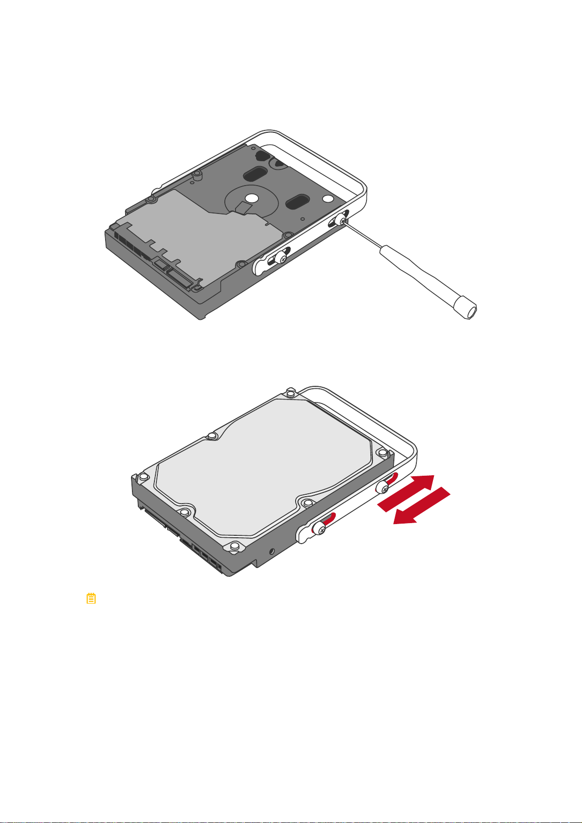
7. Insert and tighten the HDD Screws, the left one first, then the right one.
Right
Left
8. Finally, test sliding the Handle to make sure that the holes glide smoothly on
the HDD Screw guides and the HDD SmartGuider Kit is completed! Repeat
the same procedures for rest of the hard drive(s) if necessary.
The auto-limiting segmented screws are designed to prevent the hard drives
or/and the handles from damages due to over-tightening. Furthermore, this
design makes the handle slide easily without any tightness.
14
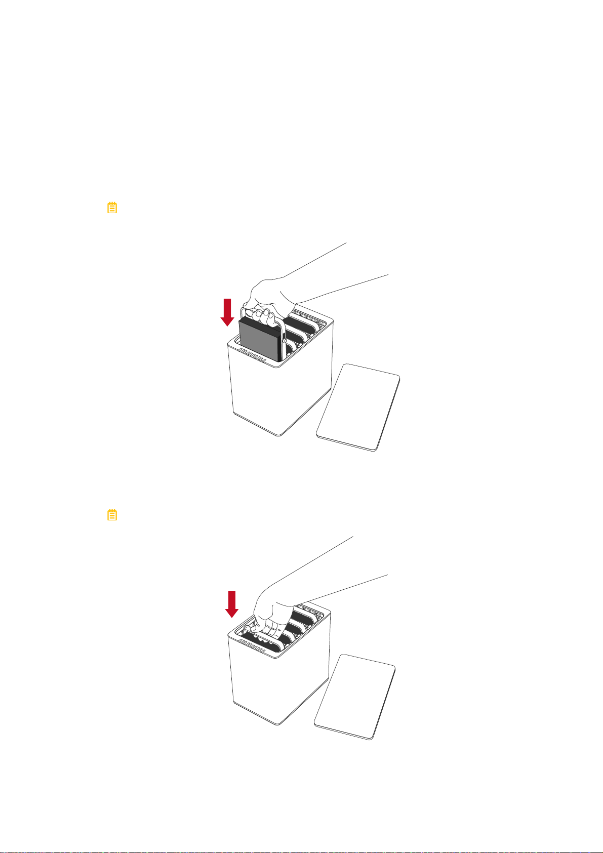
Place The HDD SmartGuider Kit Inside The RAID System
9. Hold the HDD SmartGuider Kit with its metal cover side facing you and the
Handle attached in the upward position.
If the HDD SmartGuider Kit is inserted on its reverse side, the SmartGuider
System would not be able to align and the HDD SmartGuider Kit cannot be
inserted.
10. Align the Handle with the guide rails and slide the HDD SmartGuider Kit into
the indicated Disk Slot. Firmly push downward until a “thump” sound is heard.
Repeat the same procedures for rest of the HDD SmartGuider Kit(s).
In most cases, you would need to firmly push the HDD SmartGuider Kit to
a close until a “thump” sound is heard.
15
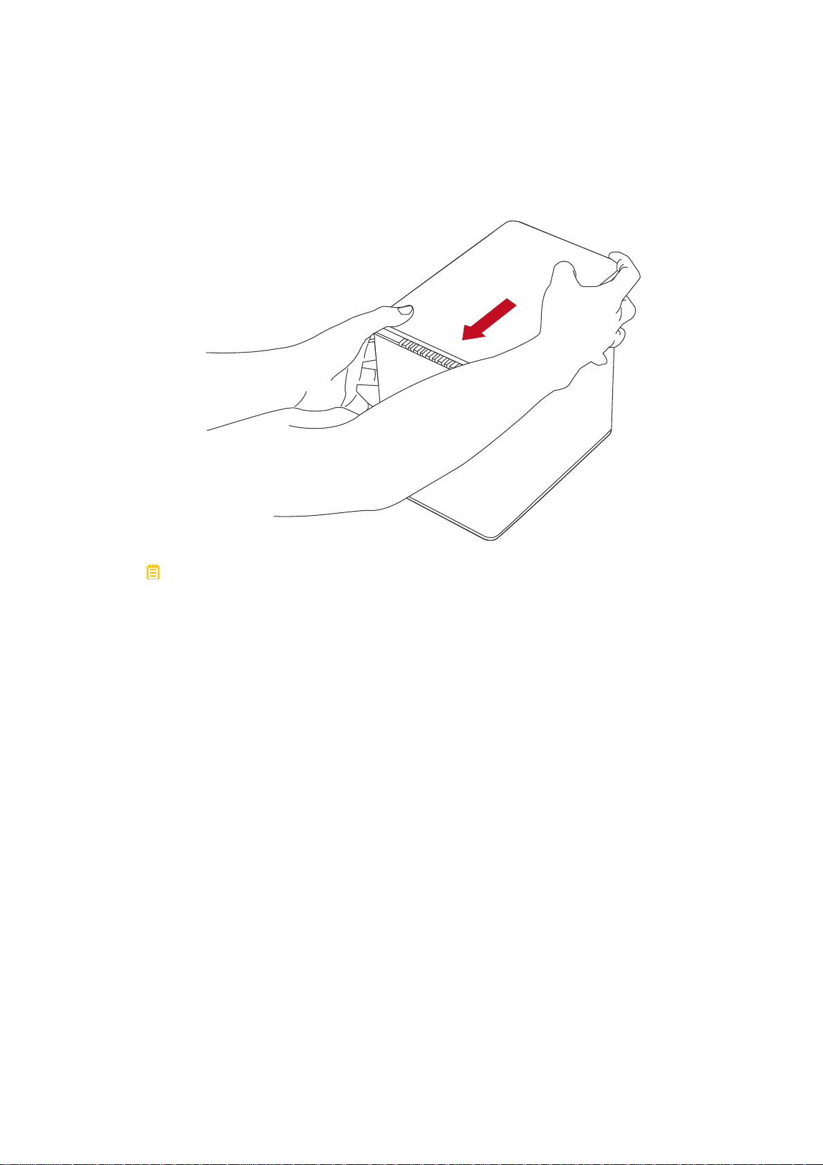
11. Place the RAID System with its Front View facing you and the top lid on.
Position both hands on the top lid, one in the front and one in the back.
Simultaneously, push the lid firmly downward and toward you, back to front.
A “click” sound would indicate grasp of the top lid security clasp.
16
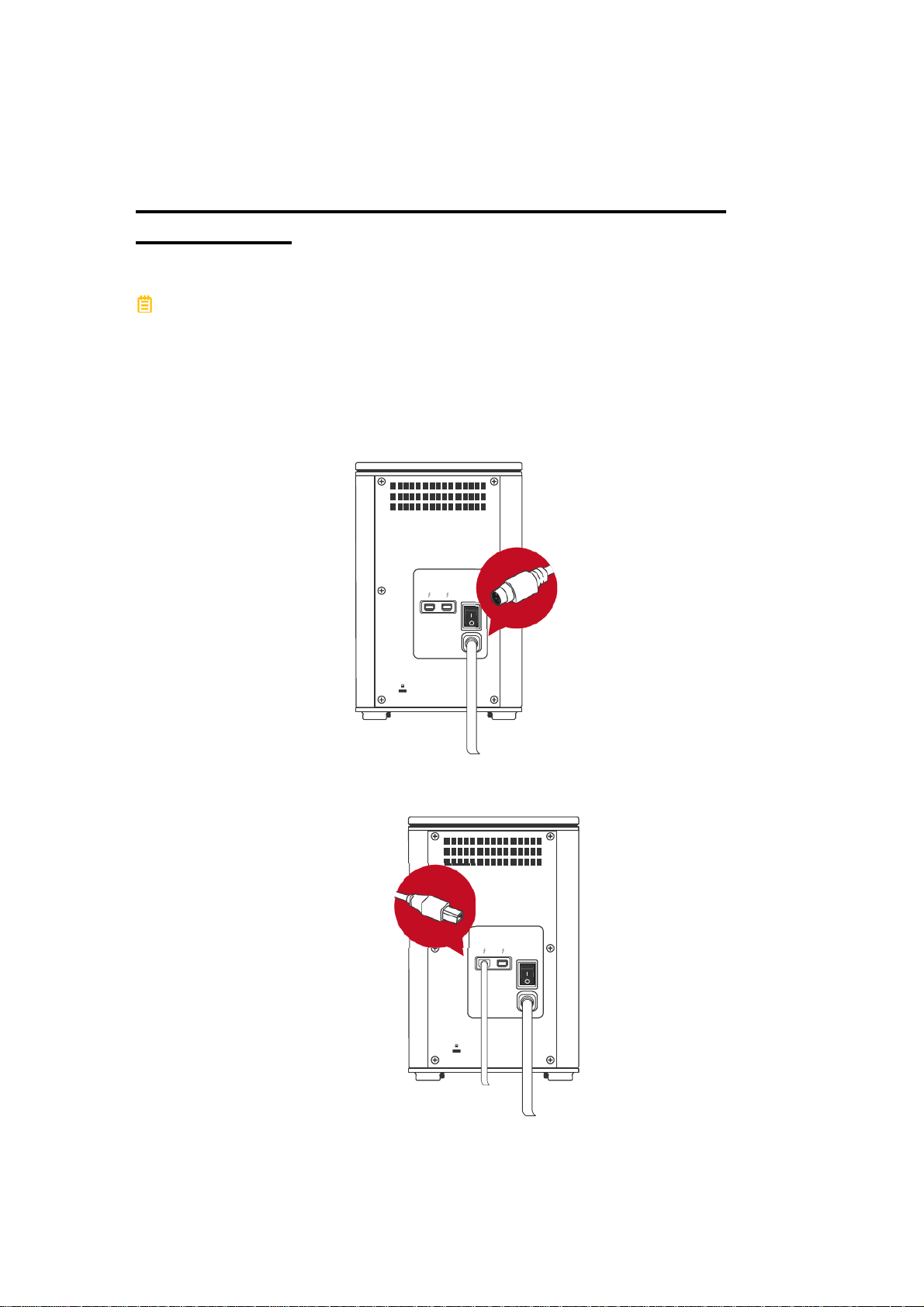
CONNECTING THE RAID SYSTEM TO A HOST
COMPUTER
To connect the RAID System, please complete the following steps:
The ThunderboltTM technology is designed to control power supply/energysaving and time management between the host computer and connected
Thunderbolt
and the Thunderbolt
the RAID System can be powered “ON”.
1. First, connect the AC/DC Power Adapter (External Power Supply).
TM
-compatible devices. Therefore, both the External Power Supply
TM
Cable need to be connected with the RAID System before
DC IN
2. Then, insert both ends of the Thunderbolt
port of the RAID System and the host computer.
17
TM
Cable(s) into the corresponding
DC IN
 Loading...