

Instruction Manual
revision 1

INDEX
Chapter 1 - Specifications .....................................................................................................................................................................................................................................................................................
Chapter 2 - Important Notes ....................................................................................................................................................................................................................................................................................
Chapter 3 - Required Tools for Assembly ...............................................................................................................................................................................................................................................................
Chapter 4 - What's Inside The Box .........................................................................................................................................................................................................................................................................
Chapter 5 - Pinion Selection & RPM .......................................................................................................................................................................................................................................................................
Chapter 6 - Tail Assembly .......................................................................................................................................................................................................................................................................................
Chapter 7 - Main Frame Assembly .........................................................................................................................................................................................................................................................................
Chapter 8 - Align and Lock Frame Panel ................................................................................................................................................................................................................................................................
Chapter 9 - Transmission Assembly .......................................................................................................................................................................................................................................................................
Chapter 10 - Belt Tension & Adjustment .................................................................................................................................................................................................................................................................
Chapter 11 - Main Rotor Assembly .........................................................................................................................................................................................................................................................................
Chapter 12 - ESC Installation .................................................................................................................................................................................................................................................................................
Chapter 13 - Flybarless Installation ........................................................................................................................................................................................................................................................................
Chapter 14 - Servo & Servo Rod Prepareration .....................................................................................................................................................................................................................................................
Chapter 15 - Cylic Servo Installation ......................................................................................................................................................................................................................................................................
Chapter 16 - Tail Servo Installation ........................................................................................................................................................................................................................................................................
Chapter 17 - Landing Gear & Battery Installation ...................................................................................................................................................................................................................................................
Chapter 18 - Main & Tail Blades Installation ...........................................................................................................................................................................................................................................................
Chapter 19 - Adjustment Servo with Leveler ..........................................................................................................................................................................................................................................................
Chapter 20 - Exploded View ...................................................................................................................................................................................................................................................................................
page 2
page 3
page 4
page 5 - 6
page 7
page 8 - 13
page 14 - 18
page 19
page 20-21
page 22
page 23-25
page 26
page 27
page 28
page 29
page 30
page 31
page 31
page 32-33
page 34-37
page 1
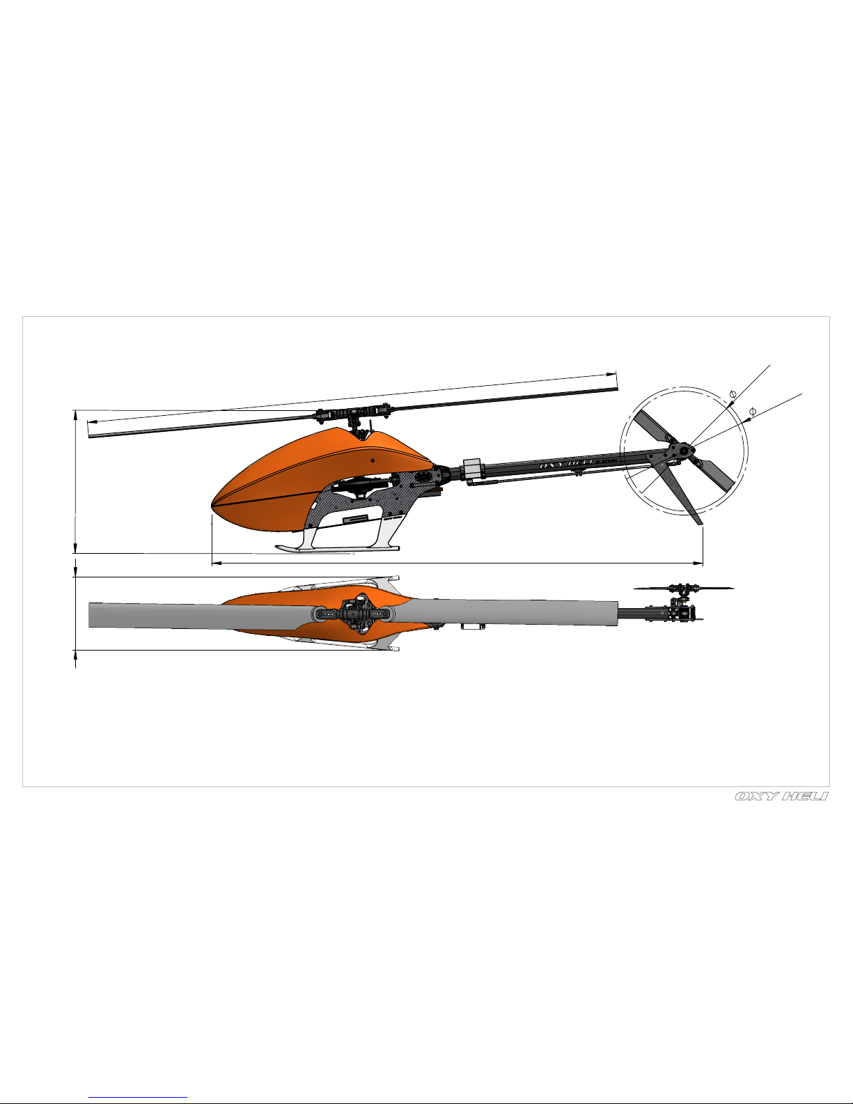
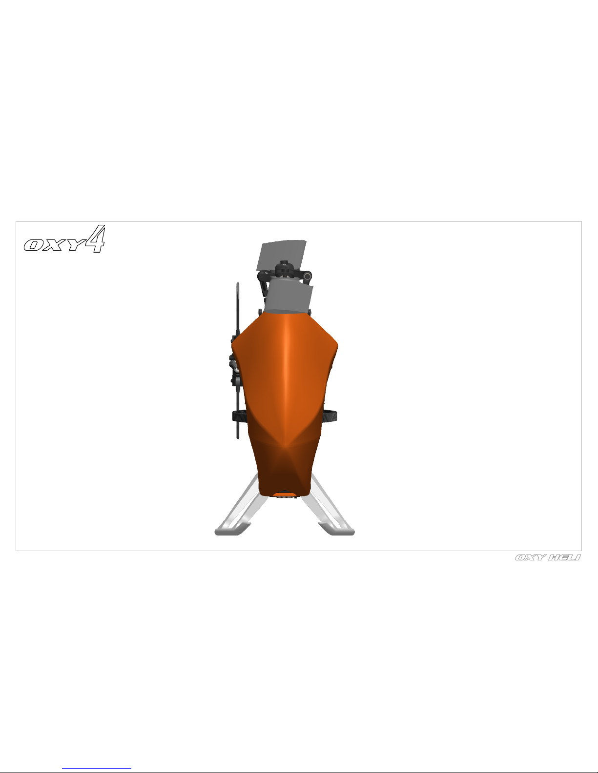
740mm
200mm
685mm
166.5mm
178.50mm
105mm
Chapter 1, Specifications
page 2
- Visit the Oxy Heli web site www.oxyheli.com to download the latest version of the manual.
- Inside Box 3 you will find your serial number card. Please take a moment to visit the Oxy Heli web site and follow the instructions to register your helicopter and serial number.
- It is important you take few minutes to register your helicopter and serial number with us. This is the only way to be in contact with us to receive news, promotional information and technical tips.
- We will also choose five serial numbers each year that will win a discount coupon worth 200USD each to spend at the Oxy Heli or Lynx Heli web sites.
- Thank you for your purchase, and we wish you the best enjoyment with your new Oxy 4 Helicopter.
VERY IMPORTANT NOTE:
-Standard main rotor diameter
-Standard main blade length
-Main Grip Clamping
-Standard tail rotor diameter
-Standard tail blade length
-Tail Blade Clamping
-Weight
-Maximum motor size
-Maximum battery size
-Recommend battery
: 740mm (with 325mm blades).
: 325mm
: M3 / 6 mm root.
: 178.5 mm.
: 62-68 mm.
: M2 / 3.5 mm root.
: 800g (ready to fly excluding batteries)
: diameter 33mm.
: length 105mm, height 35mm, width 43mm, 260 weight gr
: max size.....

IMPORTANT NOTE:
This model helicopter has been designed and produced to be a high performance 3D machine. With its simple design and low parts count, pilots of all skill levels will appreciate its easy repairability. This is not a toy.
Please take care assembling the model, and take care and responsibility when you fly it. We take no responsibility for any damage or injuries, either direct or consequential, from the use of this product. If you are not
experienced in the assembly and flying of a high performance model helicopter we recommend you seek the assistance of an experienced pilot. Above all, fly safely and we hope you enjoy this model.
SAFETY GUIDELINES:
Only fly this model in areas designated for the use of model aircraft. Ensure you obtain indemnity insurance, normally available
through your National model aircraft association. Remain at least 6 meters (20 feet) from the model at all times. Never allow
spectators or animals any closer than 30 meters (100 feet) from the model.
NOTES FOR ASSEMBLY:
Please read this instruction manual fully before beginning assembly of this model helicopter. Be sure to use quality tools during the assembly process, and remember not to overtighten small fasteners. Note the following
symbols which are used in this manual. Use thread lock sparingly where indicated. If you are unsure about an assembly step, please seek the advice of an experienced pilot. Warranty on any parts is only applicable
prior to assembly of the part on the model.
NONE OF THE PRE ASSEMBLED PARTS HAVE THREAD LOCK ON THE SCREWS. IS IMPORTANT TO READ AND FOLLOW THE ASSEMBLY NOTES IN EACH STEP.
INCORRECT ASSEMBLY OR NOT USING THREAD LOCK WILL CAUSE A CRASH OR INJURY.
Important note
Use CA Glue
Use Loctite 243 Medium Strength
Use Loctite 648 Bonding
Use Silicone Grease
page 3
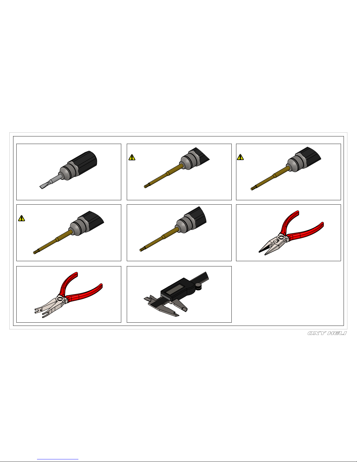
TOOLS REQUIRED
Chapter 3, Required Tools for assembly
Small Tip - Flat Screw Driver
1.5mm Hex Screw Driver
(High quality)
One Tools Required
1.3mm Hex Screw Driver
(High quality)
One Tools Required
2mm Hex Screw Driver
(High quality)
2.5mm Hex Screw Driver
(High quality)
Needle Nose Pliers
Uniball Pliers
Caliper
page 4
Two Tools Required
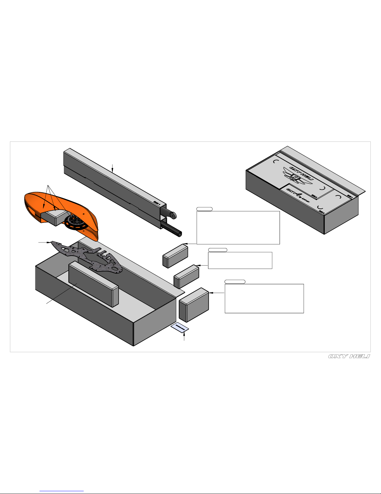
Chapter 4, What's inside the box
ASSEMBLY PARTS FINDER HELP NOTE:
In each assembly step you will see a parts finder note. Follow
this information to find the necessary parts inside the Oxy 4 box.
page 5
Canopy, Main Gear
& Accessories Bag
Tail Boom
Tail Push Rod
Main Blade
Main Frame
Landing Gear
Box 3/ Bag 1 Vertical Fin & Tail Case Assembly
Box 3/ Bag 2 Tail Rotor Assembly
Box 3/ Bag 3 Tail Shaft Set
Box 3/ Bag 4 Tail Pitch Slider Assembly
Box 3/ Bag 5 Tail Belt Crank & Tail Belt Tensioner
Box 3/ Bag 6 Tail Belt Set
Box 3/ Bag 7 Tail Servo Mount Set
Box 3/ Bag 8 Tail Blade Set
Box 3/ Bag 16 Main Shaft Set
Box 3/ Bag 17 Main Rotor Assembly
Box 3/ Bag 18 Swash Plate Assembly
Box 3/ Bag 19 Servo Arm Set
Box 3/ Bag 9 Boom Clamp Set
Box 3/ Bag 10 Upper Bearing Block Assembly
Box 3/ Bag 11 Middle Bearing Block Assembly
Box 3/ Bag 12 Lower Bearing Block Assembly
Box 3/ Bag 13 Canopy Mount Set
Box 3/ Bag 14 Motor Mount Set
Box 3/ Bag 15 Battery Tray Set
Tail Set
Head Set
Frame Set
Serial Number Card
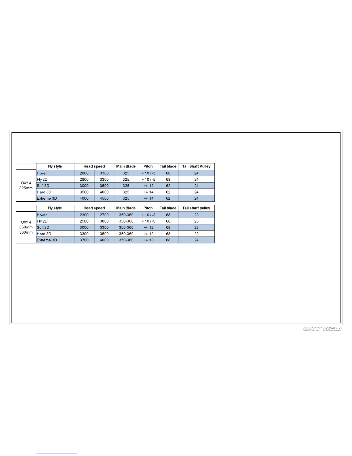
OXY 4 POWER SYSTEM AND HEAD SPEED SET-UP
In order to choose the best setup for your Oxy 4, and optimize performance, it is important to know some basic information:
1- Motor Kv – Min - Max - See your motor specification
2- Battery Pack – (3s or 6S)
3- Your target head speed
If you use a head speed calculator, use 150T for the main gear and one of the available pinions 14T – 15T – 16T – 17T -18T .
Head Speed Note: Although Oxy 4 can handle very high Head Speed, we suggest not to exceed 4500 RPM to maintain a good compromise btw performances and efficiency. Configuration examples Since the Oxy4 is a
high performance 3D RC
helicopter, we suggest using high quality power components including motor, battery and ESC. Remember the Oxy 2 is a 200 class heli – use light components to maximize flight time and performance. Here are some
suggestions:
-
Motor: Suggested 3SKV: 3500 to 4000 or 6SKV: 1500 to 1900, 2216 to 2620 caliber series (stator diameter – stator length).
-
Battery: 3S or 6S with capacity
3s to max 2250 (estimate) 6s to max 1800
(1800 max best suited for stretched Oxy 4)
45C discharge rate. Maximum size: length 110mm, height 34mm, width 43.5mm, weight 250g.
-
ESC: 50 to 60A – with BEC V or higher.
-
Cyclic servos: Standard Sub MICRO size servo speed: =>0.06 sec/60 at 6V.
-
Rudder servo: Standard MICRO size servo – speed =>0.06 sec/60 at 6V – a specific rudder servo is suggested for best tail authority.
-
FBL system: The Oxy 4 was designed around the U-Ikon / U-Brain and Neo V-Bar Systems. But many other smaller size FBL systems can be used, depending on your personal choice. Max inner Frame dimension 33mm.
-
Main blade: The Oxy 4 can fly with main blades from 320 to 360mm. Our testing was with Zeal 325mm and Zeal 360 Carbon main blade. The Oxy 4 main grips use M3 clamp screw and have a 6 mm root.
-
Tail blades: The Oxy 4 uses our own OEM tail blades, either 62 or 68mm (included with the kit). They use a M2 clamp screw and 3.5 root.
We offer 62 and 68mm tail blades to suit different head speeds. Use 68mm tail blades when your head speed is lower than 4500rpm and 68mm with higher head speeds.
Chapter 5: Pinion Selection & RPM
page 6
A
A
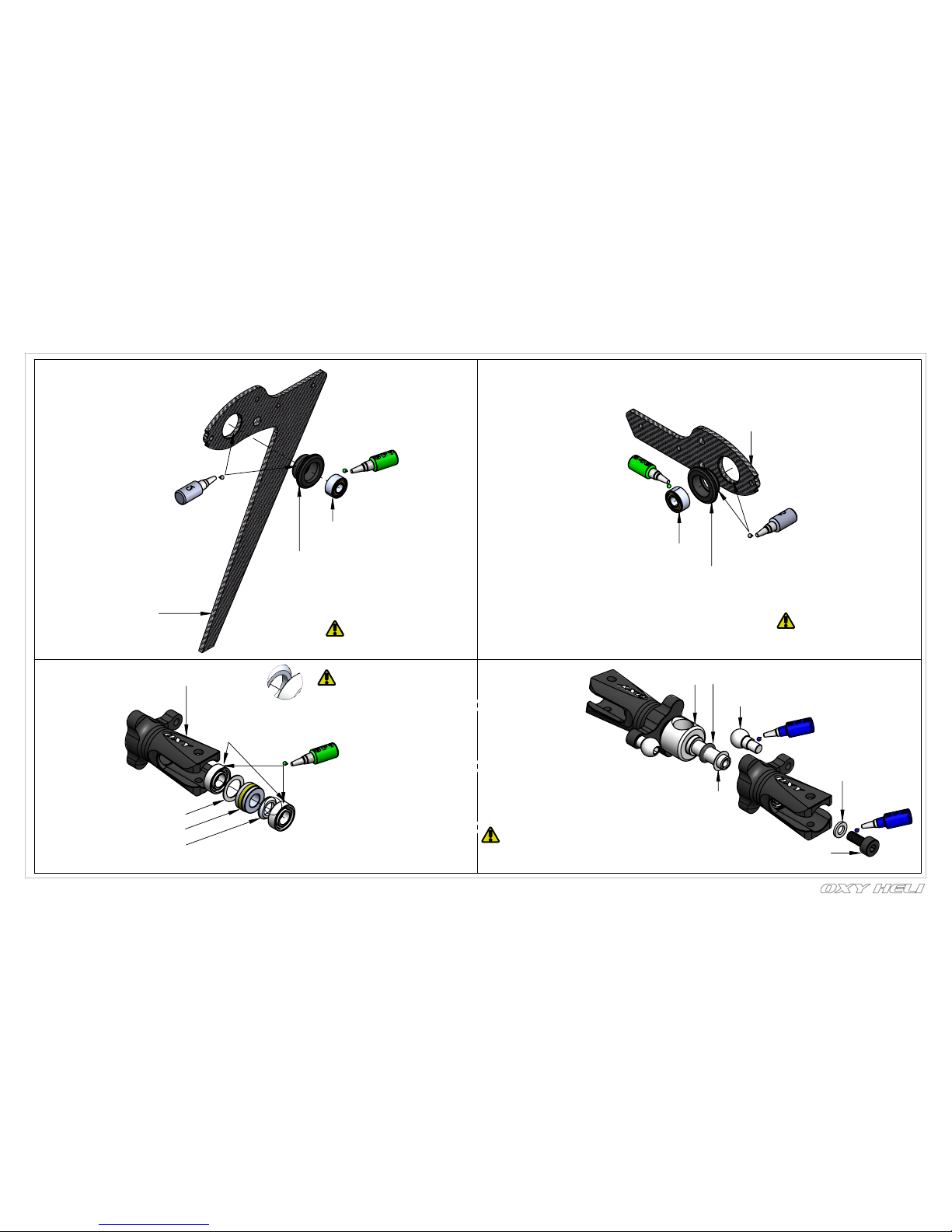
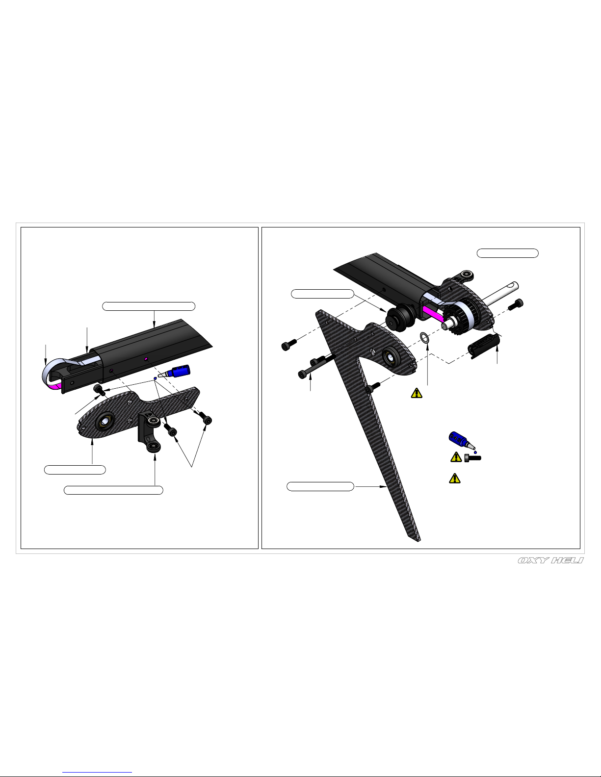
Chapter 6: Tail Assembly
page 7
Vertical Fin Assembly
(Box 3/Bag 1)
Important Note:
This part, for tuning reasons,
comes factory pre assembled,
it ready to us
OXY0353-OXY4Vertical Fin Block
OXY0354 -Vertical
Fin Bushing
MR684_ZZC Radial Bearing 4x9x4
Tail Case Assembly
(Box 3/Bag 1)
Important Note:
This part, for tuning reasons,
comes factory pre assembled,
it ready to us
MR684_ZZC Radial Bearing 4x9x4
OXY0358-OXY4 - Tail
Case Bearing Bushing
OXY0676-OXY4
CF Side Case
Tail Rotor Assembly
(Box 3/Bag 2)
MR63-X - 3X6X2
Radial Bearing
OXY0710 - OXY4
Tail Grip
Important Note:
This part, for tuning reasons,
comes factory pre assembled,
it ready to use
OXY0054 - 3X4X0.1 Shim
F3-6M-3x6x2.8 Thrust Bearing
OXY0723 - Tail Grip Spacer
Important Note:
This part comes pre assembled
WITHOUT thread lock. It MUST be
re-assembled with thread lock as shown.
OXY0344 OXY4-Tail Hub
O-Ring ID2 W1
OXY0054 3X4X0.1 Shim
OXY0050 - linkage
ball 4 X 3 M2
OXY0055 2X3.5X0.5 Washer
TCEM2X5 - M2X5
Hex Cap Screw
Chapter 6: Tail Assembly
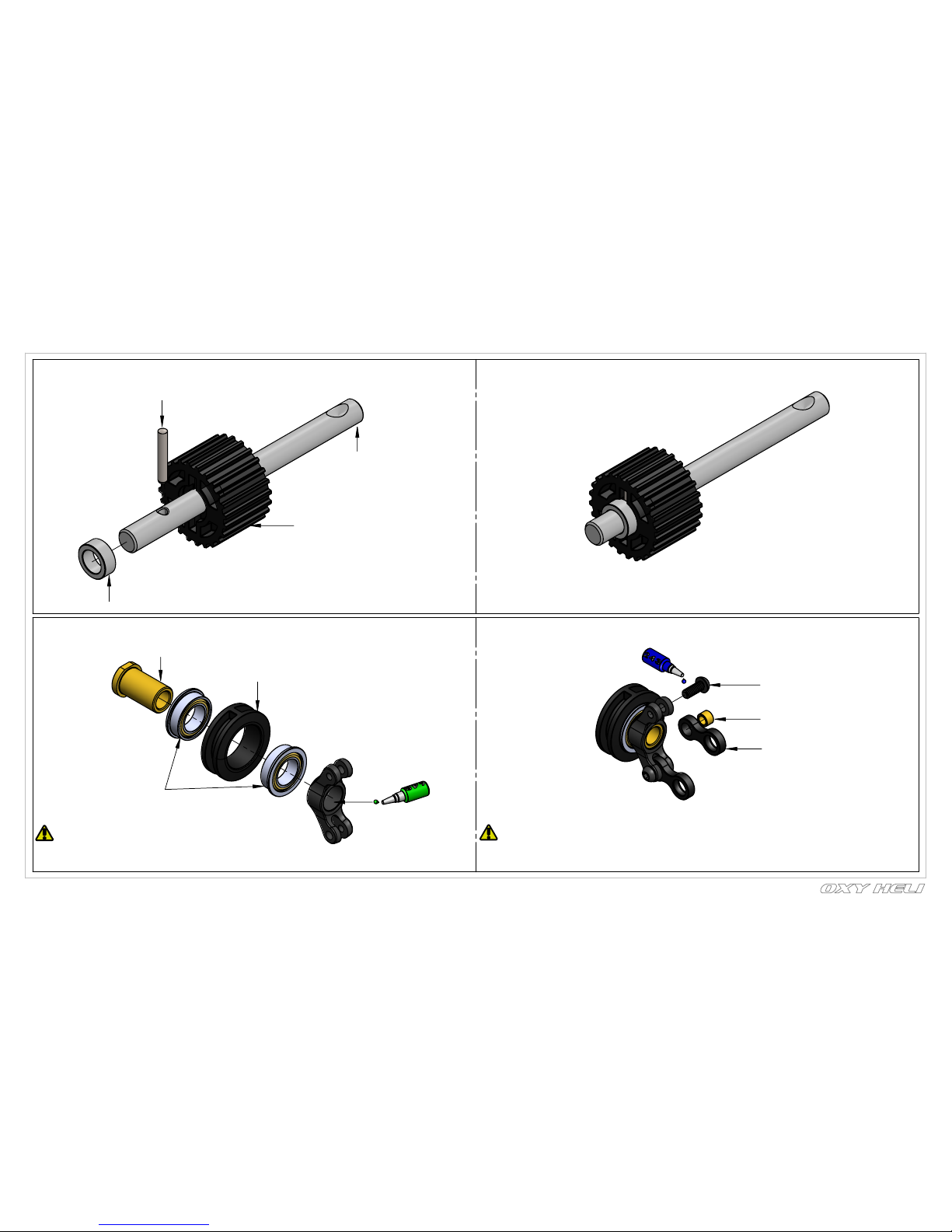
Tail Shaft Assembly
( Box 3 / Bag 3
)
OXY0733 - 1.5x9.5 Alloy
Steel Dowel Pin
OXY0743 - 4x6x2.5 Bushing
OXY0348 - Tail Shaft
OXY0726 - 24T Tail Pulley
Tail Pitch Slider Assembly
( Box 3 / Bag 4
)
Important Note:
This part, for tuning reasons,
comes factory pre assembled,
it ready to use.
OXY0345 - Tail Pitch
Slider Bushing
OXY0714 - Tail Pitch
Slider Ring
MF106-ZZ - 6X10X3
Flange Bearing
TBEM2X5 - M2X5 Button Screw
OXY0062 - 2X3X2 Bushing
OXY0064 - Link Control
page 8
Important note:
This part comes pre assembled
WITHOUT thread lock. It MUST be
re-assembled with thread lock as shown.

MR63_ZZC - 3X6X2.5 Radial Bearing
OXY0727 - 3x4x2.3 Bushing
OXY0674 - Tensioner Adapter
OXY0725-Pulley Guide Belt
Tail Belt Tensioner Assembly
( Box 3 / Bag 5 )
Tail Belt Crank Support Assembly
( Box 3 / Bag 5 )
Tail Belt Crank Assembly
( Box 3 / Bag 5 )
Important Note:
This part, for tuning reasons,
comes factory pre assembled,
it ready to use
2xMF682ZZ-2X5X2.3
Flange Bearing
OXY0673-Bell Crank Support
Chapter 6: Tail Assembly
Important Note:
This part, for tuning reasons,
comes factory pre assembled,
it ready to use
Important Note:
This part, for tuning reasons,
comes factory pre assembled,
it ready to use
page 9
OXY0724-Tail Bell Crank
OXY0057-Tail Pin Screw
0.50
Chapter 6: Tail Assembly
OXY0357-STD Carbon Rod
OXY0666-OXY4 SST Threaded Rod M2X10
OXY0716-linkage Ball M2 thread
Note: to install this
pin screw rotate
counter clock wire
OXY0620-Guide
Push Rod
2 x OXY0539Pin Screw
Note Pin Screw Thread:
Oxy designed the Pin Screw with
a counter clockwise thread. This
will help on the final locking
operation. Be careful to follow our
instructions to get a perfect assembly
Note: Install the Pin Screw
and leavea gap as shown.
Step 2:
Step 1:
page 10
Important Note:
This part, for tuning reasons,
comes factory pre assembly,
it ready to use
Push the part inside the
boom sockets as shown
Step 3:
Step 4: Slide the parts as shown
In order to lock the tail push rod
support, use a Flat Screw Driver
and turn clockwise. Do not
over tighten.
Step 5:
Chapter 6: Tail Assembly
OXY0303 - Tail Boom Assembly
OXY0343 - Tail Case Insert
B516MXL Timing Belt
( Box3 / Bag 6 )
TCEM2X5 - M2X5
Hex Cap Screw
2 x TCEM2X6 - M2X6
Hex Cap Screw
Tail Case Assembly
Tail Bell Crank Suppport Assembly
page 11
Tail Shaft Assembly
Tensioner Assembly
4 x TCEM2X6 - M2X6
Hex Cap Screw
Fine Adjust Shims Note :
In order to give fine adjustment options,
in the Extra Hardware Bag you will find
extra shims 4X6X0.1.
Start assembly WITHOUT any
shims. If Tail Shaft has sideways play
more than 0.2mm,
add shims as required, to one side, as shown.
PRO TIPS: For best Tail performances little
side play is recommended.
Note: all screws in this step
need add loctite during assembly.
Vertilcal Fin Assembly
before install any shim
read carefully fine
adjustment shims note.
TCEM2X22 - M2X22
Hex Cap Screw
OXY0648 - Tail Case Rod
Chapter 6: Tail Assembly
SCM3x3Set Screw M3x3
2 x TBEM2X6 - M2X6
Button Screw
Tail Bell Crank Assembly
2 x M2X6 Button Screw
Note: Line up the
holes, so the set
screw seats correctly
into tail shaft lock hole.
page 12
OXY0717 - PL
Tail Servo Support
(Box 3 / Bag 7 )
Note: don't install any screw
TAIL BELT ASSEMBLY AND DIRECTION CHEK:
In order to check correct belt install,
move belt position A CW and
the position B must rotate CW.
Before go forward on Tail Assembly check carefully
if Belt is installed per need.
Belt MUST move without any friction.
A
B
Step 5-1:
Tail belt is showed straight coming out,
form tail boom. Be careful to
check the belt if not twisted inside the boom.
Use a flashlight to check inside the boom, for better vision.
Rotate the belt 90 degrees CCW as shown.
90 CCW Rotation.
page 13
Chapter 6: Tail Assembly
Chapter 6: Tail Assembly
Step 5-2:
Hold carefully Tail Belt as showed and insert
Front Boom Insert.A
OXY0450-Front
Boom Insert
(Box 3/Bag )
Press in this insert parts into
Tail Boom to help Tail Belt
doesn't twist in the next
installation step
Step 5-3:
Final Tail Belt Direction Check:
Pull Tail Belt (as shown) and check the tail hub rotates
in the direction shown. If the Tail Rotor rotates
in the wrong direction, go back to the previous
instructions and double check your assembly.
Pull Tail Belt here
page 14
page 15
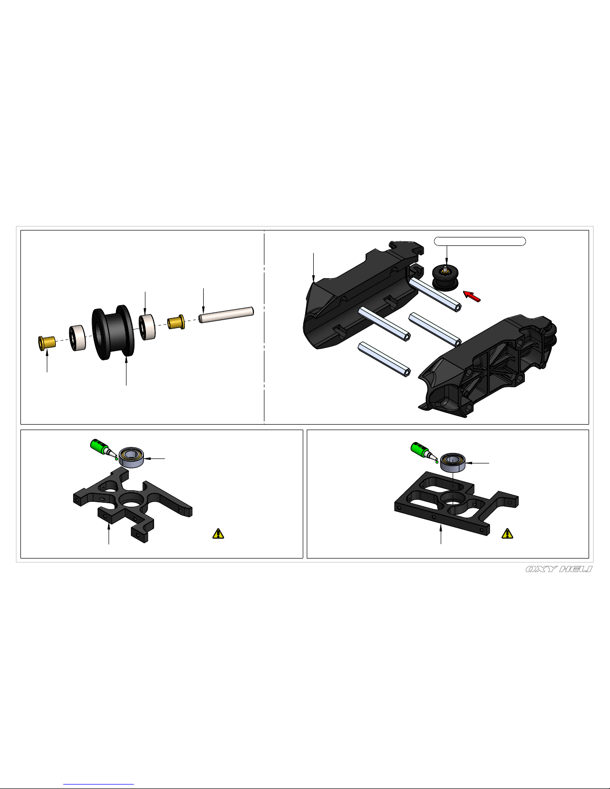
Chapter 7: Main Frame Assembly
Install the Pins into the Pulley
Guides and press completely into
the Tail Boom Clamp Socket Lips.
OXY0660 - Hexagon Rod
2 x Pulley Guide Belt Assembly
OXY0683 - Boom Clamp
OXY0668-Bell Crank Bushing
OXY0725-Pulley Guide Belt
OXY0023-2X13.5 PIN
SMR682Z-ZZ -
2.5X6X2.6 Radial Bearing
OXY0352 - Upper Bearing Block
RM126-ZZ - 6x12x4
Radial Bearing
OXY0352 - Upper Bearing Block
RM126-ZZ - 6x12x4
Radial Bearing
Boom Clamp Assembly
( Box 3/ Bag 9 )
Upper Bearing Block Assembly
( Box 3/ Bag 10 )
Middle Bearing Block Assembly
( Box 3/ Bag 11 )
Important Note:
This part, for tuning reasons,
comes factory assembled,
it is ready to use.
Important Note:
This part, for tuning reasons,
comes factory assembled,
it is ready to use.

17.50
33
16
Chapter 7: Main Frame Assembly
Left
Righ
OXY0425 Break Away Canopy
OXY0082 - Canopy Mount
TBES2X6 - M2X6 Self
Tapping Screw
OXY0331- Lower Bearing Block
RM126-ZZ 6x12x4 Radial Bearing
SCM3x3 Set Screw M3x3
Pinion (15T-3.5mm Motor Shaft included )
TCEM3X8 M3X8 Hex Cap Screw
OXY0336 - Motor Mount
page 16
Lower Bearing Block Assembly
( Box 3/ Bag 12 )
Break Away Canopy Assembly
( Box 3/ Bag 13 )
Motor Assembly
( Box 3/ Bag 14 )
Important Note:
This part, for tuning reasons,
comes factory assembled,
it is ready to use.
This hole is in the
nose of helicopter

Chapter 7: Main Frame Assembly
page 17
7 x M2x6 Hex Cap Screw
Note: Don't fully tighten yet.
Wait future neccessary
assembly step.
OXY0661 - Main Frame
Upper Bearing
Block Assembly
Middle Bearing
Block Assembly
3 x OXY0665 Hexagon 3mm
4 x all screws in this step
Note: Don't fully tighten yet.
Wait future neccessary
assembly step.
Lower Bearing
Block Assembly
FHSM2X4 M2x4 Flat Head Screw
OXY0711 Anti rotation Guide
4 x TCEM2X5 M2X5 Hex Cap Screw
7 x TCEM2X6 M2X6 Hex Cap Screw
Battery Tray
( Box 3/ Bag 15 )

Chapter 7: Main Frame Assembly
page 18
Motor Assembly
Boom Clamp Assembly
OXY0663 - Boom Clamp
Stiffener CF
6 x TCEM2.5X8 M2.5X8 Hex Cap Screw
OXY0332 M2.5 Washer
6 x M2.5x8 Hex Cap Screw
Note: Don't fully tighten yet.
TCEM2X6 M2X6 Hex Cap Screw
7 x M2x6 Hex Cap Screw
Note: Don't fully tighten yet.
See assembly alignment
Step page 23.

90°
90°
Chapter 7: Main Frame Assembly
4 x TCEM2x5 M2X6 Hex Cap Screw
page 19
6 x TCEM2.5x8 M2.5X8 Hex Cap Screw
All Screw in this step
Note: Don't fully tighten yet.
See assembly alignment
Step page 16.
Install main shaft with frame assembly
on a flat surface, push down on both frames
together and then fully tighten all M2 Hex Cap
Screws (x22) holding the bearing blocks.
Main Shaft
(
Box3 / Bag 16 )

Chapter 8: Main Gear Assembly
page 20
HF0812
One Way 8x12x12
OXY0655 One Way Hub
the Sleeve is free
rotate as arrow hown
MR148ZZ
8x14x3.5 Radial Bearing
5 x TBEM2X6 M2X6 Button Screw
OXY0657 Front Pulley Hub
OXY072188T Front Pulley
OXY0658 Front Flange Pulley
TBEM2X6 M2X6 Button Screw
OXY0720 - Main Gear
4 x TCEM2x6 M2X5 Hex Cap Screw
OXY0654 One Way Sleeve
2 x SCM3x3 Set Screw M3x3
Main Gear Assembly
(Box2 / Bag 1 )
Insert the Main Shaft
before you lock the Sleeve
2 Set Screw are seat onto the flat surface of
OXY0654 One Way Sleeve
Important Note:
This part, for tuning reasons,
comes factory assembled,
it is ready to use.
loctite 243
loctite 243
loctite 243
loctite 648

Chapter 9: Transmission Assembly
page 21
Tail Boom Assembly
Insert Tail
Assembly as shown
Before next assembly step check carefully
Tail Belt assembly position as shown.

3
2.50
3
Chapter 9: Transmission Assembly
OXY0656 One Way Screw
page 22
TCEM2X4 M2X4 Hex Cap Screw
OXY0656 One Way Screw
Main Gear Asssembly
In order to check the belt installation, we
recommend to follow two simple steps:
1- Check with light, look inside the boom
from the tail case and check the belt is
only twisted 90 degrees.
2- Rotate the main gear in the flight direction
(as shown) and check the tail hub rotates
in the direction shown. If the Tail Rotor rotates
in the wrong direction, go back to previous
instructions and double check your assembly.
Locitte 243

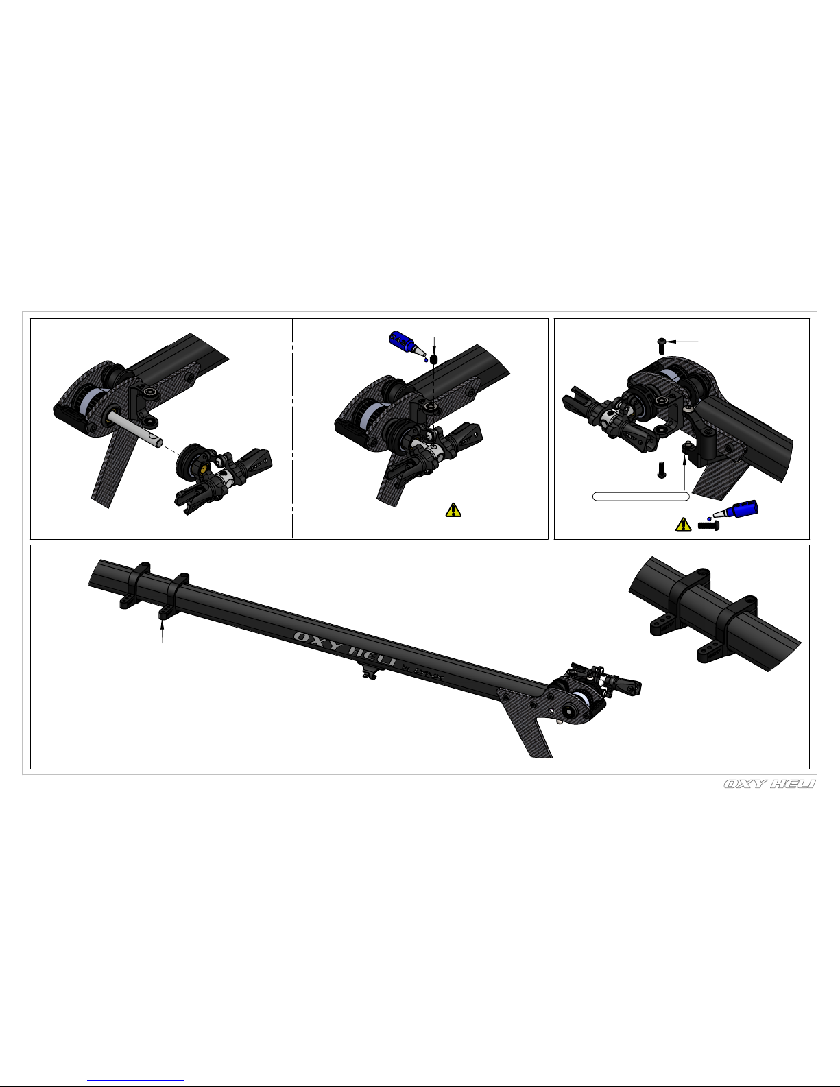
Chapter 10: Belt Tension & Adjustment
page 23
- Be sure the boom is assembled and installed correctly.
- Loosen the tail boom by loosening the eight M2.5x8 Hex Cap Screws.
- Adjust the Belt tension by pulling on the Tail Boom.
- Tighten the eight M2.5x8 Hex Cap Screws.
- The belt must have good tension. We suggest re-checking after a few
flights. We suggest to check belt tension often, before each flying session.
- If spool up get difficult, may Tail Belt is over tight,
recheck and eventually loose Belt tension little bit
- If the belt is often loose, you should check the lock system or belt integrity.
- Tests show that a hard 3D pilot can perform over 400 flights before the belt
will fail. We recommend replacing the Tail Belt after 300 flights, even if it
does not show wear, to avoid it breaking unexpectedly in flight.
- After a crash, spend some time checking Belt integrity and replace if any
teeth are missing.
4 x TCEM2.5x8 M2.5x8 Hex Cap Screw
2 x SCM4x3 Set Screw M4x3
OXY0451-Main
Shaft Collar
Push down Main
Shaft Collar
Pull up Main Shaft
Use a Screw Driver to check
Belt Tension (suggested max
deflection is 1mm)
- Note: We recommend a tight
Belt tension.
- If spool up get difficult, may Tail Belt
is over tight, recheck and eventually
loose Belt tension little bit
- Check the Belt tension again
after the first 2 flights.
- With a new Tail Belt, when the
head is rotated slowly, it is normal
to hear a tooth sound as the belt
engages with the Main Pulley. This
sound is normal and will disappear
after a few flights and the necessary
"break-in".
Loctite 243

Ref 35mm
A
loctite 468
loctite 468
4.2mm
4mm
Chapter 11: Main Rotor Assembly
page 24
2 x MR104_ZZC 4X10X4 Radial Bearing
F4-10G - 4X10X4
Thrust Bearing
Shim 4x6x0.1
Important Note:
This part, for tuning reasons,
comes factory pre assembled
with grease and loctite. It is
ready to use.
add silicone grease
OXY0666 Threaded Rod M2X10
OXY0716 PL linkage Ball
OXY0734-DFC Arm
OXY0012 DFC Arm Spacer
2 x MR52-W22X5X2 Radial Bearing
Fine Adjust Shims:
In order to give fine adjustment options,
the extra Hardware Bag contains extra
Shims 4x6x0.1. Start assembly
with one (each side)pre installed shim.
If the Main Grips have
sideway play, add shims as required.
Each Grips must have the same number
of shims. If you add one shim on the left
side, you need to also add one shim on
the right side
Important Note:
This part comes pre assembled
WITHOUT thread lock. Follow
the instruction for final assembly.
Step Faced to Main Grip
TCEM2.5X6M2.5X6 Hex Cap Screw
OXY0332-M2.5 Washer
OXY0324 - Center Hub
OXY0339-Spindle Shaft
OR6x1.5-Oring
ID6x1.5 Shore 80-90
OXY0325Damperner Bushing
OXY0680-Damperner Spacer
OXY0361-Shim 4x6x0.1
Main Rotor Assembly
( Box 3/ Bag 17 )
loctite 243

Important Note:
This part comes pre assembled
WITHOUT thread lock. Follow
the instruction for final assembly
Chapter 11: Main Rotor Assembly
OXY0757Main Grip Bushing
TCEM2X18M2X18 Hex Cap Screw
OXY00552X3.5X0.5 Washer
DFC Arm
Once you finish assembly, ensure the DFC
Arms can rotate without friction. If the DFC
Arms are assembled correctly, rotation
should be smooth and without friction. In
case of any friction, recheck each
component and re-assembly as necessary.
Lower and Upper
Swash Plate
OXY0020-M1.2x2
Special Screw
Center Ball
Important Note:
this part, for tuning reasions,
comes factory pre assembled,
it ready to use.
OXY0018-2x
11.5 Anti Rotation Pin
OXY0019 Swash Plate Ball
OXY0043 Linkage Ball
Important Note:
This part comes pre assembled WITHOUT
thread lock. Follow the instruction for final
assembly.
Swivel Ball Note:
The Swivel Ball is pre-assembled with a
precise fitting. When new, the Swash Plate
center ball will have a little friction. After a
few flights and “break-in” it will come smooth,
keeping the best precision without play.
page 25
Swash Plate Assembly
( Box 3/ Bag 18 )
loctite 243
loctite 243
loctite 243

Chapter 11: Main Rotor Assembly
page 26
Head Assembly
M2.5x12 Hex Cap Screw
M2.5 Self Lock Nut
2 x M2.5x8 Button Screw
loctite 243

7.50
10
10.25mm
Max 15mm
Chapter 12: Servo & Servo Rod Prepareration
page 27
-
You should now do some initial setup of your FBL unit and servos.
- We recommend you select a new model in your transmitter, and reset your FBL unit and start with a clean setup in it as well.
- After binding your transmitter to the receiver system used with the FBL unit, work your way through the FBL setup instructions to the point
you plug in your servos.
- Now set your collective stick in the middle position, and position the servo arms as close to the correct positions you can on each servo
see the following pages for arm orientations on the various servos.
- Next confirm the servos work in the correct direction, then return the collective stick to the center position.
- Now use your FBL unit to trim the servos so the arms are exactly horizontal (see pictures below).
- This procedure varies between units. Carefully label the position of the servos, then proceed with the installation of the servos as shown.
It is really important the servo rods screw onto
the linkages the same amount. The Plastic
ball links have a Lynx logo to give you
information about turn adjustment, but have
a symmetrical ball socket shape and can be
installed in either direction to achieve the
best fine tuning.
Linkage Ball Position
After Cut
OXY0085 Servo Arm
( Box 3/ Bag 19 )
Front Cylic Servo
OXY0085 Servo Arm
OXY0092 -Linkage Ball
OXY0108 - M2 Hex Nut
Left Cylic Servo
Right Cylic Servo
OXY0716 PL linkage Bal
OXY0667 - Pitch Rod
Tail Servo
Optional Tail Servo
OXY0085 Servo Arm
OXY0092 -Linkage Ball
OXY0108 - M2 Hex Nut
OXY0108 - M2 Hex Nut
OXY0092 -Linkage Ball
OXY0085 Servo Arm
OXY0085 - Servo Arm
OXY0108 - M2 Hex Nut
OXY0092 -Linkage Ball
Mini Servo
Mini tail
servo spacer
OXY0736 - CF Tail
Servo Stiffener
4 x M2x8 Self
Tapping Screw
loctite 243
loctite 243
loctite 243
loctite 243
CA Glue

Chapter 13: ESC Installation
page 28
Double - side Tape
( Accessories Bag )
ESC
use your choice of
connector rated
Be carefully Motor wire
and ESC will not touch
Motor/Pinion.
Motor wires
2 x Cable Tie
Battery wires
Use 3 x cable ties, to secure the Throttle ESC wire to the main frame. Use the Frame
built-in socket for best holding. In this Step connect the Motor and ESC Wires but don't
secure yet. Wait till the final motor rotation check, once the FBL system is set up.
NOTE: To reverse Motor rotation direction , just switch 2 of the 3 wires.

Chapter 14: Flybarless Installation
page 29
Flybarless Unit
Position 1
Double - Side Tape
The FBL system can be
installed at the bottom or
top of the boom clamp.
We suggest to use the
bottom for easy wiring
and servo removal.
For extra FBL support we
suggest to add Electronic
Hook and Loop as shown.
Flybarless Unit
Position 2

2 x TCEM2x6 M2x6 HexCap Screw
page 30
2 x TCEM2x5 M2x5 HexCap Screw
M2 Washer
Servo Layout
3 x Servo Rod Assembly
Chapter 15: Cylic Servo Installation
loctite 243
loctite 243

Chapter 16: Tail Servo Installation
page 31
Optional Tail Servo Installation
2 x TBES2X6 - M2x6
Self Tapping Screw
2 x M2 Washer
2 x TBES2X8 - M2x8
Self Tapping Screw
OXY0717 - PL
Tail Servo Support
Tail Push Rod Asembly
Micro Servo Assembly
Mini Servo Assembly
2 x TBES2X8 - M2x8
Self Tapping Screw
4 x TBES2X8 - M2x8
Self Tapping Screw

90°
3.50°
Chapter 16: Tail Servo Installation
page 32
Nose Right
Nose Left
Arm position with
centered Rudder stick.
Leveler
( Accessories Bag )
With Rudder Stick centered
and the Tail Servo Arm in the
center position, adjust the
Tail Push Rod length until the
Tail Bell Crank and Tail Case
Plate are parallel as shown.
The Oxy 4 Tail System has
approximately 3.5 of counter
torque with the Tail Bell Crank
set per instructions.

Chapter 17: Landing Gear & Battery Installtion
page 33
Landing Gear & Battery Installtion
Battery Straps
( Accessories Bag )
Landing Gear Skid
Main Blades Installation
Tail Blades Installation
Satellite
EX
6 x M2.5x10 Self
Tapping Screw
don't over tighten
M3x18 Hex Cap Screw
325mm Main Blade
M3 Self Lock Nut
Tail Blade
( Box 3 / Bag 8 )
OXY0078 - M2x10
Button Screw

Before Fly:
Now complete the setup of your FBL system. In the Accessories Bag you will find an Oxy 4 Swash Plate Leveler.
This Tool is designed to fit under the Swash Plate without disassembly any parts. This simple tool will both level the swash and give
the Zero Pitch Position.
Starting gyro gain: The Oxy 4 was designed around famous FBL Systems (IKON / Brain / mini V-Bar), and we suggest you start with
the following standard set up and adjust after test flying.
Cyclic Set Up:
Use suggested settings for 450 Helicopters and adjust after test flights.
See our table on page 15 for RPM and Pitch Settings. Cyclic Max pitch should be +/- 10.5 deg.
Tail Set Up:
Use the suggested settings for 450 Helicopters BUT start with a lower Tail Gain
IKON / Brain = 20%
Mini V-Bar = 250 Heli suggested gain.
Chapter 19: Adjustment Servo With Leveler
page 34
Lift up swash plate
as shown to have
space for inserting Leveler.
Rotate Leveler as shown
Lower Swash Plate down
untill Swash Plate
touch Leveler as shown.

Chapter 20: Canopy Installation
page 35
Canopy

4.50mm
Chapter 21: Addendum - FBL Head System
page 36
FBL Head System not Included in the kit
2.5X4.2X0.35 Spacer
OXY0080 -Uniball
Radius Arm
2 x SMR628_ZZC - 2.5X6X2.6
Radial Bearing
OXY0089 Pin 1.5X9.5
OXY0750-M2x15 Threaded Rod
OXY0716 - linkage Ball
OXY0433 - Link Ball
OXY0434 - Main
Grip Bushing
OXY0055 -
2.6X4.2X0.35 Washer
TBEM2.5x14 - M2.5x14
Button Screw
Self Lock Nut M2.5
TCEM2.5x12 - M2.5x12
Hex Cap Screw

1
2
3
4
5
6
7
8
9
10
11
12
13
14
15
16
17
18
19
20
21
22
23
29
24
24
26
27
28
30
31
Chapter 22: Exploded View, Main Rotor
page 37

1
2
3
4
5
6
7
8
9
11
10
12
13
14
15
18
16
17
20
19
Chapter 22: Exploded View, Main Frame
page 38

1
2
3
4
5
6
7
8
9
21
20
10
14
18
16
15
17
19
22
11
12
Chapter 22: Exploded View, Main Frame
page 39

2
6
5
3
4
7
8
9
10
11
12
13
14
15
16
17
18
19
20
21
22
23
24
25
26
27
28
29
30
31
32
10
34
35
36
37
38
39
40
41
42
43
44
454647
48
Chapter 22: Exploded View, Main Frame
page 40

Chapter 23: Spare Parts - Head Parts
page 41
OSP - 1002
OXY4 - Center Hub
1 x Center Hub
1 x M2.5x12 Hex Cap Screw
2 x M2X6 Hex Cap Screw
1 x M2.5 Self Lock Nu
OSP - 1003
OXY4 - Main Grip - Black, 2Pcs - Set
2 x Main Grip Assembly
2 x M3X18 Shouldered Hex Cap Screw
2 x M3 Self Lock Nut
OSP - 1004
OXY4 - Main Grip Service Bag
2 x 4X10X4 Thrust Bearing
4 x 4X10X4 RadialL Bearing
2 x Shim 4x6x0.1
OSP - 1005
OXY4 - Swashplate, Set
1 x Swash Plate, Set
OSP - 1006
OXY4 - Swashplate - Service Bag
1 x OXY4 Ball Holder
1 x OXY4 Center Ball
2 x M1.2x2 Special Screw
1 x 2x11.5 Anti Rotation Pin
3 x M2 Wash Plate Ball
4x Linkage Ball
OSP - 1007
OXY4 - DFC Arm, Service Bag
4 x OXY4-DFC Arm
OSP-1009
OXY4 - Carbon Steel Main Shaft
1 x OXY4-Main Shaft
1 x OXY4 Main Shaft Lock Ring
1 x M4x3 Flat-Tip Set Screw
1 x M2.5 Self Lock Nut
1 x M2.5x12 Hex Cap Screw
OSP - 1010
OXY4 - Carbon Steel Spindle Shaft
1 x OXY4-Spindle Shaft
2 x M2.5 Washer
2 x M2.5X6 Hex Cap Screw
OSP - 1011
OXY4 - Dampeners, 2 Set
4 x OXY4-Damperner Bushing
4 x Oring ID6x1.5
4 x OXY4-Damperner Spacer
4 x Shim 4x6x0.1
OSP - 1058
OXY4 - DFC set
2 x DFC Assembly
OSP - 1057
OXY4 - DFC Arm -Spacer Set, 4Pcs
4 x M2X18 Hex Cap Screw
4 x 2X3.5X0.5 Washer
4 x OXY4 - Main Grip Bushing - Black

Chapter 23: Spare Parts - Head Parts
page 42
OSP - 1013
OXY4 - Blade Holder
1 x OXY4 Blade Holder
OSP - 1048
Threaded Rod M2x20
10 x Threaded Rod M2X20
SP-OXY3-036
OXY3 - Servo Arm Set, 4 PC
4 x Servo Arm
4 x linkage Ball
4 x Hex Nut
OSP-1008
OXY4 - PL Linkage Ball, 10pcs
10 x Plastic Linkage Ball
OSP-1012
Threaded Rod M2x10
10 x M2x10 Threaded Rod
ZHM-NRG325C
1 x ZEAL Energy Carbon Fiber
Main Blades 325mm (Neon Orange)
10 x Hex Cap Screw M2x6
M2x6CS-10 Hex Cap Screw M2x6, 10 PCS
M2.5x6CS-10 Hex Cap Screw M2x6, 10 PCS
10 x Hex Cap Screw M2.5x6
M2.5x12CS-10 Hex Cap Screw M2.5x12, 10 PCS
10 x Hex Cap Screw M2.5x12
M2.5-SLN-10 Self Lock Nut M2.5
10 x 10 Self Lock Nut M2.5
M3-SLN-10 Self Lock Nut M3
10 x 10 Self Lock Nut M3
SP-0072
OXY4 - Main Blade Shim Set
4 x 3x15x0.5 Shim
4 x 3x15x0.6 Shim
4 x 3x15x0.7 Shim
OSP-1059
OXY4-FBL-Head-System
1 Set FBL
OSP-1076-OXY4FBL-Antirotation-Arm, Service-Bag
OSP-1075
V2-FBL-Linkage-Ball,-Set
5 x FBL Still Linkage Ball
5 x FBL Bushing

Chapter 23: Spare Parts - Frame Parts
page 43
OSP - 1014
OXY4 - Main Frame
1 x OXY4 Main Frame
OSP - 1017
OXY4 - Tail Boom Clamp Mount, Set
2 x OXY4 Boom Clamp
4 x OXY4 H4x32mm M2.5
4 x OXY4 Boom Clamp Stiffener
8 x M2.5X8 Hex Cap Screw
OSP - 1018
OXY4 - Boom Mount Lock Rod
4 x OXY4 H4x32mm M2.5
8 x M2.5X8 Hex Cap Screw
OSP - 1019
OXY4 - Upper Main Shaft Bearing Block
1 x Upper Bearing Block
1 x 6x12x4 Radial Bearing
1 x M2x4 Flat Head Screw
3 x Washer M2
3 x M2X5 Hex Cap Screw
6 x M2X6 Hex Cap Screw
OSP - 1020
OXY4 - Middle Main Shaft Bearing Block
1 x Lower Bearing Block
1 x 6x12x4 Radial Bearing
3 x Washer M2
5 x M2X5 Hex Cap Screw
4 x M2X6 Hex Cap Screw
OSP - 1021
OXY4 - Lower Main Shaft Bearing Block
1 x Lower Bearing Block
1 x 6x12x4 Radial Bearing
4 x M2X5 Hex Cap Screw
OSP - 1022
OXY4 - Motor Mount
1 x OXY4-Motor Mount
4 x M2.5 Washer
8 x M2.5X8 Hex Cap Screw
OSP - 1023
OXY4 - Main Shaft Bearing Block
- Service Bag
3 x 6x12x4 Radial Bearing
OSP - 1024
OXY4 - Break Away Canopy Plate
2 x
Break Away Canopy Plate
OSP - 1025
OXY4 - Motor Mount Stiffener Plate
4 x OXY4 Motor Mount Stiffener
OSP - 1026
OXY4 - Carbon Anti Rotation Guide
1 x OXY4 - Anti rotation Guide

Chapter 23: Spare Parts - Frame Parts
page 45
OSP-1015-OXY4-CF-Bottom-Plate
1 x
CF-Bottom-Plate
6 x M2.5x10 Self Tapping Screw
OSP-1016-OXY4Plastic Landing Gear Skid,Set
1 Set landing Gear Skid
OSP - 1027
OXY4 - Belt Pulley Guide, Set
2 x Pulley Guide Belt Assembly
OSP - 1028
OXY4 - Main Gear, 2PC
2 x Injection Main Gear
OSP - 1029
OXY4 - One Way Hub Assembly
1 x Main Gear Hub Set
OSP - 1030
OXY4 - Front Pulley Assembly
1 x OXY4 - Front Pulley Hub
2 x Set Screw M3x3
OSP - 1031
OXY4 - Front Pulley Spare
1 x OXY4 88T Front Pulley
1 x OXY4- Front Flange Pulley
5 x M2X6 Button Screw
OSP - 1032
OXY4-One Way Sleeve
1 x OXY4 One Way Sleeve
1 x OXY4 One Way Screw
1 x M2X4 Hex Cap Screw
OSP - 1034
OXY4- Battery Tray
1 x OXY4 PL Battery Tray
3 x OX4 H3x32 M2
M2X6 Hex Cap Screw
OSP - 1052
OXY4 - Boom Clamp Stiffener, 4Pcs
4 x OXY4 Boom Clamp Stiffener CF
SP-OXY3-015
- OXY3 - Battery Oring , 4PC
OSP-1077
OXY3-OXY4 - Canopy Mount
4 x Canopy Mount
4 x Self Tapping Screw
4 x Battery Strap
OSP-1073
OXY4 - Sleeve Locking Screw
2 x Sleeve Locking Screw
2 x M2x4 Hex Cap Screw
M2.5x8CS-10 Hex Cap Screw M2.5x8, 10 PCS
10 x Hex Cap Screw M2.5x8, 10 PCS
M3x8CS-10 Hex Cap Screw M3x8, 10 PCS
10 x Hex Cap Screw M3x8, 10 PCS

Chapter 23: Spare Parts - Frame Parts
page 46
M2x6CS-10 Hex Cap Screw M2x6, 10 PCS
10 x Hex Cap Screw M2x6, 10 PCS
M2x5CS-10 Hex Cap Screw M2x5, 10 PCS
10 x Hex Cap Screw M2x5, 10 PCS
M2x4CS-10 Hex Cap Screw M2x4, 10 PCS
Hex Cap Screw M2x4, 10 PCS
M3x3SC-10 - Set Screw M3x3, 10 PCS
Set Screw M3x3, 10 PCS
M2x6BH-10 Button Hex Cap Screw M2x6, 10 PCS
Button Screw M2x6, 10 PCS
M2.5x8SBH-10
Self-TappingScrew M2.5x8, 10 PCS
10 x Self Tapping M2.5x8

Chapter 23: Spare Parts - Tail Parts
page 47
OSP - 1035
OXY4-Tail Shaft
1 x OXY4-Tail Shaft
1 x 1.5x9.5 Alloy Steel Dowel Pin
2 x Shim 4x6x0.1
OSP - 1036
OXY4 - Tail Case Hub
1 x OXY4 Tail Case Insert
4 x M2X6 Hex Cap Screw
OSP - 1037
OXY4 - Tail Case Cover
OXY4- Tail Case Rod
M2X6 Hex Cap Screw
OSP - 1038
OXY4 - Tail Case Bearing Block
Assembly
1 x Tail Case Assembly
2 x M2x6 Hex Cap Screw
OSP - 1039
OXY4 - Tail Pitch Slider
1 x Pitch Slider, Set
OSP - 1040
OXY4 - Tail Bell Crank
1 x Tail Bell Crank, Set
OSP - 1041
OXY4 - Bell Crank Support
OXY4 - Tail Bell Crank Support, Set
OSP - 1042
OXY4 - Tensioner Tail Belt
OXY4 - Tail Belt Tensioner, Set
OSP - 1043
OXY4 - Tail Grip
2 x Tail Grip Assembly
OSP - 1044
OXY4 - Tail Rotor Hub, Spare
1 x OXY4-Tail Hub
1 x Set Screw M3x3
2 x O-RING ID2 W1
2 x 3X4X0.1 Shim
2 x M2X5 Hex Cap Screw
2 x 2X3.5X0.5 Washer
OSP-1045
OXY4 - Vertical Fin
1 x Vertical Fin Set

Chapter 23: Spare Parts - Tail Parts
page 48
OSP-1046
OXY4 - 325mm Tail Push Rod Set
1 x Tail Push Rod, Set
OSP - 1047
OXY4 - 325mm Tail Boom
1 x Tail STD Boom
OSP-1049
OXY4 - Tail Servo Mount, Set
2 x Washer M2
2 x Self Tapping Screw M2x6
2 x Self Tapping Screw M2x8
2 x Tail Servo Mount
OSP-1050
OXY4 - Tail Blade 62mm - Black, 2Pcs
2 x Tail Blade 62mm
OSP-1051
OXY4 - Tail Blade 68mm - Black, 2Pcs
OSP - 1053
OXY4 - 23T Tail Pulley
OSP - 1054
OXY4 - 24T Tail Pulley
SP-OXY3-028 - OXY3
Tail Pitch Slider - Service Bag
2 x Bushing
2 x Link Control
2 x M2x5 Button Screw
SP-OXY3-025
OXY3 - Tail Rotor - Service Bag
2 x Steel Ball
2 x M2 Washer
2 x Shim 4.2x6x0.2
2 x Bearing Spacer
2 x Thrust Bearing 3x6x2.8
4 x Radial Bearing 3x6x2
2 x Button Screw M2x10
OSP-1071
OXY4 360mm Timing Belt Spare , 1Pcs
1 x 23T Tail Pulley
1 x Bushing
1 x Shim 4x6x0.1
1 x 1.5mm Pin
1 x 24T Tail Pulley
1 x Bushing
1 x Shim 4x6x0.1
1 x 1.5mm Pin
2 x Tail Blade 68mm
1 xTiming Belt B557MXL
1 x Front Boom Insert
OSP-1060
OXY4 325mm Timing Belt Spare
2 xTiming Belt B516MXL
2 x Front Boom Insert
OSP-1068
OXY4 - Stretch Kit 360 Combo
2 x Tail STD Boom
OSP-1069
OXY4 - 360 Tail Boom
OSP-1070
OXY4 - 360 - Tail Push Rod
OSP-1074
OXY4 - Mini Servo Adapter
1 x Mini Tail Servo Adapter
2 x Spacer
2 x M2x6 Self Tapping Screw
2 x M2x8 Self Tapping Screw
1 x 360mm Tail Boom

Chapter 23: Spare Parts - Tail Parts
page 49
M3x3SC-10
Set Screw M3x3, 10 PCS
10 x Set Screw M3x3
M2x8SBH-10
Self-Tapping Button Hex Screw
M2x8, 10 PCS
10 x Self-Tapping Button Hex Screw M2x8
M2x6SBH-10
Self-Tapping Button Hex Screw
M2x6, 10 PCS
10 x Self-Tapping Button Hex Screw M2x6
M2x5CS-10
Hex Cap Screw M2x5, 10 PCS
10 x Hex Cap Screw M2x5
M2x6BH-10
Button Hex Cap Screw M2x6, 10 PCS
10 x Button Screw M2x6
M2x5BH-10
Button Hex Cap Screw M2x5, 10 PCS
10 x Button Screw M2x5

Chapter 23: Spare Parts - Accessories Parts
page 50
OSP-1055
OXY4 - Leveler Tool
1 x Leveler Tool
OSP-1056
OXY4 - Vertical Fin Sticker
SP-OXY3-054
OXY3 - Battery Hook & Loop, 2 Set
SP-OXY3-055 - OXY3
Double Side Adhesive Tape, 2PC
SP-OXY3-057
OXY3 - Cable Ties Set
2 x OXY3 - Battery Hook & Loop, 2 Set 2 x Double Side Adhesive Tape
10 x Hex Cap Screw M3x18
M3x18CS-10
Hex Cap Screw M3x18, 10 PCS
M3x3SC-10
Set Screw M3x3, 10 PCS
10 x Set Screw M3x3
M2.5-SLN-10
Self Lock Nut M2.5
10 x Self Lock Nut M2.5
M2x8SBH-10
Self-Tapping Button Hex Screw
M2x8, 10 PCS
M2x6SBH-10
Self-Tapping Button Hex Screw
M2x6, 10 PCS
10 x Self-Tapping Button Hex Screw M2x6
M3-SLN-10
Self Lock Nut M3
10 x Self Lock Nut M3
M2x18CS-10
Hex Cap Screw M2x18, 10 PCS
10 x Hex Cap Screw M2x18
M2x6CS-10
Hex Cap Screw M2x6, 10 PCS
10 x Hex Cap Screw M2x6
M2x5CS-10
Hex Cap Screw M2x5, 10 PCS
10 x Hex Cap Screw M2x5
M2.5x12CS-10
Hex Cap Screw M2.5x12, 10 PCS
10 x Hex Cap Screw M2.5x12
10 x Self-Tapping Button Hex Screw M2x8

Chapter 23: Spare Parts - Accessories Parts
page 51
M2x6BH-10
Button Hex Cap Screw M2x6, 10 PCS
10 x Button Screw M2x6
M2x5BH-10
Button Hex Cap Screw M2x5, 10 PCS
10 x Button Screw M2x5
LX0362
3-4 mm Spindle Shaft Wrench
1 x 3 - 4 mm Spindle Shaft Wrench
LX1568
4mm Plastic Linkage Ball Reamer Too
1 x 4mm Plastic Linkage Ball Reamer Tool
M2x22SCS-10
Shoulder Hex Cap Screw M2x22, 10 PCS
10 x Shoulder Hex Cap Screw M2x22,
10 PCS
M4x3SC-10 - Set Screw M4x3, 10 PCS
10 x Set Screw M4x3, 10 PCS
OSP-1061
OXY4 STD Canopy
1 x Canopy
SP-0065
OXY4 - Helicoidal Pinion 14T
- 3.17mm Motor Shaft
SP-0066
OXY4 - Helicoidal Pinion 15T,
- 3.5mm Motor Shaft
SP-0067
OXY4 - Helicoidal Pinion 17T
- 3.5mm Motor Shaft
1x 14T -3.17mm Motor Shaft Pinion
1 x Set Screw M3x3
1x 15T -3.5mm Motor Shaft Pinion
1 x Set Screw M3x3
1x 17T -3.5mm Motor Shaft Pinion
1 x Set Screw M3x3
OSP-1086
OXY4 - Helicoidal Pinion 12T
- 3.17mm Motor Shaft
OSP-1087
OXY4 - Helicoidal Pinion 13T
- 3.5mm Motor Shaft
OSP-1088
OXY4 - Helicoidal Pinion 15T
- 3.17mm Motor Shaft
OSP-1089
OXY4 - Helicoidal Pinion 16T
- 3.5mm Motor Shaft
OSP-1090
OXY4 - Helicoidal Pinion 18T
- 3.5mm Motor Shaft
1x 12T -3.17mm Motor Shaft Pinion
1 x Set Screw M3x3
1x 13T -3.5 mm Motor Shaft Pinion
1 x Set Screw M3x3
1x 15T -3.17 mm Motor Shaft Pinion
1 x Set Screw M3x3
1x 16T -3.5 mm Motor Shaft Pinion
1 x Set Screw M3x3
1x 18T -3.5 mm Motor Shaft Pinion
1 x Set Screw M3x3

Chapter 23: Spare Parts - Accessories Parts
page 52
OSP-1091
OXY4 - Helicoidal Pinion 13T
- 3.17mm Motor Shaft
1x 13T -3.17 mm Motor Shaft Pinion
1 x Set Screw M3x3
OSP-1092
OXY4 - Helicoidal Pinion 14T
- 3.5mm Motor Shaft
1x 14T -3.5 mm Motor Shaft Pinion
1 x Set Screw M3x3
 Loading...