

Page 1
CABIN 400
Operating manual
Page 2

2
00010605 B
Contents
1 Introduction . . . . . . . . . . . . . . . . . . . . . . . . . . . . . . . . . . . . . . . . . . . . . . . . . . . . . . . 3
1.1 Preliminary note . . . . . . . . . . . . . . . . . . . . . . . . . . . . . . . . . . . . . . . . . . . . . . . . . . 3
1.2 User groups . . . . . . . . . . . . . . . . . . . . . . . . . . . . . . . . . . . . . . . . . . . . . . . . . . . . . 3
1.3 Standards . . . . . . . . . . . . . . . . . . . . . . . . . . . . . . . . . . . . . . . . . . . . . . . . . . . . . . . 4
1.4 Important notes . . . . . . . . . . . . . . . . . . . . . . . . . . . . . . . . . . . . . . . . . . . . . . . . . . 4
2 System construction and function . . . . . . . . . . . . . . . . . . . . . . . . . . . . . . . . . 5
2.1 Construction of the CABIN 400 ventilation and cooling system . . . . . . . . . . . . . 5
2.2 Function . . . . . . . . . . . . . . . . . . . . . . . . . . . . . . . . . . . . . . . . . . . . . . . . . . . . . . . . 6
3Application and use . . . . . . . . . . . . . . . . . . . . . . . . . . . . . . . . . . . . . . . . . . . . . . . . 8
3.1 Prior to commissioning . . . . . . . . . . . . . . . . . . . . . . . . . . . . . . . . . . . . . . . . . . . . . 8
3.2 Switching on the CABIN 400 . . . . . . . . . . . . . . . . . . . . . . . . . . . . . . . . . . . . . . . . 10
3.3 Adjusting ventilation settings . . . . . . . . . . . . . . . . . . . . . . . . . . . . . . . . . . . . . . . . . 11
3.4 Adjusting cooling settings . . . . . . . . . . . . . . . . . . . . . . . . . . . . . . . . . . . . . . . . . . . 11
3.5 Extra water feed for use in extremely dry and/or hot weather. . . . . . . . . . . . . . 12
3.6 Controlling the air stream . . . . . . . . . . . . . . . . . . . . . . . . . . . . . . . . . . . . . . . . . . . 12
3.7 Using the cooling function to the best effect . . . . . . . . . . . . . . . . . . . . . . . . . . . . 13
3.8 Required water purity and the use of additives . . . . . . . . . . . . . . . . . . . . . . . . . . 13
3.9 Filling the water reservoir . . . . . . . . . . . . . . . . . . . . . . . . . . . . . . . . . . . . . . . . . . . 14
3.10 Draining the water reservoir . . . . . . . . . . . . . . . . . . . . . . . . . . . . . . . . . . . . . . . . 14
3.11 Turning off the audible warning tone . . . . . . . . . . . . . . . . . . . . . . . . . . . . . . . . . . 16
3.12 When it freezes . . . . . . . . . . . . . . . . . . . . . . . . . . . . . . . . . . . . . . . . . . . . . . . . . . . 16
3.13 The meaning of the LED indicators . . . . . . . . . . . . . . . . . . . . . . . . . . . . . . . . . . . 17
4 Maintenance . . . . . . . . . . . . . . . . . . . . . . . . . . . . . . . . . . . . . . . . . . . . . . . . . . . . . . . 18
4.1 Cleaning the infeed vents (roof unit) . . . . . . . . . . . . . . . . . . . . . . . . . . . . . . . . . . 18
4.2 Replacing the air filters . . . . . . . . . . . . . . . . . . . . . . . . . . . . . . . . . . . . . . . . . . . . . 18
4.3 Cleaning the water pump filter . . . . . . . . . . . . . . . . . . . . . . . . . . . . . . . . . . . . . . . 21
5Storage mode . . . . . . . . . . . . . . . . . . . . . . . . . . . . . . . . . . . . . . . . . . . . . . . . . . . . . . 22
5.1 When . . . . . . . . . . . . . . . . . . . . . . . . . . . . . . . . . . . . . . . . . . . . . . . . . . . . . . . . . . 22
5.2 Function . . . . . . . . . . . . . . . . . . . . . . . . . . . . . . . . . . . . . . . . . . . . . . . . . . . . . . . . 22
6 Technical specifications . . . . . . . . . . . . . . . . . . . . . . . . . . . . . . . . . . . . . . . . . . . . 24
6.1 Technical details . . . . . . . . . . . . . . . . . . . . . . . . . . . . . . . . . . . . . . . . . . . . . . . . . . 24
6.2 Water quality . . . . . . . . . . . . . . . . . . . . . . . . . . . . . . . . . . . . . . . . . . . . . . . . . . . . 24
6.3 Functional principles of the OXYCELL when cooling . . . . . . . . . . . . . . . . . . . . . 25
7 Troubleshooting . . . . . . . . . . . . . . . . . . . . . . . . . . . . . . . . . . . . . . . . . . . . . . . . . . . . 26
8 Accessories, replacement parts and addresses . . . . . . . . . . . . . . . . . . . . 30
8.1 Replacement parts available from your dealer . . . . . . . . . . . . . . . . . . . . . . . . . . . 30
8.2 Dealer addresses . . . . . . . . . . . . . . . . . . . . . . . . . . . . . . . . . . . . . . . . . . . . . . . . . 30
Page 3

00010605 B 3
1 INTRODUCTION
1.1 Preliminary note
Your caravan / camper is equipped with an extremely innovative and user-friendly
OXYCOM ventilation and cooling system: the CABIN 400
We recommend you read this operating manual carefully in order to ensure proper
maintenance and correct use. Keep this manual in a safe place so that you can refer
to it at a later date.
Note
You can download the latest version of this manual from: www.oxycom.com
1.2 User groups
Owners/Users
To get the most out the CABIN 400, you need to have a thorough understanding of
how the unit functions. See "System construction and function" on page 5.
For daily use, see "Application and use" on page 8.
If you do not intend to use the CABIN 400 for a period of four weeks or more, the
system must be put into storage mode in order to prevent sediment and contaminant
build-up in the water reservoir and the OXYCELL (heat exchangers) in the roof unit.
For instructions, see: "Storage mode" on page 22.
The CABIN 400 is a robust system. Cleaning the inlet screen, the water reservoir and
the exhaust filter is the only maintenance required. (see "Maintenance" on page 18)
If the system is inadvertently switched on or if problems arise, see "Troubleshooting"
on page 26.
Installation
The CABIN 400 may not be installed by anyone other than your dealer. He has the best
knowledge of your vehicle and will adhere to all the relevant regulations and safety
standards when installing the unit.
Page 4
Introduction
4
00010605 B 4
Warni ng
All installation, maintenance and repair work must be carried out
as detailed in this operating manual. Failure to do so will
invalidate the warranty.
1.3 Standards
The CABIN 400 meets all relevant technical standards and certification. The unit has
been tested to EN 60335-1and EN 60335-2-40.
The conformity tests were performed by TüV- Rheinland (Germany) and DARE
Consultancy in Woerden (the Netherlands).
1.4 Important notes
The following notes are of great importance and must be taken into account when
installing or using the unit:
• The unit may only be connected to an electrical supply that is fused at a maximum
of 16 A.
• Repairs to the unit and the replacement of damaged wiring may only be performed
by authorised service engineers or personnel with similar qualifications.
• A type H05VV-F 3x0,75 mm2, or heavier, electrical supply cable must be used.
Page 5
00010605 B 5
2 SYSTEM CONSTRUCTION AND FUNCTION
2.1 Construction of the CABIN 400 ventilation and
cooling system
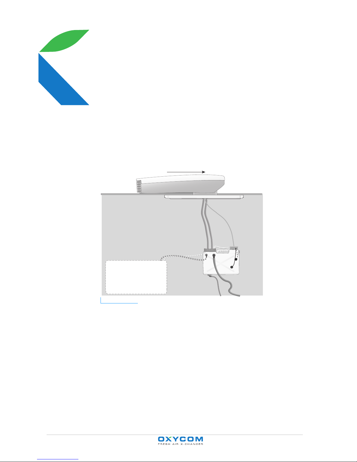
Figure 2.1 Schematic diagram showing the installed CABIN 400 system. The arrow indicates the
direction of vehicle movement.
• The roof unit (1): contains the OXYCELL (heat exchanger) and the fan.
• Inside the vehicle:
- The OXYZONE (2) allows adjustment of the horizontal and vertical air streams.
The operator panel is fitted to the OXYZONE.
- The water reservoir (3) for the water feed to and return from the roof unit
(OXYCELL), complete with screw-on cap (4) and connection box (5).
- Water feed hose (6), water return hose (7), reservoir drain hose (14), water
reservoir overflow (9).
- There are two pumps in the water reservoir. The feed pump delivers water to the
sprinkler in the OXYCELL (heat exchanger) in the roof unit. The return pump
returns excess water to the water reservoir.
1
2
3
4
5
67
8
10
13
11
9
12
14
Page 6

System construction and function
7
00010605 B 6
- Fresh water tank (12). As an optional extra, the CABIN 400's water reservoir can
be automatically replenished from the vehicle's fresh water system via a
solenoid valve. This is standard supply for campers and an optional extra for
caravans.
- The extra supply consists of a feed hose (13), a second float switch (11), a
suitably modified circuit board in connection box (5), a solenoid valve and all
the fasteners, etc, that are needed.
• Control system
- Low voltage control cable (8) between the OXYZONE and the float switch and
pump(s).
- Connection box (5), float switch, water pump and solenoid valve (optional). A
fuse for the 12 V control circuit is fitted in the connection box.
- Float switch in the water reservoir (10) signals when the water level is too low.
- Optional: 2. float switch (11), which switches off the automatic water feed from
the vehicle fresh water tank (12).
2.2 Function
To get the best out of your CABIN 400, it is important that you have a thorough
understanding of the unit's function. We therefore recommend that you carefully read
the following.
Ventilation and cooling
The CABIN 400 can:
• ventilate without cooling
• ventilate while simultaneously cooling
When ventilating, the air inside the caravan/camper is refreshed. When the cooling
function is activated the warm air inside the caravan is replaced by cooled air drawn
from the outside.
Cooling
The unit cools by withdrawing the heat energy required for the evaporation of the
water from the air stream. As the water evaporates, heat energy is withdrawn on the
secondary side of the OXYCELL (heat exchanger). This cools the primary side of the
OXYCELL. The warm air that is drawn in from outside is then cooled in the OXYCELL
before being blown into the camper / caravan.
For a detailed functional description, see "Functional principles of the OXYCELL when
cooling" on page 25.
The relationship between humidity and cooling capacity
The drier the outside air , the more moisture can be absorbed and the greater the
cooling effect.
The way the weather affects the performance (cooling capacity) of the CABIN 400 is
governed by the laws of physics regarding the ability of air to absorb moisture at
different temperatures. Cooling performance will be greater at higher temperatures
and low humidity than at low temperatures and higher humidity.
Page 7
System construction and function
7
00010605 B 7
In very damp weather, humidity will be extremely high and ambient air will be less
able to absorb extra moisture. For maximum CABIN 400 performance in these
weather conditions, the exhaust ducts of the OXYZONE should be opened fully and
the screen slide fully shut. The air stream will be clearly perceptible.
Water consumption
When the cooling mode is activated, water is pumped from the reservoir for a few
seconds at intervals of a number of minutes. The water is fed through the feed hose
to a sprinkler in the roof unit. The sprinkler moistens the heat exchanger. Any water
that is not immediately used by the heat exchanger returns to the reservoir through
the return hose. Evaporated water is exhausted to the outside via the roof, together
with the moist air (on the cooler side).
Depending on usage (cooling setting and the weather) the water reservoir will
gradually empty and will at some point need refilling.
Note
In extremely dry and/or warm weather (above 35oC), we recommend
increasing the frequency with which the heat exchanger is moistened.
See "Extra water feed for use in extremely dry and/or hot weather." on
page 12.
Note
As an option, the vehicle fresh water tank can be used to automatically
replenish the water reservoir. The parts required for this may only be
fitted by the dealer.
Advantages of the CABIN 400
• The construction and function of the CABIN 400 offer significant advantages in
comparison to typical air conditioning systems:
• Energy consumption is low: approx. 15% of the energy consumption of typical air
conditioning systems.
• Noise levels are low both inside and outside the caravan/camper. This keeps
nuisance to a minimum for both the user and the surrounding environment.
• The air is cooled very quickly; it is even possible to leave a window or door open
in the caravan/camper.
• The system is compact, light and does require much maintenance.
• The system is environmentally friendly:
- environmentally harmful cooling gases are not used;
- all the materials used in the manufacture of the CABIN 400 can be recycled.
Page 8

00010605 B 8
3 APPLICATION AND USE
3.1 Prior to commissioning
Water reservoir
Ensure there is enough water in the water reservoir. Use water of the same purity as
dr inking water . It is re comm ende d that an anti-algae additive is used. For instructions
about using additives see "Required water purity and the use of additives" on page 13.
For instructions on filling see "Filling the water reservoir" on page 14.
Note
The water reservoir has been carefully positioned by the installer. All
hoses have been installed carefully and without kinks. Do not tamper
with the installation in order to avoid catching or restricting any of the
hoses.
Power supply at the final destination
When the final destination is reached, the CABIN 400 receives its electrical supply via
the 230 Volt mains connection.
Power supply when travelling
When the CABIN 400 is used during the journey to the final destination, the electrical
supply is provided by the 12 Volt battery via a static converter. Even though the unit
consumes very little power, it should be noted that it can flatten the battery. As
standard, the Cabin 400 is fitted with a static converter with an automatic switch-in
function. Should the external 230 V supply be interrupted, the static converter will
automatically switch to battery power.
Page 9

Application and use
17
00010605 B 9
Note
When the vehicle is not in use, the static converter should be switched
of at the main isolator. Otherwise the unit will continue to draw a small
amount of power, which could flatten the batteries.
Ventilation and cooling
The operator panel on the OXYZONE is used to set the desired level of ventilation or
cooling (see "Adjusting ventilation settings" on page 11 and "Adjusting cooling
settings" on page 11). Air flow is regulated by adjusting the slides in the screen frame
and the exhaust vents of the OXYZONE.
Figure 3.1 A: OXYZONE base, B: OXYZONE extension (Option), C: end cover with adjustable
exhaust vents,
D: screen frame, E: operator panel
Page 10

Application and use
17
00010605 B 10
First commissioning of the CABIN 400
Your dealer has installed the CABIN 400 with the greatest possible care. However it is
recommended that you check that the water hoses running down to the water
reservoir are free of kinks. (see "Figure 3.2").
Figure 3.2 The water hose must be carefully positioned.
If the water hoses become kinked, water that has not evaporated will not return
properly to the water reservoir and could overflow out of the roof unit and drain off
over the roof. This will lead to higher water consumption.
3.2 Switching on the CABIN 400
Operator panel
Figure 3.3 CABIN 400 operator panel
Note
An audible tone will sound each time an adjustment is made, unless
this function has been switched off.
Switching on
When the CABIN 400 is switched off, none of the LEDs are lit or flash.
Press the On/Off switch . The CABIN 400 will automatically return to the settings
that had been selected before it was switched off, even if the cooling function was
L1
L2 L3
L4
Lp Lc
PC
V
P: CABIN 400 On/Off switch
V: Fan switch
C: Cooling On/Off switch
Lp: LED indicator light CABIN 400 On/Off
Lc: LED indicator light Cooling On/Off
L1: LED indicator light Ventilation/Cooling
1
L2: LED indicator light Ventilation/Cooling
2
L3: LED indicator light Ventilation/Cooling
3
Page 11

Application and use
17
00010605 B 11
activated. (If the CABIN 400 has been switched off for a long period, the cooling
initialisation program will start up first.)
Note
As soon as the CABIN 400 is switched on, the function that was in use
when the unit was switched off will be reactivated.
3.3 Adjusting ventilation settings
Press the fan switch . Each time the switch is pressed, the next ventilation setting
is activated:
Figure 3.4 Ventilation settings 1 to 4 are activated sequentially.
3.4 Adjusting cooling settings
The CABIN 400 must be switched on and the desired ventilation setting must be
activated.
1. Press the cooling switch .
Cooling starts. The fan will temporarily revert to level 1 so
that the OXYCELL can be properly moistened. The LEDs L1, L2,
L3, L4 on the operator panel will start to flash, when the
cooling function is first switched on. Water is pumped up from
the water reservoir to the sprinkler in the roof unit in order to
moisten the OXYCELL (heat exchanger). The moistening
process when cooling first starts lasts about 3 minutes. The
fan operates at level 1 during this period.
2. The cooler will revert to the ventilation setting that had been selected before the
cooling function was activated. It is now possible to select any one of the
ventilation settings as required, by pressing the fan switch .
Figure 3.5 Cooling settings 1 to 4 are activated sequentially.
Page 12

Application and use
17
00010605 B 12
Note
The fan will only provide cooled air when LED Lc
is lit.
3.5 Extra water feed for use in extremely dry and/
or hot weather.
When the outside air is extremely dry and/or hot (e.g. in a desert climate), the water
in the heat exchanger will evaporate more quickly. The period of time during which
the OXYCELL is moistened must be reduced if the "extra water feed" setting has been
activated.
To do so simultaneously press the ON/OFF switch and the fan-switch for 4
seconds. (A tone confirms that the setting has been successfully activated)
Note
When the CABIN 400 is next turned off, the water feed setting reverts
to normal. The OXYCELL will then be moistened in the normal way.
3.6 Controlling the air stream
The following components make it possible to control the air stream though the
OXYZONE:
- The ventilation setting, see "Adjusting ventilation settings" on page 11
- The screen setting (vertical air stream)
- The position of the exhaust vents (horizontal air stream)
Figure 3.6 The air stream can be controlled from the operator panel (B) on the OXYZONE (A). The
air stream can be controlled by adjusting the screen (D) and the exhaust vents (C).
Lc
A
B
D
D
C
C
Page 13

Application and use
17
00010605 B 13
Note
The most comfortable level of cooling is achieved when the screen is
fully open and the exhaust vents are closed.
The highest ventilation level (greatest air displacement) is achieved by
fully opening the exhaust vents and closing the screen.
Fine adjustment of the air stream
Fine adjustment of the air stream can be achieved by adjusting the screen in
combination with the exhaust vents. If, for example, a horizontal air stream is not
required, the exhaust vents should be shut. If only a horizontal air stream is required,
the screen should be closed and the exhaust vents should be opened. At night, it is
best to adjust the fan or the cooling to level 1.
However, the user is of course free to select any of the possible permutations.
Note
We recommend opening a window or skylight at the front and back of
the sleeping area to maintain a flow of air. The flow of cooled air will
descend towards the floor. If two skylights or windows are open,
warmer air will be forced out of the vehicle by the incoming flow of
cooled air. This ensures optimum air movement.
The window or skylight that is open should be as far away as possible
from the roof unit's exhaust vents (in order to prevent ineffective air
movement).
If all the windows and doors are closed, warmer air will be forced out
of the camper's/caravan's ventilation grilles. This may be insufficient
to allow optimum ventilation and/or cooling.
3.7 Using the cooling function to the best effect
It is better to take measures to prevent the inside of the vehicle warming up, rather
than allowing it to heat up during the day and then turning on the cooling. It is
therefore recommended that you turn on the CABIN 400 as early as possible, e.g.
when you leave the camper / caravan in the morning.
If the vehicle is fitted with roller blinds, we recommend you shut them (when not in
the vehicle). Your accessory supplier stocks standard reflective materials, which can
be applied to the outside face of large glazed surfaces. Windows will otherwise allow
excessive amounts of heat to penetrate to the interior.
3.8 Required water purity and the use of additives
Drinking water must be used for the cooling system in order to avoid the build up of
impurities.
Using an antibacterial additive (additive 2)
Before using the CABIN 400 for the first time, or prior to starting the unit up after a
long period of disuse, we recommend adding an antibacterial additive (additive 2) to
the water as indicated on the packet.
Page 14

Application and use
17
00010605 B 14
Note
Use only pure drinking water. Do not use water that appears to contain
sediment or water from pools or lakes.
If in doubt, request information from the local water authority or the
manager of the camping site. See "Water quality" on page 24 )
Note
The CABIN 400 has been constructed in such a way that no health risks
will arise if contaminated water is inadvertently used. As the system
does not produce a mist of fine droplets, there is no risk of infection by
legionnaire's disease.
3.9 Filling the water reservoir
Warning signals indicating an insufficient water level
The cooling function requires water. Water is not required when the unit is used for
ventilation purposes. The water reservoir must be replenished dependent on weather
conditions and use (this is partly influenced by the fan settings and the number of
operating hours).
Note
Insufficient water will not however cause damage to the CABIN 400.
Warning signal: if there is insufficient water in the vehicle fresh
water tank when the unit is used for cooling, an audible tone will
sound at the operator panel and LED L1 will flash (only applies to
systems where the reservoir is replenished automatically).
Once the fresh water tank has been refilled, the warning indicator can be turned off
by pressing the button. The system will then replenish the CABIN 400 water
reservoir.
Refilling the reservoir (systems without automatic replenishment)
Note
It is not necessary to switch off the CABIN 400 when refilling the water
reservoir.
LED1 will flash when it is necessary to refill the water reservoir.
1. Remove the cap from the water reservoir.
2. Refill the reservoir with drinking water. (see "Required water
purity and the use of additives" on page 13).
3. Replace the cap.
The system will automatically return to normal operation.
3.10 Draining the water reservoir
We recommend that you drain the water reservoir and refill it with fresh water at least
once a week. As the unit is used, more and more sediment will build up in the bottom
Page 15

Application and use
17
00010605 B 15
of the reservoir. If the reservoir is only refilled and not fully drained, sediment will
build up much faster in the system.
Warning signal: after a set number of operating hours, the system
indicates when the water reservoir needs draining (LED 2 and LED 4
will flash). The system will however continue to function.
Proceed as follows to fully drain and replace the water in the water reservoir:
Step 1: Draining the water reservoir and checking the filter
1. Turn off the cooling function by pressing the button.
2. Remove the cap (including hose and cable) from the water reservoir.
3. Check that the water pump filter is clean.
If the filter looks dirty, remove and clean it. See "Cleaning the water pump filter"
on page 21.
Note
After cleaning, do not forget to refit the filter. The system will
otherwise become clogged, which may cause damage to the OXYCELL.
4. Draining water off via the drain cock (open the drain cock, the position of the drain
cock depends on the type of vehicle).
5. Pour a little drinking water into the reservoir in order to wash away any sediment
(loosen the strap and shake the reservoir to and fro).
6. Close the drain cock.
Step 2: Filling the water reservoir
1. Replenish the reservoir with drinking water by pressing “reset” or by pouring water
into the reservoir. (see "Required water purity and the use of additives" on page
13).
2. Add additive 1 to the water as indicated on the packet.
Note
Additive 1 improves the distribution of the water in the elements of the
OXYCELL heat exchanger.
3. If the water pump filter has been cleaned: ensure that the filter has been
correctly refitted to the pump.
4. Refit the cap (including hose and cable).
5. Turn off the "insufficient water in the water reservoir" signal (if
active)
6. (see illustration on the right: LED1 flashes) or the "drain and
refill the water reservoir" signal (see the illustration below: LED4
flashes), by pressing the button.
The CABIN 400 is now ready for use again.
Page 16

Application and use
17
00010605 B 16
3.11 Turning off the audible warning tone
The audible warning tone can be turned off by simultaneously pressing the and
buttons for 4 seconds.
Note
The audible tone will sound each time the CABIN 400 is turned on and
off.
3.12 When it freezes
Fully drain the water reservoir. Pull off the feed hose from the pump and drain it. Move
the pump away from any residual water in order to avoid it freezing up. Protect the
pump against knocks and bumps. Obviously the vehicle's main water feed line must
also be drained in order to prevent frost damage to the solenoid valve.
Page 17

Application and use
17
00010605 B 17
3.13 The meaning of the LED indicators
Ta b le 1 The meaning of the LED indicators on the OXYZONE's operator panel
LED signals Meaning
The CABIN 400 is turned off.
Ventilation
Fan setting (in this example: setting 3).
Cooling
Cooling system start-up.
Cooling setting (in this example: setting 4).
Water reservoir
Insufficient water in the water reservoir.
See
"Refilling the reservoir (systems without automatic
replenishment)" on page 14
.
Drain and refill the water reservoir.
See
"Draining the water reservoir" on page 14.
(Only applies if the water reservoir is automatically replenished
from the fresh water tank).
The fresh water tank pump has been in operation for longer
than is needed to fill the water reservoir.
1. Fill the fresh water tank.
2. Reset the system by pressing .
Note: After approx. 3 minutes the system will turn off the
pump in the fresh water tank; this pump can overheat or run
dry when operated continuously.
Storage mode
Storage mode process activated.
See
"Storage mode" on page 22.
Storage mode process completed.
See
"Storage mode" on page 22
Page 18

00010605 B 18
4 MAINTENANCE
The CABIN 400 requires only limited maintenance:
• Cleaning the pump filter in the water reservoir as necessary
• Cleaning the roof unit infeed vent and replacement of the OXYZONE air filters.
Clogged infeed vents or air filters will impede the air stream.
4.1 Cleaning the infeed vents (roof unit)
Figure 4.1 CABIN 400 roof units with infeed vents
1. Check that the infeed vents and gauze filters in the roof unit are free of insects
and other debris.
2. Clean the infeed vents with a vacuum cleaner and, if necessary, a soft brush.
4.2 Replacing the air filters
When
The air filters need replacing when the vehicle has been exposed to dusty
environmental conditions (sand, pollen, etc.) on the sites that have been visited.
Note
The air flow from the roof unit cause the air filters to become fouled in
use. We recommend that the air filters are checked at least once a
week.
Air filters can be purchased from your dealer. For dealer addresses,
refer to your vehicle manufacturer's website.
Page 19

Maintenance
21
00010605 B 19
Step 1: Removing the cover
Figure 4.2 OXYZONE with air filter (B) and screen frame (C)
1. Push the screen frame towards the operator panel. Hold the frame securely to
prevent it falling.
2. Slide the frame out of the OXYZONE.
Page 20

Maintenance
21
00010605 B 20
Step 2: Removing the filter for inspection
1. Release the two clips that retain the filter.
2. Check both sides of the filter. Install new filters if the existing filters are badly
fouled.
Step 3: Installing a new air filter
1. Position the new filter so that the arrow on the side of the filter (if present) points
vertically downward. Push the new filter in place.
2. Retain the filter in place by clicking the clips in position.
Step 4: Refitting the screen frame
1. Insert the screen frame into the operator panel side.
2. Push the other side of the frame up until it clicks home.
Page 21

Maintenance
21
00010605 B 21
4.3 Cleaning the water pump filter
The function of the water pump filter
The pumps in the water reservoir are fitted with a foam filter that envelops the pump.
This filter has two functions:
1. Sound absorption: The filter prevents contact noise between the pumps and the
water reservoir
2. Keeping the system free of obstructions: The filter catches particles in the
water, which would otherwise be sucked in by the pump and foul the system
(obstructions in the system would reduce cooling performance).
Cleaning the water pump filter
Perform the following operation at the same time as "Draining the water reservoir" on
page 14.
1. Remove the foam filter from the pump.
2. Rinse the filter clean using fresh tap water.
3. Refit the filter around the pumps and put them back in the water reservoir.
Note
If you do not refit the filter, the system will become fouled. The
OXYCELL must be replaced if it is allowed to become fouled.
The pumps in the water reservoir are maintenance-free. The materials used are
environentally safe and will not affect the taste or smell of the water.
Page 22

00010605 B 22
5 STORAGE MODE
5.1 When
The CABIN 400 should be set to storage mode, if you do not intend to use it for four
weeks or more.
Why
The storage mode helps prevent chemical and bacteriological contamination of the
water reservoir and the OXYCELL in the roof unit.
5.2 Function
Step 1
Clean the inside of the unit as indicated on the instructions label of the bottle of
additive 2 (Bakterizid). First drain the water reservoir fully and refill it with fresh water.
Only then should you add additive 2 to the water reservoir.
Note
When the “storage mode” has been activated, the water reservoir will
no longer be automatically replenished. Water has to be poured into
the water reservoir by hand.
Step 2: Drying the OXYCELL (roof unit)
1. Close the the OXYZONE unit's screen frame and outlet vents.
2. Add water by hand until the maximum level is reached and
pour in a bottle of additive 2. Activate the "storage mode"
by pressing the ventilation and cooling buttons
simultaneously for 4 seconds.
LEDs L1 and L3 will flash.
The system will now start to purge (the pumps will switch on at regular intervals).
After about 20 minutes, the system will stop purging and the fan will then dry off
the OXYCELL in the roof unit.
3. After approx. 1.5 hours all the LEDs will light up and remain lit. This indicates that
the CABIN 400 has been successfully set to storage mode.
Page 23

Storage mode
23
00010605 B 23
Figure 5.1 Storage mode process active (A). Storage mode process completed (B).
Step 3: Draining the water reservoir
Drain the water reservoir as indicated in "Step 1: Draining the water reservoir and
checking the filter" on page 15.
A
B
Page 24

00010605 B 24
6 TECHNICAL SPECIFICATIONS
6.1 Technical details
Note
All specifications are indicative only and subject to change without
notice.
6.2 Water quality
The CABIN 400 requires the use of drinking water only. The use of dirty water or water
from pools or lakes is forbidden. If in doubt about water quality, ask the camping site
manager or the local water authority if the water supply meets the following
specifications. The table shows the parameters of the drinking water guidelines that
apply to the CABIN 400.
Ta b le 2 CABIN 400 technical details
Power consumption max. 240 W
Weight approx. 24kg
12 V power supply requirement approx. 4 A. (only when the pump
motor is running)
Maximum air flow 400 m3 per hour
OXYZONE circuit board fuse Glass fuse 5x20, 2 A., slow blow
Water reservoir connection box fuse Fuse ATO, 5 A., slow blow
Ta b le 3 Water quality required for the CABIN 400
Parameter Max. value Unit Note
Chloride 150 mg/l Annual average
Conductivity (20ºC) 125 mS/m
Total hardness 18 °D mmol Ca2+ plus Mg
2+
Page 25

Technical specifications
25
00010605 B 25
6.3 Functional principles of the OXYCELL when
cooling
This section goes into more detail than the section entitled "Function" on page 6; it
will be of interest to readers who wish to know more about the cooling principles
used.
A fan in the roof unit sucks in air from the outside. The incoming air is separated into
two air streams within the OXYCELL: one air stream, which only comes into contact
with a permanently dry surface in the OXYCELL, and a second air stream which flows
across a different surface in the OXYCELL that is moistened by a sprinkler.
The air stream over the damp surface absorbs moisture and is allowed to escape
through the roof unit. This cools the OXYCELL, thereby also cooling the air stream
across the permanently dry surface in the OXYCELL. This cool, dry air flows through
the OXYZONE into the caravan / camper.
Turbidity 1 FTE
Iron content 0.2 mg/l
Colony count at 22ºC 100 kve/ml
Ta b le 3 Water quality required for the CABIN 400
Parameter Max. value Unit Note
Page 26

00010605 B 26
7 TROUBLESHOOTING
The CABIN 400 is a robust system. Any problems that arise can most probably be
attributed to reduced air throughput, insufficient water levels or problems with the
water feed and return.
The "Problem solving" table simplifies the identification of possible causes of a
problem and advises how problems can be solved.
If you are unable to solve a problem, we advise you to turn off the system and refer
the problem to an authorised dealer.
Ta b le 4 Problem solving
Problem Check Possible cause Solution
Poor
ventilation, too
little air
Check fan
settings.
See also:
"Adjusting
ventilation
settings" on
page 11
.
OXYZONE vents and/or
screen closed.
Open OXYZONE vents and/or
screen.
See also "Controlling the air
stream" on page 12
.
Insect filter in the roof
unit blocked.
Clean the insect filter in the
roof unit with a vacuum cleaner
and, if necessary, a soft brush.
OXYZONE air filter
blocked.
Remove the OXYZONE exhaust
screens and check whether the
air filters are blocked. Replace
them if required (see
"Replacing the air filters" on
page 18
).
The OXYCELL in the roof
unit is fouled.
Have your dealer replace the
OXYCELL.
Page 27

Troubleshooting
29
00010605 B 27
Ventilation
system does
not work
Check the LEDs. If
lit:
Air flow through the
OXYZONE is impeded.
Check that the OXYZONE screen
frame or exhaust vents are
open. Check whether the air
filters are blocked (see
"Step 2:
Removing the filter for
inspection" on page 20
).
Check the LEDs. If
not lit:
230 V mains power
supply (plug)
disconnected.
Check that the power supply is
correctly connected (the type of
connection depends on how the
dealer has installed the unit).
If the power supply is not at
fault, refer the problem to your
dealer.
Blown fuse on the
OXYZONE circuit board.
Refer the problem to your
dealer.
Ta b le 4 Problem solving
Problem Check Possible cause Solution
Page 28

Troubleshooting
29
00010605 B 28
System does
not cool
Check water level. Water reservoir empty. Refill the water reservoir
"Filling the water reservoir"
on page 14
.
The water reservoir is
empty because the drain
cock is open.
Close the drain cock and fill the
water reservoir.
"Filling the
water reservoir" on page 14
.
Check the feed
hose run and
connection.
Kinked feed hose, feed
hose loose or torn.
Replace the feed hose,
retighten the hose connection
or remove any kinks. Make sure
that the hose is connected to
the pump in the water
reservoir.
Pump in the water
reservoir does not
work (should be
audible in the
immediate vicinity
of the reservoir).
Vehicle 12 Volt supply
failure, pump failure,
faulty connection or
blown fuse (in the
connection box on the
water reservoir)
Check the vehicle's 12 Volt
circuitry.
Pump failure:
Replace the pump in the water
reservoir (use only original
parts to ensure correct delivery
characteristic).
Blown fuse:
Replace the fuse (for fuse
specifications see
"Technical
details" on page 24
).
Float switch in the
water reservoir
(connections)
Float switch failure or
faulty connection.
Refer the problem to your
dealer.
Pump power
supply
12 Volt power supply
failure or blown fuse (in
the connection box on the
water reservoir).
Check the 12 Volt power
supply.
Replace the fuse (for fuse
specifications, see
"Technical
details" on page 24
)
If these measures do not help,
refer the problem to your
dealer.
High water
consumption
(reservoir
empties
abnormally
quickly)
Check whether
water leaks away
across the roof.
The water is not returning
correctly through the
return hose.
Correct the return hose run:
ensure that there are no kinks,
and that the hose does not run
upwards or horizontally at any
point.
(see "Figure 3.2").
Return pump failure:
Replace the pump in the water
reservoir (use only original
parts to ensure correct delivery
characteristic).
Ta b le 4 Problem solving
Problem Check Possible cause Solution
Page 29

Troubleshooting
29
00010605 B 29
System neither
cools nor
ventilates
The LEDs are lit,
but:
The fan does not work
Critical component or
control system failure.
Refer the problem to your
dealer for repair.
Ta b le 4 Problem solving
Problem Check Possible cause Solution
Page 30

00010605 B 30
8 ACCESSORIES, REPLACEMENT PARTS AND
ADDRESSES
8.1 Replacement parts available from your dealer
The service kit consists of: one bottle of additive 1, two bottles of additive 2, four air
filters and one pump filter.
8.2 Dealer addresses
Please contact your dealer for all questions about maintenance, service and warranty.
For addresses, refer to your vehicle manufacturer's website.
Ta b le 5 CABIN 400 parts
Part
number
Description
01870 OXYCELL( HEAT EXCHANGER) FOR THE CABIN 400
01524 FAN R2E250-AT06-18
10032 CABIN CIRCUIT BOARD
01545 OXYZONE EXHAUST COVER (ASSEMBLY)
00794 PUMP VIP-PLUS INCL. ANTI-RETURN VALVE
01579 PUMP GIRO (=RETURN PUMP)
10084 SOLENOID VALVE
01866 WATER SUPPLY SET
02005 CABIN STATIC CONVERTER
10231 SERVICE KIT CABIN 400
 Loading...