

Page 1

xF
User Manual
Covers RT3000 v3 and
RT500 v1 models
The inertial experts.
RT
GNSS-aided
inertial
measurement
systems
Page 2

2
Oxford Technical Solutions
Legal Notices
Information furnished is believed to be accurate and reliable. However, Oxford
Technical Solutions Limited assumes no responsibility for the consequences of use of
such information nor for any infringement of patents or other rights of third parties which
may result from its use. No licence is granted by implication or otherwise under any
patent or patent rights of Oxford Technical Solutions Limited. Specifications mentioned
in this publication are subject to change without notice and do not represent a
commitment on the part of Oxford Technical Solutions Limited. This publication
supersedes and replaces all information previously supplied. Oxford Technical Solutions
Limited products are not authorised for use as critical components in life support devices
or systems without express written approval of Oxford Technical Solutions Limited.
All brand names are trademarks of their respective holders.
The software is provided by the contributors “as is” and any express or implied
warranties, including, but not limited to, the implied warranties of merchantability and
fitness for a particular purpose are disclaimed. In no event shall the contributors be liable
for any direct, indirect, incidental, special, exemplary, or consequential damages
(including, but not limited to, procurement of substitute goods or services; loss of use,
data, or profits; or business interruption) however caused and on any theory of liability,
whether in contract, strict liability, or tort (including negligence or otherwise) arising in
any way out of the use of this software, even if advised of the possibility of such damage.
Copyright Notice
© Copyright 2019, Oxford Technical Solutions.
Revision
Document Revision: 190902 (See Revision History for detailed information).
Contact Details
Oxford Technical Solutions Limited
Park Farm Business Centre
Middleton Stoney
Oxfordshire
OX25 4AL
United Kingdom
Tel: +44 (0) 1869 814 253
Fax: +44 (0) 1869 251 764
Web: http://www.oxts.com
Email: support@oxts.com
Page 3

RT User Manual
Revision: 190902
3
Warranty
Oxford Technical Solutions Limited warrants its products to be free of defects in
materials and workmanship, subject to the conditions set forth below, for a period of one
year from the Date of Sale.
“Date of Sale” shall mean the date of the Oxford Technical Solutions Limited invoice
issued on delivery of the product. The responsibility of Oxford Technical Solutions
Limited in respect of this warranty is limited solely to product replacement or product
repair at an authorised location only. Determination of replacement or repair will be made
by Oxford Technical Solutions Limited personnel or by personnel expressly authorised
by Oxford Technical Solutions Limited for this purpose.
In no event will Oxford Technical Solutions Limited be liable for any indirect, incidental,
special or consequential damages whether through tort, contract or otherwise. This
warranty is expressly in lieu of all other warranties, expressed or implied, including
without limitation the implied warranties of merchantability or fitness for a particular
purpose. The foregoing states the entire liability of Oxford Technical Solutions Limited
with respect to the products herein.
Any use of misuse of the RT in a manner not intended may impar the protection
provided. Please contact OxTS if you believe any service of repair is required on
your RT.
Page 4

4
Oxford Technical Solutions
Table of contents
Legal Notices __________________________________________________________________ 2
Copyright Notice _______________________________________________________________ 2
Revision ______________________________________________________________________ 2
Contact Details ________________________________________________________________ 2
Table of contents ______________________________________________________________ 4
Introduction __________________________________________________________________ 7
Easy operation ______________________________________________________________________ 9
Self-correcting ______________________________________________________________________ 9
Interchangeable _____________________________________________________________________ 9
Advanced processing _________________________________________________________________ 9
Related documents ____________________________________________________________ 10
RT product family _____________________________________________________________ 11
• RT500s (v1) ___________________________________________________________________ 11
• RT3000s (v3) __________________________________________________________________ 11
Single antenna _____________________________________________________________________ 11
Dual antenna ______________________________________________________________________ 11
GLONASS _________________________________________________________________________ 12
BeiDou ___________________________________________________________________________ 12
250 Hz ___________________________________________________________________________ 12
Satellite differential corrections ________________________________________________________ 12
Scope of delivery ______________________________________________________________ 13
RT500 and RT3000 system components __________________________________________________ 13
Specification _________________________________________________________________ 14
Common specifications ______________________________________________________________ 16
Notes on specifications ______________________________________________________________ 16
Heading accuracy ___________________________________________________________________ 16
Environmental protection _____________________________________________________________ 17
Export control classification number ____________________________________________________ 17
Conformance notices __________________________________________________________ 18
Regulator testing standards ___________________________________________________________ 18
Software installation __________________________________________________________ 19
Page 5

RT User Manual
Revision: 190902
5
Hardware installation__________________________________________________________ 21
RT orientation and alignment __________________________________________________________ 21
Antenna placement and orientation _____________________________________________________ 21
Operation ___________________________________________________________________ 23
Front panel layout __________________________________________________________________ 23
Co-ordinate frame conventions_________________________________________________________ 26
Ethernet configuration _______________________________________________________________ 33
Wi-Fi configuration __________________________________________________________________ 36
Dual antenna systems _______________________________________________________________ 38
Inputs and outputs ____________________________________________________________ 41
Digital inputs and outputs_____________________________________________________________ 42
Configuring the RT ____________________________________________________________ 45
Overview _________________________________________________________________________ 45
Working through NAVconfig ___________________________________________________________ 46
NAVconfig Home section in NAVconfig __________________________________________________ 46
Start/Read Configuration section in NAVconfig ____________________________________________ 47
Read Configuration section ___________________________________________________________ 48
Hardware Setup section in NAVconfig ___________________________________________________ 49
IMU orientation tab __________________________________________________________________ 49
Primary antenna tab _________________________________________________________________ 51
Secondary Antenna tab ______________________________________________________________ 53
GNSS Differential Corrections tab_______________________________________________________ 58
Interfaces section in NAVconfig ________________________________________________________ 62
Advanced Tools section _____________________________________________________________ 75
The Write Configuration section of NAVconfig _____________________________________________ 86
Setting up the base station _____________________________________________________ 87
Using the RT-Base S _________________________________________________________________ 87
Initialisation process ___________________________________________________________ 88
Real-time outputs ___________________________________________________________________ 88
Warm-up period ____________________________________________________________________ 89
Improving the configuration after a warm-up____________________________________________ 92
Committing the configuration to the RT __________________________________________________ 92
Post-processing data __________________________________________________________ 97
Laboratory testing ____________________________________________________________ 98
Page 6

6
Oxford Technical Solutions
Accelerometer test procedure__________________________________________________________ 98
Gyro test procedure _________________________________________________________________ 98
Testing the internal GNSS and other circuitry _____________________________________________ 100
Using the orientation measurements ____________________________________________ 101
Operating principles __________________________________________________________ 102
Internal components ________________________________________________________________ 102
Strapdown navigator _______________________________________________________________ 103
Kalman filter ______________________________________________________________________ 104
CAN messages and signals _____________________________________________________ 106
Termination resistor ________________________________________________________________ 106
CAN-DBC file _____________________________________________________________________ 106
CAN bus messages ________________________________________________________________ 106
Table heading definitions ____________________________________________________________ 109
Signals __________________________________________________________________________ 110
Revision history ______________________________________________________________ 128
Drawing list _________________________________________________________________ 129
Page 7

RT User Manual
Revision: 190902
7
Introduction
The RT family of inertial navigation system (INS) devices are instruments for making
precision measurements of motion in real time.
There are three divisions within the RT family – RT500s (v1) RT3000s (v3) and
RT1003s (v1) – and each division has performance options. The RT500 and RT3000
products are covered in this manual. The RT1003 product has its own manual, which
can be downloaded from the OxTS Support Site here.
From September 2019 the RT3000 became v3 with new functionality. v2 devices are
now end of life and include: RT2000s, RT3000s (v2), and RT4000s. The RT1003 is
unchanged.
The “RT-Range Hunter” is a variant of the RT3000 v3 that runs the OxTS RT-Range
processing engine for vehicle-to-vehicle and vehicle-to-lane testing inside the RT
itself. This functionality used to be available from the RT-Range S Hunter accessory
but now runs on board the RT3000 v3 as an optional feature. If you are configuring an
RT-Range S Hunter for ADAS testing then you will need to refer to the RT-Range
user manual – available to download at support.oxts.com.
To obtain high-precision measurements, the RT uses mathematical algorithms
developed for use in fighter aircraft navigation systems. An inertial sensor block with
three accelerometers and three gyros (angular rate sensors) is used to compute all the
outputs. A WGS 84 modelled strapdown navigator algorithm compensates for earth
curvature, rotation and Coriolis accelerations, while measurements from high-grade
kinematic GNSS receivers update the position and velocity navigated by the inertial
sensors. This innovative approach gives the RT several distinct advantages over
systems that only use GNSS:
• The RT has a high (100 Hz, 200 Hz or 250 Hz) update rate and a wide bandwidth.
• The outputs are available with low, 1 ms latency.
• All outputs remain available continuously during GNSS blackouts when, for
example, the vehicle drives under a bridge.
• The RT recognises jumps in GNSS position and ignores them.
• The position and velocity measurements the GNSS makes are smoothed to reduce
the high-frequency noise.
• The RT makes many measurements GNSS cannot, for example acceleration, angular
rate, pitch and roll.
Page 8

8
Oxford Technical Solutions
An RT system processes data in real time. The real-time results are output via an
RS232 serial port, over 10/100 Base-T Ethernet using a UDP broadcast and on CAN
bus. Outputs are time-stamped and refer to GPS time; a 1PPS timing sync can be used
to give accurate timing synchronisation between systems. The inertial measurements
are synchronised to the GPS clock.
Page 9

RT User Manual
Revision: 190902
9
Internal data logging enables the data to be reprocessed post-mission. Data can be
collected in the unit, downloaded using “ftp”, processed on a PC and viewed using the
NAVdisplay.
Easy operation
There is minimal configuration required to use the system. The configuration can be
saved to the RT so it can operate autonomously without user intervention. A lot of work
has been put into the initialisation of the inertial algorithms so the RT can reliably start
to navigate in the vast majority of situations.
The single unit contains inertial sensors, GNSS receiver, data storage and CPU. One or
two antennas need to be mounted outside the vehicle where they have a clear view of the
sky. A 10–50 V dc power supply can be obtained from most vehicles. A laptop computer
allows real-time viewing of the results.
Self-correcting
Unlike conventional inertial navigation systems, the RT uses GNSS to correct all its
measurements. GNSS makes measurements of position, velocity and (for dual antenna
systems) heading. Using these measurements, the RT is able to keep other measurements,
such as roll and pitch, accurate. Tight coupling of the GNSS and inertial measurements
means the raw GNSS data can also be used. There is no drift from the RT in any of the
measurements while GNSS is present.
Interchangeable
The RT500 (v1) and RT3000 (v3) products have identical output capabilities. The serial
port, Ethernet, Wi-Fi and CAN bus are the same on RT500 and RT3000 devices including
the data formats. Each device comes with two user cables which house the connections
needed for data transfer from the RT to other devices e.g. laptop, Data Acquisition
system, LiDAR etc.
Advanced processing
In poor GNSS environments, drift times can be halved by using the combined results of
processing forwards and backwards in time. Our proprietary gx/ix™ processing engine
can further improve performance with single satellite aiding algorithms and tight
coupling of the inertial and GNSS measurements, meaning position updates even with
fewer than four satellites in view.
Page 10

10
Oxford Technical Solutions
Related documents
This manual covers the installation and operation of RT systems, but it is beyond its
scope to provide details on service or repair. Contact OxTS support or your local
representative for customer service related inquiries.
Additional manuals provide further information on some of the software and
communication types mentioned in this manual. Table 1 lists related manuals and where
to find them.
Table 1. Supplementary manuals
Manual
Description
NAVdisplay
Manual
For viewing real-time information from an RT. https://support.oxts.com/hc/en-
us/articles/115002433285-NAVdisplay-Online-manual
NAVgraph
Manual
For plotting and exporting captured data.
https://support.oxts.com/hc/en-us/articles/115002433465-NAVgraph-Online-manual
NCOM
Manual
For decoding and using the NCOM format.
www.oxts.com/Downloads/Support/NCOM Manual and Code
Drivers/ncomman.pdf
NCOM C
Code Drivers
A collection of C functions that can be used to decode the binary protocols from the
RT.
www.oxts.com/Downloads/Support/NCOM Manual and Code Drivers/ncomrx.zip
NMEA 0183
Description
NMEA description manual for the NMEA outputs.
www.oxts.com/Downloads/Support/NMEA/nmeaman.pdf
NAVsolve
Manual
Explains how to use our post-processing application. https://support.oxts.com/hc/en-
us/articles/360000225449-NAVsolve-manual
Page 11

RT User Manual
Revision: 190902
11
RT product family
The RT product family is split into three device types (one of which is the RT1003
which has its own manual, available to download at support.oxts.com). The other two
product device types are:
• RT500s (v1)
Fitted with lower-cost GNSS receivers. The RT500 is a dual antenna model and is
GLONASS enabled. 100 Hz and 250 Hz versions are available. An optional BeiDou
upgrade is available.
• RT3000s (v3)
Survey-grade GNSS receivers provide high-precision position and velocity
measurements even in high multipath environments. Can be GLONASS and BeiDou
enabled. The RT3000 L1 only mode is single antenna only and does not provide RTK
position accuracy. The RT3000 with RTK support is dual antenna. 100 Hz and 250 Hz
versions are available. The RT3000 is also able to run the OxTS RT-Range Hunter
feature codes for ADAS testing.
The options contained within each device type are listed in the “Specification” section
on page 16.
Single antenna
An advanced algorithm in the RT software means most road vehicle customers are able
to use a single antenna system. The Heading lock and Advanced slip features allow RT
devices to maintain an accurate heading while stationary and while driving with low
vehicle dynamics.
Single antenna systems can experience reduced heading accuracy on aircraft, boats or
in low-speed land vehicles.
Dual antenna
Dual antenna systems provide high accuracy heading information and almost constant
heading performance under all conditions.
For aircraft or marine applications, or road vehicle applications on low-friction surfaces
(e.g. ice), a dual antenna system is recommended to maintain high accuracy heading.
Advanced processing in the RT allows relock to occur after five seconds of a skyobstruction – unlike GNSS-only systems which can take several minutes; in this time
the RT’s heading will not have significantly degraded. The fast relock time is made
possible because the RT’s own heading is used to resolve the ambiguities in the GNSS
measurements. Resolution of these ambiguities is what normally takes several minutes.
Page 12

12
Oxford Technical Solutions
The heading software in the RT enables significantly better performance and coverage
compared to GNSS-only solutions.
GLONASS
GLONASS capability adds the ability to utilise the Russian satellite constellation
GLONASS as well as the American constellation GPS. This means an extra 24 satellites
are available for the RT to lock on to and obtain position and velocity updates from.
In open sky conditions, the addition of GLONASS capability is of little benefit as the
GPS signals are unlikely to be interrupted and full accuracy can be achieved almost 100%
of the time. However, in open-road testing situations there are likely to be bridges, trees,
and tall buildings that can block the view of satellites or cause multipath effect errors. In
these situations, GPS and GLONASS receivers are able to maintain 1 cm accurate RTK
positioning mode at times when GPS-only receivers are not. They are also able to reestablish RTK lock and resolve its ambiguities after an obstruction faster.
BeiDou
BeiDou capability adds the ability to utilise the Chinese satellite constellation BeiDou as
well as the American constellation GPS and Russian constellation GLONASS. This
means an extra 34 satellites are available for the RT to lock on to and obtain position and
velocity updates from.
250 Hz
1. All products (including the RT1003) have the option of coming with a 250 Hz version
of the inertial measurement unit (IMU).
Satellite differential corrections
To improve the positioning accuracy of standard GNSS, two satellite-based differential
correction services are available. These are SBAS and TerraStar.
Services such as WAAS and EGNOS, are wide-area differential corrections provided for
free. They can provide an accuracy of better than 1 m CEP. WAAS is available in North
America; EGNOS is available in Europe; MSAS is available in Japan; GAGAN is
available in India; SDCM is available in Russia. Other parts of the world are not covered
and cannot use this service.
TerraStar is a subscription service. RT systems that have TerraStar capability include the
necessary hardware to receive corrections. It is necessary to pay a licence fee to activate these
corrections. Capable RT systems will use the TERRASTAR-D service which can provide better
than 10 cm position accuracy. TerraStar is available on all continents. Marine versions also exist.
For more information, see TerraStar’s website: http://www.terrastar.net.
Page 13

RT User Manual
Revision: 190902
13
Scope of delivery
RT products are supplied complete with users cables, an Ethernet cable and crossover, a
Wi-Fi antenna, software, a calibration certificate, a tape measure, and a quick start guide.
RT500 and RT3000 system components
Table 2 lists all items that are delivered with each standard RT500 and RT3000 model.
Table 2. Summary of RT500 and RT3000 system components
Description
RT500 and RT3000
RT500 or RT3000 unit
Power cable 77C0002B
14P0038 user cable
Aux user cable
Ethernet cable (cross-over)
USB stick with manual and software
Tape measure
Calibration certificate
Quick start guide
The RT3000 product that is RTK capable requires the correct differential corrections in
order to work to full specification. Differential corrections can be supplied by an RTBase S, GPS-Base, NTRIP or other suitable differential correction source.
In addition to the components supplied, the user will require a laptop computer or other
logging system
Page 14

14
Oxford Technical Solutions
Specification
Specifications for RT products can be found in Table 3 and Table 4. These specifications are
listed for operation of the system under the following conditions:
• After a warm-up period of 15 minutes’ continuous operation.
• Open-sky environment, free from cover by trees, bridges, buildings or other
obstructions. The vehicle must have remained in open sky for at least five minutes for
full accuracy.
• The vehicle must exhibit some motion behaviour. Acceleration of the unit in different
directions is required so the Kalman filter can estimate any errors in the sensors.
Without this estimation, some of the specifications degrade.
• The distance from the RT measurement point to the primary GNSS antenna must be
known by the system to a precision of five millimetres or better. The vibration of the
system relative to the vehicle cannot allow this to change by more than five
millimetres. The system will estimate this value itself in dynamic conditions.
• For dual antenna systems, the system must know the relative orientation of the two
antennas to 0.05° or better. The system will estimate this value itself under dynamic
conditions.
• For single antenna systems, the heading accuracy is only achieved under dynamic
conditions. Under benign conditions, such as motorway driving, the performance will
degrade. The performance is undefined when stationary for prolonged periods of time.
Optionally, extended measurement ranges covering 30 g acceleration and 300°/s
angular rate may be requested. The specification using the extended measurement
range sensors can be marginally worse than those listed here.
Page 15

RT User Manual
Revision: 190902
15
Table 3. RT500 and RT3000 specifications
Parameter
RT500 v1
(Dual
antenna)
RT3000 v3
L1 only
(single
antenna)
RT3000 v3
(Dual
antenna)
Positioning
GPS L1
GLONASS
L1
GPS L1
GLONASS
L1
BeiDou L11
GPS L1, L2
GLONASS L1,
L2
BeiDou L1, L21
Position accuracy
2
2.0 m CEP SPS
2.0 m CEP SPS
1.5 m CEP SPS
1.0 m CEP SBAS
1.0 m CEP SBAS
0.6 m CEP SBAS
0.5 m CEP DGPS
0.4 m CEP DGPS
0.4 m CEP DGPS
0.1 m CEP PPP
0.2 m 1 L1
0.01 m 1 L1/L2
Velocity accuracy
0.1 km/h RMS
0.1 km/h RMS
0.05 km/h RMS
Roll/pitch
0.05° 1
0.05° 1
0.03° 1
Heading
0.15° 1
0.15° 1
0.1° 1
Acceleration
– Bias stability
5 μg 1σ
5 μg 1σ
5 μg 1σ
– Linearity
0.01% 1
0.01% 1
0.01%
– Scale factor
0.1% 1
0.1% 1
0.1% 1
– Range
100 m/s
2
100 m/s
2
100 m/s
2
Angular rate
– Bias
0.01°/s 1
0.01°/s 1
0.01°/s 1
– Scale factor
0.1% 1
0.1% 1
0.1% 1
– Range
100°/s
100°/s
100°/s
Track (at 50 km/h)
0.15° 1
0.15° 1
0.07° 1
Slip angle (at
50 km/h)
0.25° 1
0.2° 1
0.15° 1
Lateral velocity
0.5% 1
0.4% 1
0.2% 1
Update rate
100 Hz / 250 Hz
100 Hz / 250 Hz
100 Hz / 250 Hz
Input voltage
4
10–48 V dc
10–48 V dc
10–48 V dc
Power
12 W
14 W
14 W
consumption
Dimensions
184 × 120 × 71 mm
184 × 120 × 71 mm
184 × 120 × 71 mm
Mass
1.5 kg
1.5 kg
1.5 kg
1
Optional upgrade.
2
To achieve specification, relevant differential corrections from a base station, NTRIP or
TerraStar subscription are required.
3
With two-meter antenna separation. Wider separation will improve accuracy (supports up to
five-meter separation).
4
Voltage range of connected devices such as radio modems must be considered.
Page 16

16
Oxford Technical Solutions
Common specifications
Table 4. RT common specifications
Parameter
Specification
Calculation
latency
1 ms
Operating
temperature
1
-40° to 70 °C
Vibration
0.1 g2/Hz 5–500 Hz
Shock survival
100 g, 11 ms
Internal storage
32 GB
Notes on specifications
To achieve full accuracy in real time, the RT products will require appropriate differential
corrections where applicable, either from a base station or with a TerraStar licence.
Alternatively, a RINEX file can be downloaded post-mission and used to post-process
the data to full accuracy.
For the TerraStar service, at least 30 minutes of open-sky condition may be required
before full accuracy is achieved. This service can easily achieve this accuracy in airborne
applications.
The “1” specification has been used for parameters where offset cannot be measured by
the RT, for example position (the offset of the base station cannot be found by the RT
alone). The “RMS” specification was used where the offset is known, for example
velocity. For angles and measurements derived from the angles, the “1” specification is
used because the mounting of the RT compared to the vehicle gives an offset the RT
cannot measure.
The accuracy of the product will depend on the operating mode of the GNSS. For
example, an RT3000 operating without differential corrections enabled will have the
specifications of the RT3000 L1 only.
Heading accuracy
The heading accuracy that can be achieved by the dual antenna system in the RTs in Table
5 is 0.2° 1σ per metre of separation in ideal, open sky conditions. The system can provide
these accuracies in static and dynamic conditions. A four-metre separation is required to
reach the accuracy listed in Table 5. The maximum recommended separation is five
metres, at which it may be possible to achieve better accuracy than that listed if the
structure is rigid, including temperature variation.
Page 17

RT User Manual
Revision: 190902
17
For single antenna systems, the heading is calculated from the inertial measurements.
The accuracies listed in Table 3 are achievable under dynamic conditions. Under static
conditions the heading accuracy of single antenna systems will degrade.
Non-ideal mounting of the GNSS antennas will reduce the heading accuracy,
particularly for dual antenna systems.
Environmental protection
The RT500 and RT3000 products are rated to IP65. To achieve IP65 it is necessary to
have connectors fitted to both TNC antenna connectors and to use self-amalgamating
tape over the TNC connectors.
Export control classification number
Export control regulations change, and so the classification number of the RT may also
change. The information presented here was correct when the manual was published.
RT products can fall under two different export control categories depending on the
type of accelerometer fitted internally. The type of accelerometer does not affect the
specification of the product, only the export control classification number (ECCN).
Table 5 lists the ECCN for the products.
Table 5. ECCN for RT products
Product
Serial number
ECCN
RT500
7A003d
RT3000 v3 L1
Only
Either 7A003d or 7A103a1, see invoice or delivery note
or contact support at OxTS. Some products will have
codes that relate to export control on their labels.
EXCT-1—7A003d
EXCT-2—7A103a1
RT3000
v3
7A003d
Page 18

18
Oxford Technical Solutions
Conformance notices
The RT complies with the radiated emission limits for 47 CFR 15.109:2010 class A of
Part 15 subpart B of the FCC rules, and with the emission and immunity limits for class
A of EN 55022. These limits are designed to provide reasonable protection against
harmful interference in business, commercial and industrial uses. This equipment
generates, uses and can radiate radio frequency energy and, if not installed and used in
accordance with the instructions, may cause harmful interference to radio
communications. However, there is no guarantee that interference will not occur in a
particular installation. If this equipment does cause harmful interference to radio or
television reception, which can be determined by turning the equipment off and on, the
user is encouraged to try to correct the interference by one or more of the following:
o Re-orient or relocate the receiving antenna.
o Increase the separation between the equipment and the receiver.
The RT incorporates a GNSS receiver. No GNSS receiver will be able to track satellites
in the presence of strong RF radiations within 70 MHz of either the L1 GPS frequency
(1575 MHz) or L2 1228 MHz.
The RT conforms to the requirements for CE.
Regulator testing standards
RT500 and RT3000 products
o 47 CFR 15.109:2010 class A (radiated emissions).
o EN 61000-4 criterion A according to standard EN 301 489-1:2008 (-2:2009 electrostatic
discharge), (-3:2006+A2:2010 radiated immunity), (-4:2012 electrical fast transients),
(-5:2006 voltage surge) and (-6:2009 conducted radio frequency immunity).
o EN 55022:2010 class A according to standard EN 301 489-1:2008 (Radiated
electromagnetic emissions) and (conducted emissions).
o EN 55011:2009+A1:2010 class A according to standard EN 301 489- 1:2008 (Radiated
electromagnetic emissions).
Page 19
RT User Manual
Revision: 190902
19
Software installation
Included with every RT is a USB stick containing the software package NAVsuite. This
package contains several programs required to take full advantage of the RT’s capabilities.
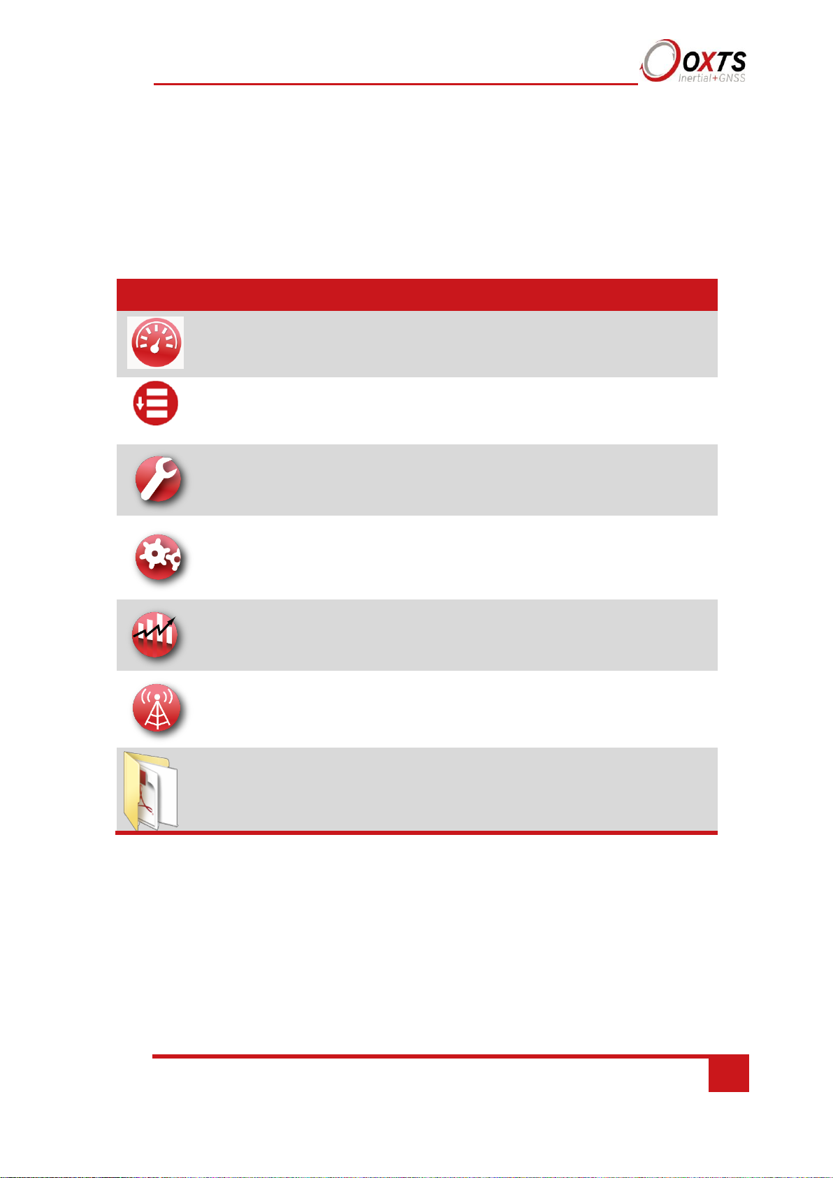
Table 6 lists the contents of NAVsuite.
Table 6. NAVsuite components
Icon
Software
Description
NAVdisplay
Used to view real-time data from OxTS products via
Ethernet or a serial port. It can also be used to transmit
special commands and replay logged data.
NAVstart
A menu from which you can navigate between OxTS
applications. This opens automatically when you are
connected to a unit.
NAVconfig
Used to create, send, and receive configurations from OxTS
products. As configurations vary between products there is
no manual for NAVconfig.
NAVsolve
Used to download raw data files from the RT and postprocess the data. The configuration can be changed and
differential corrections can be applied before the data is
reprocessed. It can export NCOM, XCOM and CSV file
formats.
NAVgraph
Used to graph NCOM, XCOM and RCOM files created in
post-process. It can display graphs, cursor tables and map
plots and data can be exported in CSV or KML (Google
Earth) format.
NAVbase
Used to configure and manage RT-Base S and GPS-Base
base stations, which can be used to achieve RTK integer
level position accuracy.
Manuals
This folder contains PDF versions of relevant OxTS
manuals. Other manuals can be downloaded from the
OxTS website.
To install NAVsuite, insert the USB stick and run NAVsetup.exe. Follow the onscreen
instructions to install the software. By default, the installer creates the program files in
C:\Program Files (x86)\OxTS on 64 bit operating systems or C:\Program Files\OxTS on 32 bit
operating systems.
The first time some OxTS applications are run, a firewall warning message similar to that shown
in Figure 1 may be triggered. This is because the program is attempting to listen for, and
communicate with, OxTS devices on the network. The firewall must be configured to allow
each program to talk on the network, or programs will not work as intended.
Page 20

20
Oxford Technical Solutions
Figure 1. Windows Firewall warning message
Ensure both Private and Public networks are selected to ensure the software can continue functioning
when moving from one type to another.
Page 21

RT User Manual
Revision: 190902
21
Hardware installation
It is essential to install the RT rigidly in the vehicle. The RT should not be able to move
or rotate compared to either GNSS antenna, otherwise the performance will be reduced.
In most circumstances the RT should be mounted directly to the chassis of the vehicle. If
the vehicle experiences high shocks, then vibration mounts may be required.
The RT is compatible with the RT-Strut product from OxTS to provide a quick and secure
vehicle mounting solution.
Do not install the RT where it is in direct sunlight as, in hot countries, this may cause the
case to exceed the maximum temperature specification.
RT orientation and alignment
The orientation of the RT in the vehicle is normally specified using three consecutive
rotations that rotate the RT to the vehicle’s co-ordinate frame. The order of the rotations
is heading (z-axis rotation), then pitch (y-axis rotation), then roll (x-axis rotation). It is
important to get the order of the rotations correct.
In the default configuration the RT expects its y-axis to be pointing right and its z-axis
pointing down relative to the host vehicle. There are times however when installing an
RT in the default configuration is not possible, for example when using the RT-Strut. The
RT can be mounted at any angle in the vehicle as long as the configuration is described
to the RT using NAVconfig. This allows the outputs to be rotated based on the settings
entered to transform the measurements to the vehicle frame.
For ease of use, it is best to try and mount the RT so its axes are aligned with the vehicle
axes. This saves the offsets having to be measured by the user. If the system must be
mounted misaligned with the vehicle and the user cannot accurately measure the angle
offsets, the RT has some functions to measure these offsets itself. The heading offset can
be measured if the vehicle has a non-steered axle. The Improve Configuration wizard in
NAVconfig should be used for this. Roll and pitch offsets can be measured using the
Surface tilt utility in NAVdisplay.
Antenna placement and orientation
For optimal performance it is essential for the GNSS antenna(s) to be mounted where
they have a clear, uninterrupted view of the sky and on a suitable ground plane, such as
the roof of a vehicle. For good multipath rejection the antennas must be mounted on a
metal surface using the magnetic mounts provided; no additional gap may be used.
The antennas cannot be mounted on non-conducting materials or near the edges of
conducting materials. If the antennas are to be mounted with no conductor below them
Page 22
22
Oxford Technical Solutions
then different antennas must be used. It is recommended to mount the antennas at least
30 cm from any edge where possible.
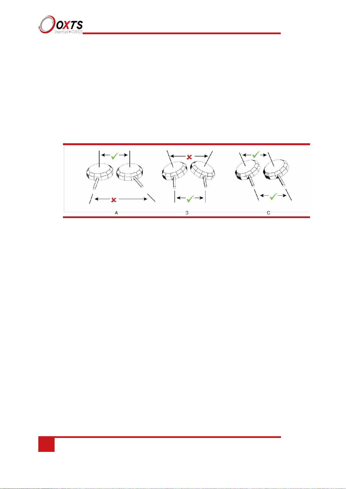
For dual antenna systems, the secondary antenna should be mounted in the same
orientation as the primary antenna, as shown in Figure 2. The antenna baseline should
also be aligned with one of the vehicle axes where possible, either inline or perpendicular
to the vehicle’s forward axis. In the default configuration the primary antenna should be
at the front of the vehicle and the secondary antenna should be at the rear.
Figure 2. Dual antenna orientations
A)
The bases of the antennas are parallel, but the cables exit in different directions. B) The cables
exit in the same direction but the bases of the antennas are not parallel. C) The bases of the antennas are
parallel and the cables exit in the same direction. This configuration will achieve the best results.
It is best to mount the two antennas on the top of the vehicle. Although it is possible to
mount one on the roof and one on the bonnet (hood), the multipath reflections from the
windscreen will degrade the performance of the system.
Multipath affects dual antenna systems on stationary vehicles more than moving vehicles
and it can lead to heading errors of more than 0.5° RMS if the antennas are mounted
poorly.
It is critical to have the RT mounted securely in the vehicle. If the angle of the RT can
change relative to the vehicle, then the dual antenna system will not work correctly. This
is far more critical for dual antenna systems than for single antenna systems. The user
should aim to have no more than 0.05° of mounting angle change throughout the testing.
(If the RT is shock mounted then the RT mounting will change by more than 0.05°; this
is acceptable, but the hysteresis of the mounting may not exceed 0.05°.)
For both single and dual antenna systems it is essential that the supplied GNSS antenna
cables are used and not extended, shortened or replaced. This is even more critical for
dual antenna systems and the two antenna cables must be of the same specification. Do
not, for example, use a 5 m antenna cable for one antenna and a 15 m antenna cable for
the other. Do not extend the cable, even using special GNSS signal repeaters that are
designed to accurately repeat the GNSS signal. Cable length options are available in 5 m
and 15 m lengths.
Page 23
RT User Manual
Revision: 190902
23
Operation
The top label and LEDs convey some basic information that aids configuration and
troubleshooting. Once power is applied, the RT requires no further input from the user to
start logging and outputting data.
This section covers some basic information required for operation of the RT.
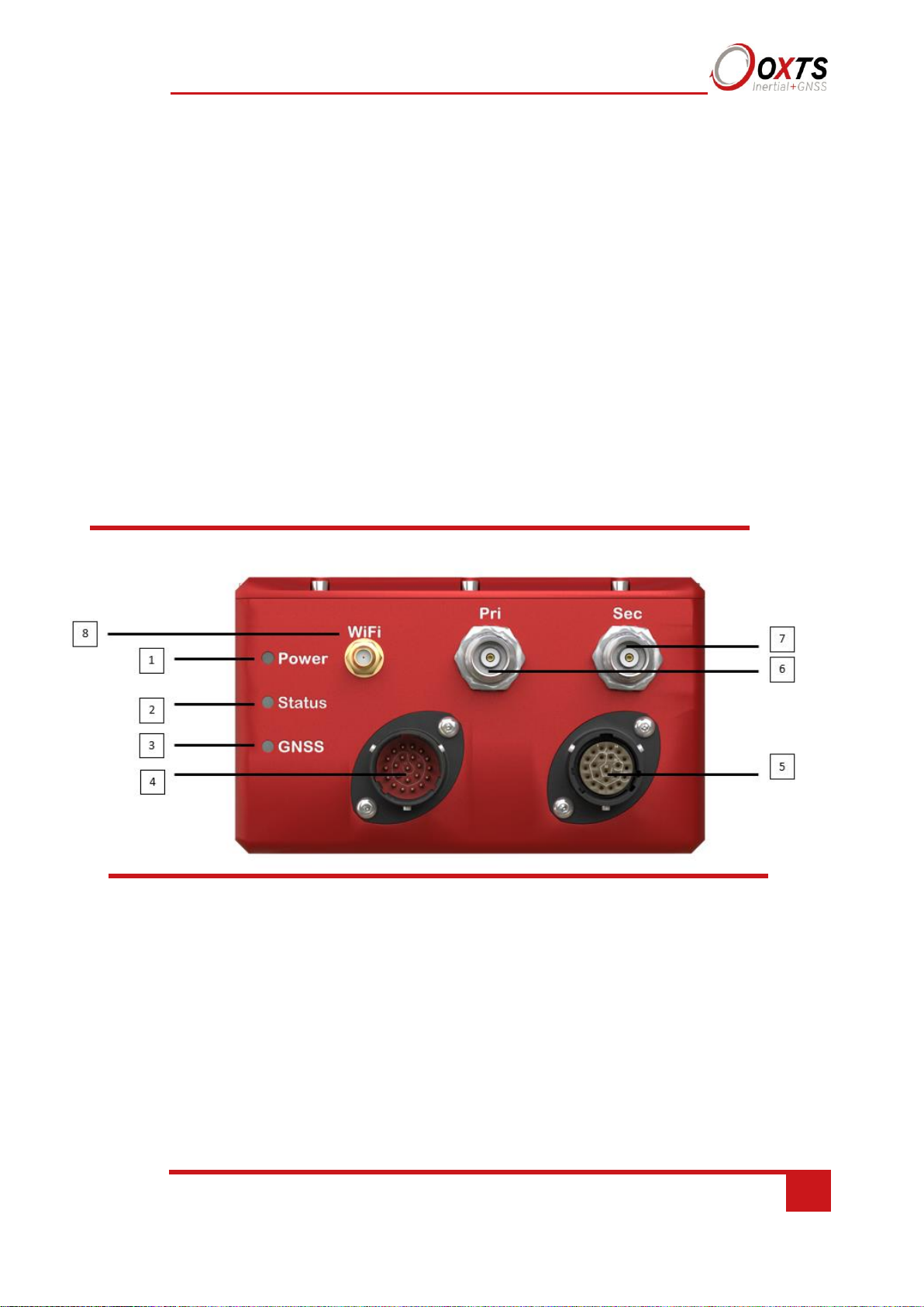
Front panel layout
Figure 3 shows the layout of the RT500 and RT3000 front panel. Table 7 lists the parts
of the front panel labelled in Figure 3. For single antenna models, the secondary
antenna connector is not connected internally.
Figure 3. RT500/RT3000 front panel layout
Page 24

24
Oxford Technical Solutions
Table 7. RT3000 v3 RT500 v1 front panel descriptions
1 Power LED
3 GNSS LED
5 Second user cable connector
7 Secondary GNSS antenna connector
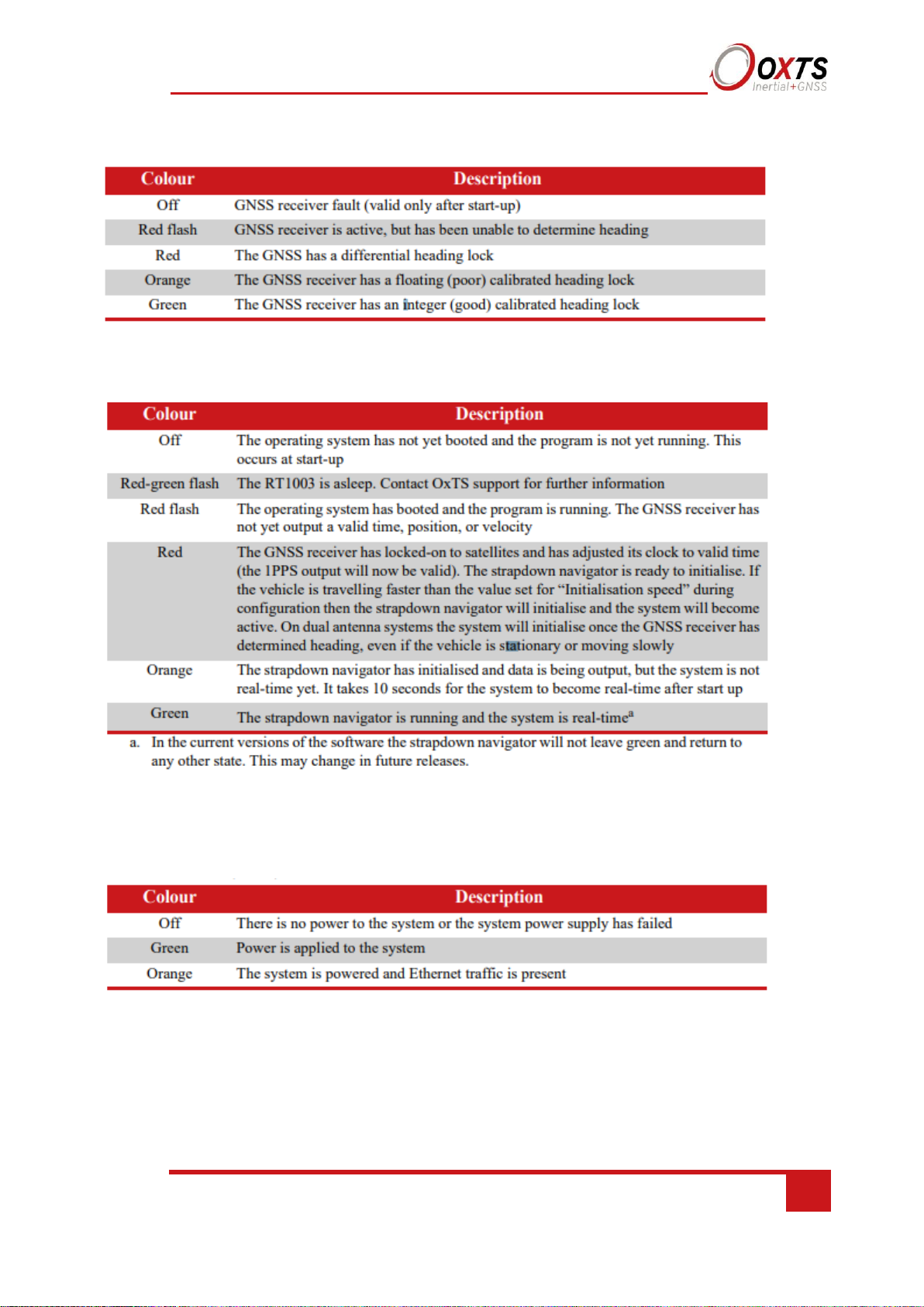
LED definitions
The LEDs on the connector panel provide information about the current system state, but it
is not possible for the LEDs to communicate everything the product is capable of measuring.
Instead, they provide a snapshot of the current status and are useful for at-a-glance checks
without the need for a portable PC. The tables below describe the behaviour of each LED.
Status LED
6 Primary GNSS antenna connector
4 User cable main connector
Label no. Description
8 WI-Fi antenna connector
Page 25
RT User Manual
Revision: 190902
25
Table 8. GNSS LED states
Table 9. Status LED states
Table 10. Power (PWR) states
Page 26

26
Oxford Technical Solutions
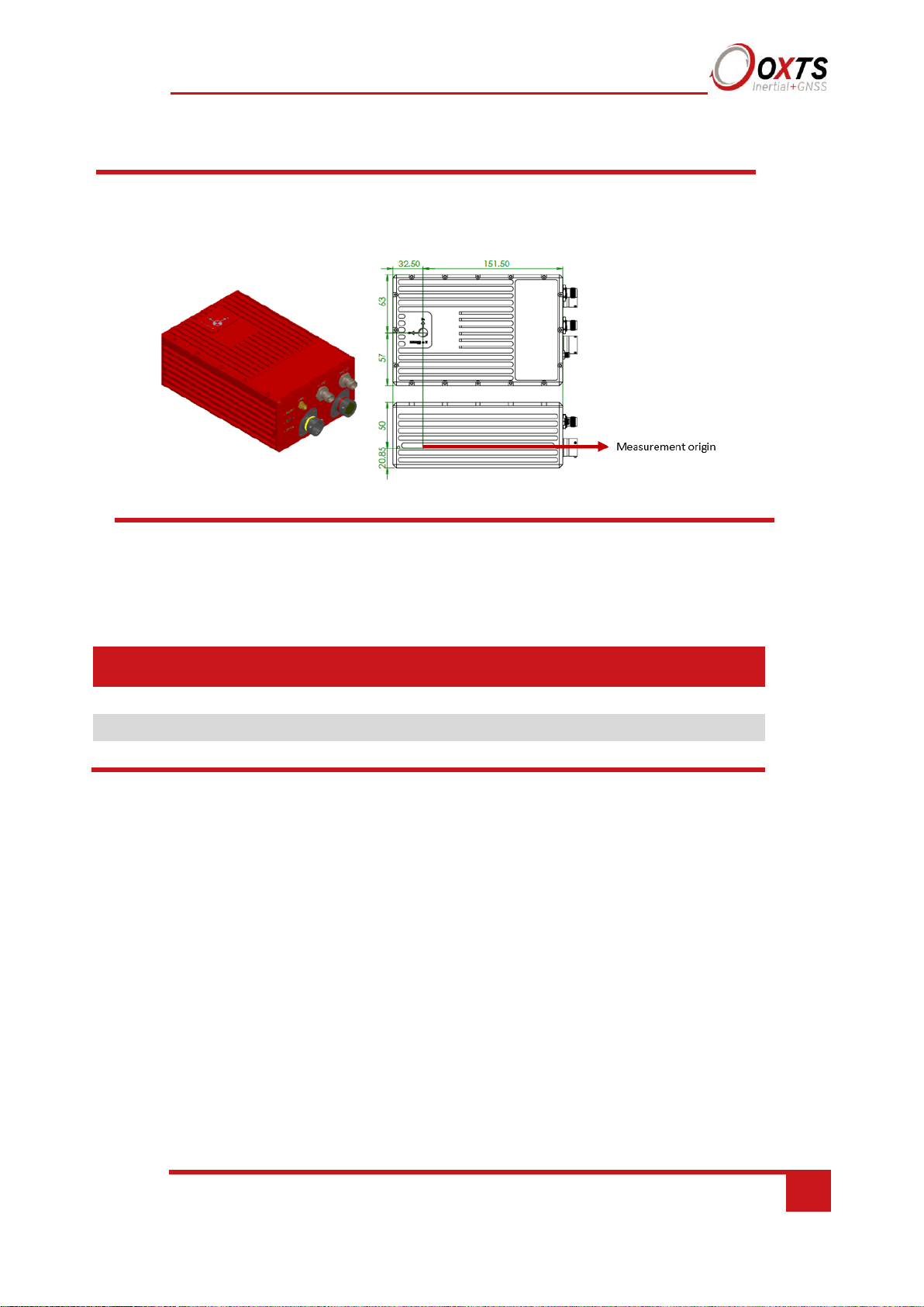
Co-ordinate frame conventions
Measurements made by the INS are available in a number of different reference frames
for use in different applications.
IMU frame
The IMU reference frame used by the RT (shown in Figure 4), is popular with navigation
systems – where the positive X-axis points forwards, the positive Y-axis points right and
the positive Z-axis points down.
When making measurements required in the configuration files, measurements should be
made between the point of interest and the measurement origin shown in Figure 4. The
axes and measurement origin point are the same for all RT models.
Page 27
RT User Manual
Revision: 190902
27
Figure 4. IMU co-ordinate frame and measurement origin
Table 11 lists the directions that the axes should point for zero heading, pitch and roll
outputs when the default mounting orientation is used.
Table 11. Direction of axes for zero heading, pitch and roll outputs
Axis
Direction
Vehicle axis
X North
Forward
Y East
Right
Z Down
Down
Once installed, if the RT axes and the vehicle axes are not the same as those listed in
Table 12, they can be aligned by reconfiguring the RT for a different mounting
orientation using the NAVconfig software.
Page 28

28
Oxford Technical Solutions
If the RT-Strut is being used to mount the RT in the vehicle then NAVconfig will have
to be used to configure the orientation or the RT will not work correctly.
OxTS NED navigation frame
Table 12. OxTS NED navigation frame definition
North The north axis (N) is perpendicular to the gravity vector and in the direction of the
North Pole along the earth’s surface.
Down The down axis (D) is along the gravity vector.
Figure 5. OxTS NED navigation frame definition
The OxTS navigation frame is attached to the vehicle but does not rotate with it. The down axis is
always aligned to the gravity vector and north always points north.
The east axis (E) is perpendicular to gravity, perpendicular to the north axis and is in
the east direction.
East
Axis Description
Page 29

RT User Manual
Revision: 190902
29
ISO 8855 ENU earth-fixed system
Table 13. ISO 8855 ENU earth-fixed system
Axis
Description
East
The east axis (E) is perpendicular to gravity, perpendicular to the north axis and is in
the east direction.
North
The north axis (N) is perpendicular to the gravity vector and in the direction of the
north pole along the earth’s surface.
Up
The up axis (U) is co-axial with the gravity vector, and positive in the up direction.
Figure 6. ISO 8855 ENU earth-fixed system
The ISO earth-fixed system is attached to the vehicle but does not rotate with it. The north and east axes
are perpendicular to the gravity vector and north always points north.
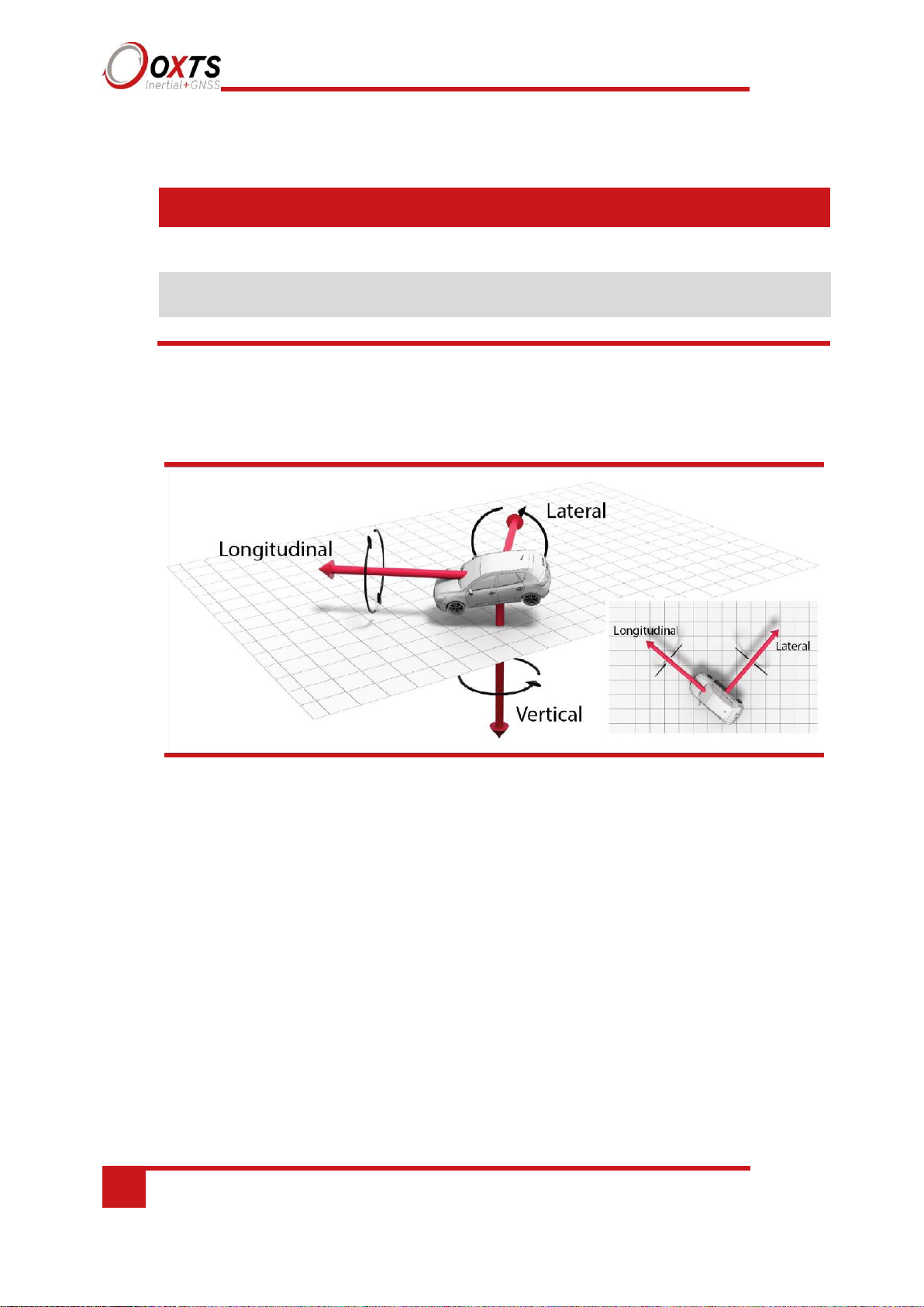
OxTS horizontal frame
The OxTS horizontal frame (sometimes called the level frame) is attached to the vehicle
but does not rotate with the roll and pitch of the vehicle. It rotates by the heading of the
vehicle. The definition of the OxTS Horizontal frame is listed in Table 14 and shown in
Figure 7.
Page 30
30
Oxford Technical Solutions
Table 14. OxTS Horizontal frame definition
Forward This is the longitudinal (forward) direction of the vehicle, projected in to the
horizontal plane.
Down This is the vertical (down) direction of the vehicle, along the gravity vector.
Figure 7. OxTS horizontal frame definition
The OxTS horizontal frame is attached to the vehicle. The longitudinal and lateral axes remain parallel to
a horizontal plane. The longitudinal axis is also parallel to the vehicle’s heading when viewed from above.
ISO 8855 intermediate system
The ISO 8855 intermediate system is attached to the vehicle but the X- and Y-axis both
remain parallel to the ground plane. The X-axis is also aligned with the vertical projection
of the vehicle heading. The definition of the ISO 8855 intermediate system is listed in
Table 15. ISO 8855 intermediate system and shown in Figure 8.
This is the lateral direction of the vehicle, pointing to the right, projected in to the
horizontal plane.
Lateral
Axis Description
Page 31

RT User Manual
Revision: 190902
31
Figure 8. ISO 8855 intermediate system
The ISO intermediate system is attached to the vehicle. The X- and Y-axes remain parallel to a
horizontal plane. The X-axis is also parallel to the vehicle’s heading when viewed from above.
Table 15. ISO 8855 intermediate system
X This is the forward direction of the vehicle, projected into the horizontal plane.
Z This is the vertical direction of the vehicle, pointing up.
OxTS vehicle frame
The OxTS vehicle frame is attached to the body of the vehicle. It is related to the INS
through the rotations in the Orientation page of NAVconfig. It can be changed while the
INS is running using the Quick Config tool of NAVdisplay. The definitions of the vehicle
frame are listed in Table 16 and shown in Figure 9.
Table 16. Vehicle frame definition
Axis
Description
X
This is the forward direction of the car.
Y
This is the right direction of the car.
Z
This is the down direction of the car.
This is the lateral direction of the vehicle, pointing to the left, projected in to the
horizontal plane.
Axis Description
Page 32

32
Oxford Technical Solutions
Figure 9. Vehicle frame definition
The OxTS vehicle frame is attached to the vehicle and rotates with it in all three axes. The X-axis remains
parallel to the vehicle’s heading, while the Y-axis points to the right and is perpendicular to the vehicle’s
vertical plane of symmetry
ISO 8855 vehicle system
The ISO 8855 vehicle system is attached to the body of the vehicle. At rest, the X-axis
points forwards horizontally and is parallel to the vehicle’s longitudinal axis. The Y-axis
is perpendicular to the longitudinal axis and points left. The Z-axis is orthogonal to the
X- and Y-axes. Definitions are listed in Table 17 and shown in Figure 10.
Table 17. ISO 8855 vehicle system
Axis
Description
X
This is the forward direction of the car.
Y
This is the left direction of the car.
Z
This is the up direction of the car.
Page 33

RT User Manual
Revision: 190902
33
Figure 10. ISO 8855 vehicle system
The ISO vehicle frame is attached to the vehicle and rotates with it in all three axes. The X-axis remains
parallel to the vehicle’s heading, while the Y-axis points to the left and is perpendicular to the vehicle’s
vertical plane of symmetry.
Ethernet configuration
To configure the RT for unrestricted data transmission it is necessary to use the Ethernet
connection. The RT 500 and RT3000 v3 also support Wi-Fi data transmission and the
setup of WiFi is covered later in this manual. The operating system at the heart of the RT
products allows connection to the unit via FTP. The use of FTP allows the user to manage
the data logged to the unit; files can be downloaded for reprocessing and deleted to make
space for future files. Configuration files for alternative configurations require FTP to
put the configuration files on to the RT. The default username and password are both
“user”.
The RT outputs its data over Ethernet using a UDP broadcast. The use of a UDP
broadcast allows everyone on the network to receive the data sent by the RT. The data
rate of the UDP broadcast is 100 Hz or 250 Hz.
In order to communicate via Ethernet each RT is configured with a static IP address that
is shown on the delivery note. If the delivery note is unavailable, the default IP address
normally takes the form 195.0.0.sn, where sn is the last two digits of the RT’s serial
number. The serial number can be found on the top of the RT or on the delivery note.
The IP address of the computer being used to communicate with the RT may need to be
changed so it matches the subnet. For example, 195.0.0.200 should be available since
this IP address is never used by the RT by default.
To change the IP address of the computer, follow these steps (applies to Windows
Vista/7/8/10):
Page 34
34
Oxford Technical Solutions
1. Open the ‘Control Panel’ from the Start menu.
2. In category view, select ‘Network and Internet’ and then ‘Network and Sharing
Centre’.
3. Select ‘Change adapter settings’ in the side panel.
4. Right-click the Ethernet option and select ‘Properties’.
5. In the window that opens, navigate the list to find Internet Protocol Version 4
(TCP/IPv4). Select it and click ‘Properties’.
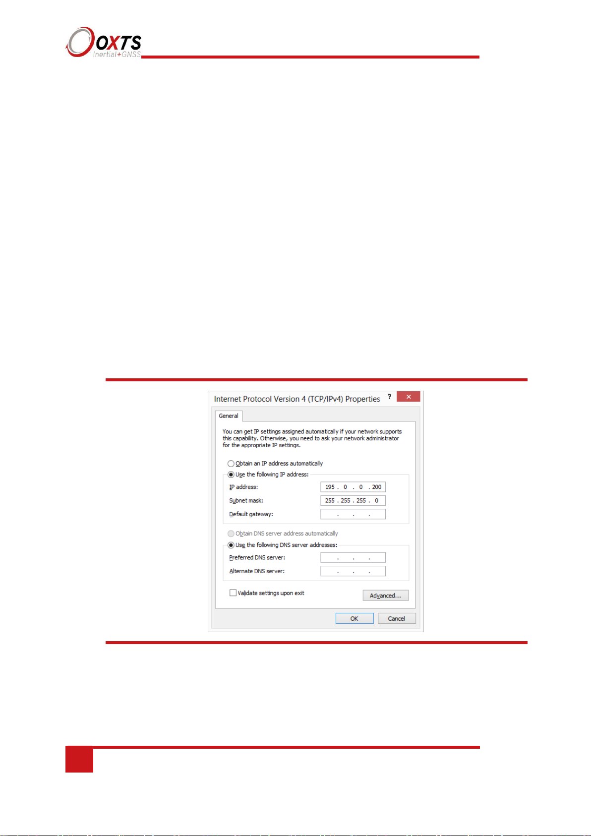
6. In the TCP/IPv4 Properties window (Figure 11), select ‘Use the following IP
address’ and enter the IP address and subnet mask to use.
7. Click ‘OK’ when finished.
Figure 11. Configuring the computer’s IP address for Ethernet data
transmission
Once the computer is configured the IP address of an RT can be found by running
NAVdisplay software; this will display the IP address of any RT connected.
Note that it is possible to change the IP address of RT systems. If the IP address has been
changed then NAVdisplay should still be able to identify the address that the RT is using,
as long as the PC has a valid IP address and this is not the same as the RT’s.
Page 35

RT User Manual
Revision: 190902
35
Connection details for Ethernet configuration
The RJ-45 connector on the 14C0038x user cable is designed to be connected directly to
a network hub. To extend the cable it is necessary to use an in-line coupler. This is two
RJ-45 sockets wired together in a straight-through configuration. Following the in-line
coupler, a normal, straight UDP Cat 5e cable can be used to connect the coupler to the
hub.
The RT can be connected directly to an Ethernet card in a computer. To do this a crossed
in-line coupler must be used. The connections in the crossed coupler are given in Table
18. Note that this is not the normal configuration sold and it may be necessary to modify
an existing coupler to suit.
Table 18. In-line coupler connections
Socket 1
Straight socket 2
Crossed socket 2
Pin 1
Pin 1
Pin 6
Pin 2
Pin 2
Pin 3
Pin 3
Pin 3
Pin 2
Pin 4
Pin 4
–
Pin 5
Pin 5
–
Pin 6
Pin 6
Pin 1
Pin 7
Pin 7
–
Pin 8
Pin 8
–
A typical in-line coupler is shown in Figure 12.
Figure 12. In-line RJ-45 coupler
Page 36

36
Oxford Technical Solutions
Wi-Fi configuration
The RT can be configured via a Wi-Fi connection using the Wi-Fi access point inside the
RT itself. Like Ethernet, the use of FTP via a Wi-Fi connection allows the user to manage
the data logged to the unit; files can be downloaded for reprocessing and deleted to make
space for future files. Configuration files for alternative configurations require FTP to put
the configuration files on to the RT.
The RT outputs its data over Wi-Fi to each device connected to its access point as a UDP
unicast message.
In order to communicate via Wi-Fi, each RT is configured with a static IP address that is
shown on the delivery note. If the delivery note is unavailable, the default IP address
normally takes the form 195.0.0.sn, where sn is the last two digits of the RT’s serial
number. The serial number can be found on the front panel of the RT or on the delivery
note.
Once you are on the same IP range as the RT you can connect to the RT via
Wi-Fi. Via your PC’s network settings you should be able to select the ‘RT as
a Wi-Fi network’. The RT that you wish to connect to can be identified by its
serial number. See Fig 14 below.
Page 37

RT User Manual
Revision: 190902
37
Figure 13. Connect to the Wi-Fi module in the RT
Wi-Fi settings are configured using NAVconfig and this process is explained
later in this manual.
Page 38

38
Oxford Technical Solutions
Dual antenna systems
It is often useful to have an understanding of how the RT uses the measurements from the dual
antenna system. This can lead to improvements in the results obtained.
1.
To use the measurements properly the RT needs to know the angle of the GNSS antennas
compared to the angle of the RT. This is very difficult to measure accurately without
specialised equipment, therefore the RT needs to measure this itself as part of the warmup process.
2.
The RT will lock on to satellites, but it cannot estimate heading so it cannot start. Either
motion or static initialisation can be used to initialise the RT.
3.
When the vehicle drives forward and reaches the initialisation speed, the RT assumes that
the heading and track are similar and initialises heading to track angle.
If the RT is mounted in the vehicle with a large heading offset then the initial value of
heading will be incorrect. This can also happen if the RT is initialised in a turn. This can
lead to problems later.
4.
When the combined accuracy of heading plus the orientation accuracy figure for the
secondary antenna is sufficiently accurate then the RT will solve the RTK Integer problem
using the inertial heading. There is no need for the RT to solve the RTK Integer problem
by searching.
If the antenna angle is offset from the RT by a lot then the RTK Integer solution that is
solved will be incorrect. For a 2 m antenna separation the RT orientation and the secondary
antenna orientation should be known to within 5°. For wider separations the secondary
antenna orientation angle needs to be more accurate.
5.
Once the RTK Integer solution is available, the RT can start to use the dual antenna solution
to improve heading. The level of correction that can be applied depends on how accurately
the angle of the secondary antenna is known compared to the inertial sensors.
6.
The Kalman filter tries to estimate the angle between the inertial sensors and the secondary
antenna. The default value used in the configuration software (5°) is not accurate enough
so that the RT can improve the heading using this value. If you want the vehicle heading
to 0.1°, but the angle of the two GNSS antennas is only known to 5°, then the measurements
from the antenna are not going to be able to improve the heading of the vehicle.
Driving a normal warm-up, with stops, starts and turns, helps the Kalman filter improve
the accuracy of the secondary antenna angle. The accuracy of this angle is available in the
verified in NAVdisplay.
Page 39

RT User Manual
Revision: 190902
39
7.
In the unlikely event that the RTK Integer solution is incorrect at the start then the
Kalman filter can update the secondary antenna orientation incorrectly. If this
happens then things start to go wrong. The Kalman filter becomes more convinced
that it is correct, so it resolves faster, but it always solves incorrectly. Solving
incorrectly makes the situation worse.
To avoid the Kalman filter from getting things wrong it is possible to drive a
calibration run, then use the Improve configuration wizard within NAVconfig. This
tells the Kalman filter it has already estimated the angle of the secondary antenna in
the past and it will be much less likely to get it wrong or change it. This step should
only be done if the RT is permanently mounted in a vehicle and the antennas are
bolted on. Any movement of either the RT or the antennas will upset the algorithms.
Multipath effects on dual antenna systems
Dual antenna systems are very susceptible to the errors caused by multipath. This can
be from buildings, trees, roof-bars, etc. Multipath is where the signal from the satellite
has a direct path and one or more reflected paths. Because the reflected paths are not
the same length as the direct path, the GNSS receiver cannot track the satellite signal
as accurately.
The dual antenna system in the RT works by comparing the carrier-phase
measurements at the two antennas. This tells the system the relative distance between
the two antennas and which way they are pointing (the heading). For the heading to be
accurate the GNSS receivers must measure the relative position to about 3 mm. The
level of accuracy can only be achieved if there is little or no multipath.
In an ideal environment, with no surrounding buildings, trees, road signs or other
reflective surfaces, the only multipath received is from the vehicle’s roof. The antennas
supplied with the RT are designed to minimise multipath from the vehicle’s roof when
the roof is made of metal. For use on non-metallic roofs a different type of antenna is
required.
When stationary the heading from the RT will show some error; the size of the error
depends on the multipath in the environment. Table 19 lists the errors to be expected
when stationary with a 1 m base-line.
Page 40

40
Oxford Technical Solutions
Table 19. Typical heading error for when stationary in different environments
Environment
Typical error (3σ)
Complete open-sky
0.6° (0.2° 1σ)
Near trees, buildings
1°
Next to trees, buildings
2°
Typical figures using a 1 m base-line. For accuracy specification of 0.1° RMS a 2 m separation is required.
Using a 2 m base-line can halve the figures shown here.
Page 41

RT User Manual
Revision: 190902
41
Inputs and outputs
RTs have two connectors for their inputs and outputs. The J1 connector of the 14C0038
user cable connects to the primary user cable and connectors J2–J7 provide connections
for the inputs and outputs. The J1 connector on the Aux user cable (secondary) provides
three additional inputs and outputs. See the user cable drawings located at the back of
this manual for more details on the connectors and pin assignments. The main connectors
are keyed so the user cable must be correctly aligned for it to connect.
The system can output data on the serial port, over Ethernet and over CAN bus. The
standard serial output of the RT is a proprietary binary format, referred to as NCOM.
OxTS offers C and C++ code that will interpret the packet. This can be used freely in
users’ programs to interpret the output of the RT. More information about NCOM can
be found in the NCOM description manual.
It is also possible to output a standard NMEA string from the RT to mimic the output of
standard GNSS receivers.
OxTS offers a service to tailor the serial output format to the customer’s specification.
Contact Oxford Technical Solutions for details of this service
Page 42

42
Oxford Technical Solutions
Digital inputs and outputs
Table 20 describes each of the signals on the digital I/O connector J5 of the 14C0038X
user cable. A more detailed explanation of each signal can be found below.
Table 20. Digital I/O signals
1PPS output
The 1PPS (J5-1) output is a pulse generated by the GNSS receiver. The output is active even
when the GNSS receiver has no valid position measurement. The falling edge of the pulse is
the exact transition from one second to the next in GPS time. The pulse is low for 1 ms, then
high for 999 ms and repeats every second. The output is a low-voltage CMOS output, with
0.8 V or less representing a low and 2.4 V or more representing a high. No more than 10 mA
should be drawn from this output.
Figure 14. 1PPS waveform
Page 43

RT User Manual
Revision: 190902
43
Trigger 1 and 2
Trigger 1 (J5-2) and Trigger 2 (J5-4) can be used to generate events within the RT for
purposes of identifying external events, or to output a time/distance-based signal for the
purpose of driving external events. Both Triggers are independently configurable in the
Options page of NAVconfig.
In input mode, the trigger waits for a signal from an external device such as a camera or
switch. When a signal is detected, a time-stamped measurement is generated by the INS in
addition to the normal measurements being generated. The trigger inputs have a pull-up
resistor so they can be used with a switch or as a CMOS input.
Input signal characteristics:
• 0 V and 5 V input
• low < 0.6 V
• high > 2.6 V
In output mode, the trigger generates pulses based on distance or in synchronisation with the
IMU clock rate. The pulse width of the distance-based signal is 1 ms, whereas the IMU sync
signal has a duty cycle of approximately 50%.
Output signal characteristics:
• 0 V and 5 V output
• low <= 0.8 V
• high >= 2.4 V
Camera mode is a software condition that is automatically entered when the PPM distance
output is configured as less than 1 PPM. It exists in order to generate time-stamped INS
measurements synchronised with distance-based output triggers. The output is called camera
mode as it’s often used to trigger image recording equipment, which can then be matched to
the position measurements at the precise moment of the trigger. Camera mode provides a
method of achieving this.
To enter camera mode, configure a trigger as an output, and set the distance to less than one
pulse per metre. A signal will be generated according to the specifications above at the
distance interval defined by the PPM settings. At the same moment the trigger signal is
output, a position measurement will be internally generated and logged alongside
the regular measurement data. To generate a real-time message in relation to the
camera trigger, it is necessary to select the ‘Output on camera trigger option’ on
the Ethernet configuration window.
Page 44

44
Oxford Technical Solutions
Wheel speed input
The wheel speed 1A input (J5-3) accepts TTL pulses from an encoder on a single wheel.
An encoder from a gearbox should not be used, and simulated TTL pulses (e.g. converted
from the CAN bus) should not be used either. The timing of the wheel speed input pulses
is critical and nothing should cause any delay to them.
The RT also accepts signals from quadrature wheel speed sensors. When using quadrature
sensors, connect one channel from the quadrature sensor to wheel speed 1A, and the other
to wheel speed 1B input (J5-5). The odometer input should be configured as per a normal
wheel speed sensor – the RT will automatically detect the use of the quadrature sensor.
The wheel speed input requires less than 0.8 V for a low pulse and more than 2.4 V for a
high pulse. Limited protection is provided on this port, however the input voltage should
not exceed 12 V.
Wheel speed input signal characteristics:
• 0 V to 12 V
• low < 0.8 V
• high > 2.4 V
The wheel that is used should not steer the vehicle. The RT will assume the wheel travels
straight.
IMU sync output pulse
The synchronising edge of the PPS is configurable in NAVconfig.
Page 45

RT User Manual
Revision: 190902
45
Configuring the RT
To obtain the best results from your RT it will be necessary to configure the RT to suit
the installation and application before using it. The program NAVconfig can be used to
do this. This section describes how to use NAVconfig and gives additional explanations
on the meanings of some of the terms used.
It is only possible to change the RT configuration using Ethernet or WiFi. It is necessary
to have the Ethernet and Wi-Fi adaptor settings on your computer configured correctly
in order to communicate with the RT and change the settings. See the sections “Ethernet
configuration” and “WiFi configuration” on pages 36 and 37 for
more information.
Overview
In order to give the best possible performance, the RT needs to know the following
things:
• The orientation of the RT as it is mounted in the vehicle.
• The position of the primary GNSS antenna compared to the RT.
• The orientation of dual antennas (if applicable) compared to the RT.
• The position of the rear wheels (or non-steering wheels) compared to the RT.
• Some environment parameters.
The RT can work out many of these parameters by itself, but this takes time. Measuring
the parameters yourself and configuring the RT reduces the time taken to achieve full
specification.
RT products can calculate the position of the GNSS antenna. This works well when using
a base station to achieve 1 cm accuracy, but can take hours with less accurate positioning
modes. It is best to measure the position of the GNSS antenna to an accuracy of 10 cm
or better.
If the RT has been running for some time, it will have improved the measurements. It is
possible to read these improved measurements into NAVconfig, commit them to the RT,
then use them next time you start the system. If you move the RT from one vehicle to
another it is essential you create a new configuration rather than using parameters that
have been tuned for a different vehicle.
Page 46

46
Oxford Technical Solutions
Working through NAVconfig
NAVconfig is split into seven sections. Each section contains several tabs with settings
that can be applied to the device. The sections are: Home, Ready Configuration,
Hardware Setup, Interfaces, Environment, Advanced Tools and Write Configuration.
When a device is connected via WiFi or Ethernet, the product name (including serial
number) will be displayed at the top of the application. By clicking on the ‘Save’ icon at
the top right of the application you can save your configuration process to a destination
on your computer. This can be done at any stage.
NAVconfig supports English and Chinese (simplified) languages.. You can switch
language in NAVconfig by clicking on the ‘Settings’ button at the bottom left of the
window and choosing your preferred language from the options.
If you are connected to a device or editing a configuration file from an RD file then it is
possible to view information related to the device in NAVconfig. Click the ‘i’ icon in the
bottom left of the window to see a list of features related to your device.
NAVconfig Home section in NAVconfig
NAVconfig is a universal tool that is used to configure many different devices. The first
step is to choose whether you are starting a new configuration, modifying an existing
configuration or improving a configuration after a device warm-up.
When you select ‘New configuration’ you must then go through each step of the
configuration wizard in order before committing a new configuration to the device.
When you select ‘Modify configuration’ you can jump in and edit the configuration,
navigating through all the options in any order before committing the changes.
Selecting “Improve configuration” sets up a different workflow within NAVconfig for
users who have completed a device warm-up and want to apply improved settings to the
device and recommit these settings.
Page 47

RT User Manual
Revision: 190902
47
Figure 15. NAVconfig Home section
Start/Read Configuration section in NAVconfig
Figure 16. NAVconfig Start/Read Configuration section
Page 48

48
Oxford Technical Solutions
This section becomes available when you choose “New configuration” or “Modify
configuration” from the Home section. It is important to ensure the correct Product type
and version is selected. The settings available in NAVconfig vary depending on the
product type and version chosen.
The product model and generation (version) can be found on the label on your product.
Read Configuration section
The Read Configuration choice tells NAVconfig where to read the initial configuration
from (see Figure 18).
Figure 17. NAVconfig Read Configuration section
Read settings from a folder: It is possible to store a configuration in a folder. The
configuration comprises several files, so it is tidier to keep it in a folder by itself. To read
the configuration from a folder, select this option and then specify a folder by clicking
the ‘Browse…’ button.
Page 49

RT User Manual
Revision: 190902
49
‘Read settings from a raw data (RD) file:’ The RT writes the configuration it is using to
the internally stored RD file. This option extracts the configuration used and loads it into
the configuration wizard. Specify an RD file by clicking the ‘Browse’… button.
Read initial settings from device: If the RT is connected to the computer via Ethernet or
WiFi it is possible to read the initial settings directly from the RT. The settings loaded are
the settings that were last committed to the RT using NAVconfig or the factory default
settings applied at manufacture stage. Select this option and enter the correct IP address of
your RT or select it from the dropdown list.
You must also specify the type of vehicle that the device is being installed in. This will
tailor the settings available to edit in NAVconfig.
Hardware Setup section in NAVconfig
This section contains settings related to the position and orientation of the RT in the vehicle
and the GNSS antennas as well as the profile of the vehicle in which the RT is being
installed (position of axles). It is broken up into tabs and it is recommended that you work
through each tab in order.
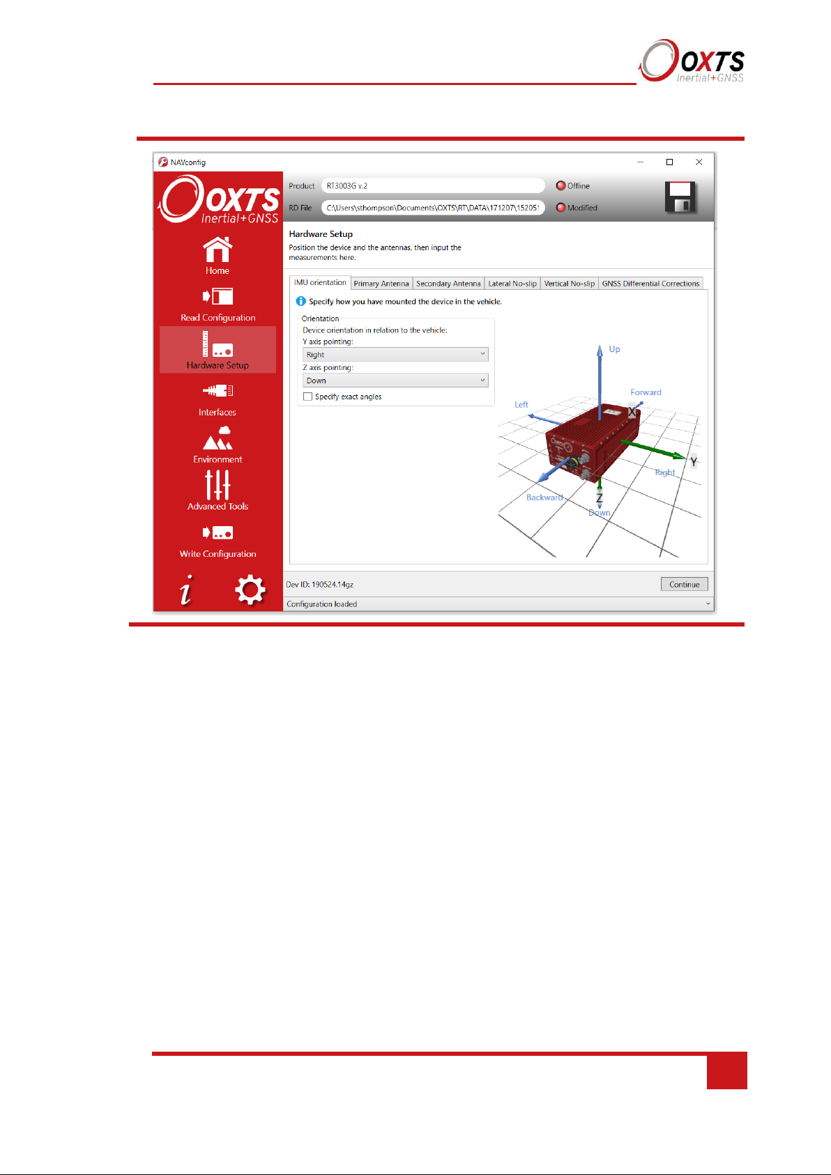
IMU orientation tab
The IMU orientation tab is used to define the vehicle co-ordinate frame relative to the
RT’s co-ordinate frame. It is important to get the orientation correct as although settings
entered on this page do not affect the accuracy of the RT, if the outputs are not properly
rotated to the vehicle frame then the measurements will appear incorrect.
When using an RT-Strut, the orientation will need to be changed. Figure 19 shows an RT
mounted on an RT-Strut in a vehicle. In this configuration, the y-axis points left and the
z-axis points forwards. Other configurations are possible with the RT-Strut.
Page 50

50
Oxford Technical Solutions
Figure 18. An RT device mounted on our RT-Strut
Use the Y axis points and the Z axis points box to specify which way the RT’s axes point
in the vehicle. Figure 4 shows the RT axes’ directions. The IMU orientation tab of the
configuration wizard, also has illustrations to visualise the orientation of the RT in a vehicle
based on the settings input. The advanced settings will change to show the three rotations
associated with orientation input, even when unavailable.
Page 51
RT User Manual
Revision: 190902
51
Figure 19. NAVconfig IMU orientation tab in the Hardware Setup section
For correct initialisation, it is necessary to get the heading orientation correct.
The RT gets its initial heading by assuming the vehicle is travelling forwards in
a straight line. If the definition of the vehicle’s x-axis (forward direction) is
incorrect in the RT then it will not initialise correctly when the vehicle drives
forwards.
If the vehicle level option is used, then the pitch and roll orientations must also
be correct.
To make small adjustments, select the ‘Specify exact angles’ checkbox to enable
the rotations for editing. This allows any slip angle, pitch or roll offsets to be
zeroed.
Primary antenna tab
The RT can calculate the position of the primary antenna itself. However, this takes time
and better results can be achieved sooner if the user measures the distance accurately.
Getting these measurements wrong is one of the main reasons for poor results from the
RT, so it is important to be careful. It is recommended to measure the GNSS antenna
position to an accuracy of 10 cm or better. Figure 21 shows the Primary Antenna page.
Page 52

52
Oxford Technical Solutions
Figure 20. NAVconfig Primary Antenna tab
It is necessary to tell the RT the distance between its measurement origin (shown in Figure
4) and the GNSS antenna’s measurement point. This should be entered in the vehicle’s
co-ordinate frame.
The RT will try to improve the position of the primary GNSS antenna during use. To use
the values the RT has estimated use the “Improve configuration” wizard after your warmup on the Orientation utility page.
Page 53

RT User Manual
Revision: 190902
53
Secondary Antenna tab
If your system has two antennas, click the ‘Secondary GNSS antenna’ checkbox on the
Secondary Antenna page (Figure 22) to allow the configuration to be entered. If it is not
enabled, the RT will ignore the secondary antenna and will not use it to compute a
heading solution.
Enter the antenna separation and select to position of the secondary antenna relative to
the primary antenna from the dropdown list. The illustrations will change according to
the settings you choose to help visualise the configuration of the antennas.
Figure 21. NAVconfig Secondary Antenna tab in the Hardware Setup section
Page 54

54
Oxford Technical Solutions
The RT does not estimate the distance between the two antennas. It is essential to get
this right yourself, otherwise the system will not work correctly and the performance
will be erratic. The measurement needs to be accurate to 5 mm, preferably better than 3
mm.
A wider separation will increase the dual antenna heading solution accuracy. The
maximum recommended separation is 5 m, giving an accuracy of up to 0.05° in both
static and dynamic conditions.
If the antennas are mounted at significantly different heights, or if the mounting angle
is not directly along a vehicle axis (forward or right), then click the ‘Use advanced
settings’ checkbox to enable advanced settings and specify the orientation and height
offset.
Getting the angle wrong by more than 3° can lead the RT to lock on to the wrong heading
solution. The performance will degrade or be erratic if this happens. If the angle between
the antennas cannot be estimated within a 3° tolerance then contact OxTS support for
techniques for identifying the angle of the antennas.
The ‘Enable static initialisation’ option is useful for slow moving vehicles or where it is
essential to start the RT running before moving (for example in autonomous vehicles).
Static initialisation is 99% reliable in open sky, but the reliability decreases in
environments with high multipath. Static initialisation is also faster when the antenna
separation is smaller. This can be configured in the Environment section.
The RT will improve the estimate of the secondary antenna orientation settings. Use the
“Improve configuration” option to use the improved values.
Lateral No-slip and Vertical No-slip tabs
This feature uses characteristics of land vehicle motion to improve heading and slip
angle and to reduce drift. Specifying the position of the non-steered wheels makes a
huge difference to the lateral drift performance of the RT when GNSS is not available.
This feature must be disabled for airborne and marine systems where the lateral velocity
can be significant. This feature is also not suitable for land vehicles that use all wheels
to steer, i.e. no fixed wheels. The vertical settings should not be used if the vehicle can
perform wheelies.
Page 55

RT User Manual
Revision: 190902
55
The Lateral No-slip feature applies heading correction when the land vehicle is not
slipping. When the vehicle is slipping the lateral acceleration is usually large enough that
the normal heading corrections provide excellent results. When combined with a wheel
speed input the drift of the RT when GNSS is not available is drastically reduced.
Figure 22 shows the Lateral No-Slip tab.
Figure 22. NAVconfig Lateral No-slip tab in the Hardware setup section
For the Lateral settings, the system needs to know the position of the non-steered axle
(rear wheels on a front-wheel steering vehicle and vice versa). A position at road
height, mid-way between the rear wheels should be used as shown in Figure 22.
Vehicles with all wheels steering cannot use this feature reliably, although minor
steering of the rear wheels does not significantly affect the results.
Page 56

56
Oxford Technical Solutions
Figure 23. Measurement point for Lateral No-slip
Measuring from the RT, measure the distances to the non-steered axle position in each
axis in the vehicle co-ordinate frame. Select the direction from the dropdown lists and
enter the distances.
The measurements are made to an accuracy of 10 cm. Selecting an accuracy better than
10 cm does not improve results. Using an accuracy figure worse than 20 cm will increase
the drift of the RT. Use the Accuracies tab in the Advanced Tools section to specify
measurement accuracies individually.
The Lateral No-slip feature also requires some knowledge of the road surface. Select
one of the predefined options from the dropdown list, Normal or Low friction (ice).
For the Vertical No-Slip, the system needs to know the position of the front axle. A
position at road height, mid-way between the wheels should be used, like for the rear
axle.
Measure the distances again from the RT and enter them into the cells, selecting the
appropriate directions from the dropdown lists.
Page 57

RT User Manual
Revision: 190902
57
Figure 24. NAVconfig Lateral No-slip tab in the hardware Setup section
When using No-Slip features, the RT can estimate the slip angle offset of the
RT compared to the vehicle. After the RT is initialised and warmed-up, use the
Improve configuration option from the NAVconfig Home section to
automatically read the RT’s slip angle offset estimate. This ensures a slip angle
of zero is measured when driving straight on a level track.
Page 58

58
Oxford Technical Solutions
GNSS Differential Corrections tab
An RT can be configured to use several different differential correction message types on
connector J3. Figure 25 shows the Differential corrections properties window and Table 21
gives details on the correction types available.
Figure 25. NAVconfig Differential corrections tab in the Hardware Setup section
Page 59

RT User Manual
Revision: 190902
59
Table 21. NAVconfig Differential Correction formats
RTCA RTCA is the standard adopted for aircraft. It was the first open standard to use 1 cm
corrections. The RT-Base S and GPS-Base products use RTCA.
RTCMV3 RTCMV3 is the latest version of RTCM. This option gives the best accuracy and
should be used if your differential corrections are in Version 3 format.
Advanced. This option is reserved
Select the Correction format you wish to use from the box and then select the baud rate
from the Serial port settings (radio modem). The most common baud rates used for
differential corrections are 4800 baud and 9600 baud. The RT-Base S and GPS-Base use
9600 baud. The values in the Data bits, Parity and Stop bit fields should be set to match the
incoming signal.
NTRIP
When selected, the “Enable NTRIP corrections” checkbox box configures the RT for
RTCMv3 corrections and sends an NMEA GGA message out from J3 back to the NTRIP
server.
The RT3000 v3 and RT500 house an internal NTRIP client. Select ‘Use Internal Client’ to
configure the settings of the NTRIP client inside the RT.
Correction type Description
This is a standard adopted by Trimble. The RT products support both CMR
and CMR+ formats.
CMR
RTCM is the most common open standard used for differential corrections.
RTCM
Page 60
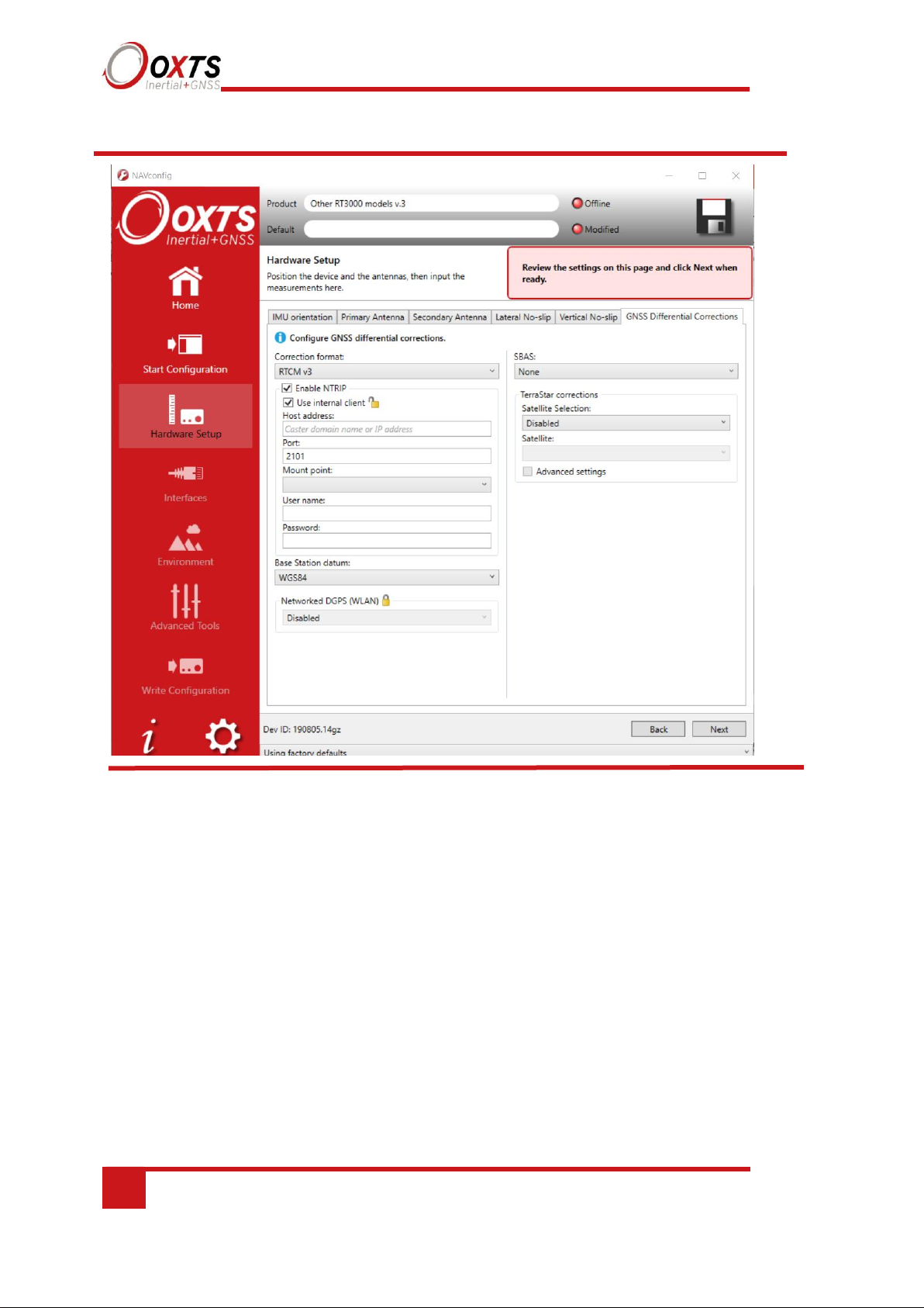
60
Oxford Technical Solutions
Figure 26. NTRIP Internal Client
When the ‘Use internal Client’ option is selected, several additional settings are provided and need
to be configured.
The Host address needs to be entered to receive corrections. This is the domain name or IP address
of the caster or service that will be used. This should be provided by the service provider.
The Port is set to 2101 by default. The port should not be changed, or corrections will not be received
by the unit.
The Mounting point can be selected from the list available. This list will automatically populate,
unless the service provider requires authentication when collecting the information. If the NTRIP
service is protected by a login, the list of mounting points will have to be accessed manually and
the mounting point typed into the field.
The User name and password for the correction stream need to be inputted for the RT to be able to
receive the data from the caster. Please note that this is not the same user name and password as the
account held with the service provider.
Page 61

RT User Manual
Revision: 190902
61
Networked DGPS (WLAN)
The Networked DGPS (WLAN) controls allow an RT to be configured to broadcast or
receive differential corrections over WiFi when connected to an RT-XLAN. When
Network correction transmitter is selected, an RT will broadcast differential
corrections it is receiving via a radio modem from an OxTS base station, using its RTXLAN. Other RT devices that are on the network as the broadcasting RT, will then be
able to receive the DGPS messages and use them. To do this, the Network correction
receiver option should be selected on those devices, and the IP address of the system
carrying the radio modem should be selected from the box. Using this system reduces
complexity in situations where multiple RTs need DGPS corrections as only one pair of
radio modems needs to be used.
Networked DGPS (WLAN) can also use corrections received via NTRIP, rather than a
local base station. As before, the RT that is connected to the NTRIP server should be
configured with Network correction transmitter selected. Other RTs should be configured
with Network correction receiver selected, and the IP address of the system that is
configured as the transmitter should be selected in the box.
Regardless of whether DGPS corrections are received via NTRIP or a local base station,
only RTCMv3 corrections are currently supported in networked DGPS mode.
SBAS
In Europe, North America, and Japan SBAS can be used for differential corrections.
These services will improve the position accuracy of the RT. In North America the SBAS
service is known as WAAS, in Europe it is known as EGNOS and in Japan it is known as
MSAS. Select the option that is most suitable for the territory you are in.
TerraStar corrections
TerraStar corrections are configured on the GNSS Differential Corrections tab within the
Hardware Setup section. You can choose between Manual or Automatic Satellite
Selection and if you choose Manual you can select from a list of available options. Using
the “Advanced Settings” checkbox you can also change the frequency and baud rate.
Page 62

62
Oxford Technical Solutions
Interfaces section in NAVconfig
This section contains options for configuring the interfaces of the RT. Some of these
settings are feature code controlled so may not be visible to all users on all devices.
Ethernet tab
The Ethernet settings include configuring the Ethernet data output rate, packet type
and Triggers for the RT. You can also enable the Driving Robot interface and input the
Driving robot IP if you are using a Driving robot with your RT.
The Ethernet output can either output NCOM or MCOM, or be disabled by using the
Output packet dropdown list. When NCOM or MCOM is selected, the Data rate can be
selected by using the dropdown list.
If a trigger has been configured as an event input, click the ‘Output’ on falling edge of
trigger or Output on rising edge of trigger checkboxes to choose when the extra data
packet is generated. If a trigger has been configured as an output trigger, click the
‘Output on camera trigger’ to generate extra data packets based on the output trigger
settings configured earlier. These packets are interpolated to the time when the event
occurred and may be output up to 30 ms late and out of order compared to the normal
messages.
It is essential to enable these options in order to see trigger information in NCOM, or if
the events have a rate higher than 1 Hz otherwise the output cannot communicate all of
the events and some will be lost.
For the Driving robot, the default address (195.0.0.100) is listed in the dropdown list but
can be changed if required by typing the correct address. When the ABD Steering Robot
is enabled, the output smoothing is automatically enabled too.
Page 63

RT User Manual
Revision: 190902
63
Wi-Fi tab
To configure the Wi-Fi as an Access Point, click on the option and the field to configure
the Network details and router details will become available to edit.
The Network name (SSID) will be by default OxTS INS (SN) This can be changed to
another name but cannot contain any of the following characters: [<], [>], [&], ['] and ["].
It is possible to add a password to the network created. To enable this, select what security
protocol to use, WPA or WPA2, and then enter the Passphrase.
For the router, the Gateway and Subnet mask can be changed if using a different IP range
or to prevent IP clashes. The Gateway as referred to in NAVconfig is the IP address of
the Gateway or Wi-Fi module in the RT.
To Configure the Wi-Fi to connect to an existing WLAN, you will need to have the WiFi already enabled and have the Access Point disabled. If the Wi-Fi is not enabled, the
RT will not be able to see what network it could connect to. If the Access Point is enabled,
the RT will not connect to an existing network.
Under “Wireless networks in range of device”, you can choose which network you wish
to connect the RT to and drag the network to the box on the right. If the network is
secured, a text box will be available to enter a password. This will contain the networks
that the RT will connect to when they are in range.
Warning:
A network containing the following characters, [<], [>], [&], ['] and ["], will not be seen
correctly and the RT will not be able to connect to the device. These characters cannot
be used in the SSID of the RT.
If using an iPhone to hotspot, please be aware if the phone is called "[name]'s iPhone" as
this has the non-usable [']. To change the name of the hotspot, go to "Settings" >
"General" > "About" and select "Name".
Page 64

64
Oxford Technical Solutions
CAN Output tab
RT systems can be configured to send and receive data via a CAN bus. This allows RT
data to be sent to external logging devices, and signals from a test vehicle’s CAN bus to
be logged alongside navigation data inside an RT.
By default, CAN communication is disabled. It is enabled by selecting the Enable CAN
interface checkbox (see Figure 28). The default version is CAN 2.0. CAN-FD is also
available.
Figure 27. NAVconfig CAN output configuration tab
You can select individual messages or enable all messages by choosing them from the table
displayed.
Depending on the baud rate selected, the suggested maximum CAN messages per second will
change. A warning message will appear if the combined rate of all current navigation and status
messages will overload the CAN bus at the selected baud rate.
Page 65

RT User Manual
Revision: 190902
65
Disabling or reducing the frequency of navigation or status messages will remove the
warning and ensure reliable operation of the CAN bus. Increasing the baud also works,
but the baud rate must be common to all devices on the bus. When using an RT-ANA,
the default baud rate is 1 MBaud.
The Export DBC file button generates a CAN DBC library listing all navigation and
status messages that are enabled (not greyed-out). The DBC file does not include
channels defined under the acquisition tab. The navigation status message binary format
is described from Table 31 onwards. The status message binary format is the same as
the NCOM status message binary format as described in the NCOM Description
manual. Those status messages that do not have signals listed against them are not
described at the signal level in the DBC file. The binary format of these messages is
quite complex and as such the DBC file it not sufficient to describe the decoding process.
The Navigation tab is where navigation-related CAN messages are configured for
output. The table can be sorted in ascending or descending order by clicking any column
header. This is particularly useful when checking for enabled/disabled messages.
Figure 28. NAVconfig CAN Output configuration tab – Navigation
Page 66

66
Oxford Technical Solutions
Each message can be enabled/disabled by clicking in the appropriate cell and selecting
from the dropdown menu. The message Identifier is also changed by clicking in the cell.
The identifier number should be defined in either hexadecimal or decimal format. Decimal
values can be entered as normal. Hexadecimal values should have a letter “h” appended.
The Data rate can be set using the dropdown list that appears after clicking in each data
rate cell. When a message’s data rate changes or it is enabled or disabled, the caption at the
bottom of the window displaying messages per second updates to reflect the new settings.
The Enabled checkbox quickly enables and disables all messages.
The Status tab lists all status messages, which are sent one after another in a repeating
loop. Although 80 messages are shown in the list, 100 are actually used internally. If the
data rate is set to 100 Hz, a status message will be sent every 10 ms. Some messages are
transmitted more frequently than others because they appear in the list more than once. At
a data rate of 100 Hz, each message in the Status tab will be transmitted on the CAN bus
once per second.
The Prefix and Suffix boxes can be used to quickly add alpha-numeric strings to the
beginning and end of all message names, while the Identifier offset box allows users to
quickly apply an offset to all CAN IDs. These tools are useful when IDs conflict with other
equipment and changes need to be made to many channels.
Positive and negative integer values can be entered into the Identifier offset box in both
decimal and hexadecimal formats. Data entered in hexadecimal format should end with an “h”.
To remove the offset, type 0 in the identifier offset box.
The Enabled checkbox quickly enables and disables all status messages.
The Message name, Signal name and Units can be edited in the table. Changes made using
NAVconfig are independent of the DBC file, and will not affect it or be saved.
Page 67

RT User Manual
Revision: 190902
67
CAN FD (CAN with Flexible Data-Rate) is an extension to the original CAN bus protocol
specified in ISO 11898-1. CAN FD was created to accommodate increases in bandwidth
requirements within automotive networks. The CAN FD protocol has brought the software
closer to “real time” through the minimisation of delays between an instruction and transfer
of data (latency) and higher bandwidth.
Enable CAN-FD by selecting it from the CAN version dropdown. Figure 29 displays the
options available when configuring the RT for CAN-FD output.
Figure 29. CAN-FD output configuration
Choose a Nominal bit rate from the dropdown list.
If you want to adjust the Flexible data rate, select the checkbox and then you can choose
the Data bit rate from the additional dropdown list and specify the sample points.
Page 68

68
Oxford Technical Solutions
CAN Acquisition tab
The CAN Acquisition tab is where incoming CAN signals are defined. These signals can
be viewed in real time along with the RT’s native data using NAVdisplay, or later using
NAVgraph.
Channels are added to the acquisition list by clicking on the ‘Load DBC file’ button and
selecting a valid CAN DBC file. The top 12 messages in the list acquisition list are logged
at the INS update speed of 100 Hz or 250 Hz. This is not adjustable.
The Message name, Signal name and Units can be edited in the CAN Signal Properties
window (Figure 30). This is opened by double-clicking any signal. Changes made using
NAVconfig are independent of the DBC file and will not affect it or be saved.
Figure 30. CAN Acquisition tab
Page 69

RT User Manual
Revision: 190902
69
Serial 1 Output tab
The serial port can be configured to output different types of message (see Table 22).
Select a Packet type and Baud rate. By default, data on the serial port is output using 8N-1, although odd/even parity and two stop bits are available by using Advanced
commands. Please contact support@oxts.com for details on this.
If the NMEA packet type is selected, the NMEA tab will appear in the properties window.
In this tab the NMEA messages to output on the serial port are selected by choosing the
data rate for each message type from the dropdown lists and clicking the checkbox for
when to generate the message.
NMEA messages can also be generated in response to event input triggers. Check the
falling or rising edge checkbox to compute the message when the event occurs. The RT
can also generate NMEA messages from pulses on the output trigger. These messages use
interpolation to compute the values at the exact time of the event but may be output on
the serial port up to 30 ms late and out of order compared to the normal messages. To
enable these messages check the appropriate checkbox.
Page 70

70
Oxford Technical Solutions
Table 22. Serial outputs
Note that it is easy to overload the serial port if there are too many events. The software
computes the number of characters that will be output each second and displays this at
the bottom of the window. A serial port data overflow warning message will appear if the
data rate is too high for the selected baud rate; to fix this it is necessary to lower the data
rate of the selected NMEA sentences or increase the baud rate.
Selecting “Allow extended length messages” enables the full GGA and RMC messages
to be output, which are longer than the NMEA specification allows. Please see the NMEA
0183 Description manual for more details. Selecting “Output approximate values before
initialisation” forces output of the raw GNSS measurements before the RT is initialised.
Currently just the position is output and this is the position of the antenna, not the inertial
measurement unit. Note that there will be a jump (from the antenna to the inertial
measurement unit) when initialisation occurs.
Page 71

RT User Manual
Revision: 190902
71
Analogue tab
The Analogue option is used for configuring the RT-ANA companion product. There are
16 channels in the RT-ANA, numbered from 0 to 15. The Measurement, Range, and Min
and Max values for all 16 channels can be configured. Click on a specific cell to change
the settings.
Note: The CAN bus must be configured correctly for the analogue outputs to work
correctly.
PPS / Triggers tab
The output trigger on the digital I/O generates a pulse based on distance. Select the distance
interval to generate the pulses on from the dropdown list, or type in a value. The output has
0.8 V or less for a low and 2.4 V or more for a high. The pulse width is 1 ms.
NAVconfig Environment section
This section contains settings related to the environment you will be collecting data in,
including the device initialisation conditions. This section is not broken down into tabs but
contains several selectable options and pre-defined values on one screen.
Initialisation
Static initialisation is disabled by default.
If static initialisation has not been enabled, the RT will need to be initialised by driving
forwards in a straight line to initialise the heading to the track angle. The initialisation
speed is the speed at which the vehicle must travel to activate the initialisation.
The default initialisation speed is 5 m/s. However, some slow vehicles cannot achieve this
speed. For these vehicles adjust the initialisation speed to a different value.
If a speed less than 5 m/s is selected, then care should be taken to make sure that the RT is
travelling straight when it initialises.
Vehicle starts
Select a predefined value from the dropdown list.
If you know the vehicle will be level when starting (to within about 5°) select ‘Level’. This
saves about 40 s during the initialisation process since the RT does not have to take the time to
compute an initial roll and an initial pitch. In high vibration environments Not Level may not
work and so the RT can only start if the vehicle is level and the Level option has been specified.
Page 72

72
Oxford Technical Solutions
GNSS environment
Select a predefined value from the dropdown list.
If the system is used predominantly in open-sky, then the Open skies setting should be
used. In environments with a lot of GNSS multipath then Some obstructions or Frequent
obstructions can be used depending on the environment. This will allow less accurate
GNSS measurements to update the system and it also places more reliance on the inertial
sensors compared to the GNSS.
Unless the open-skies setting is used, the RT will not report accuracies that meet its
specifications.
Vibration levels
Select a predefined value from the dropdown list.
The Normal vibration level is adequate for most circumstances. The RT is very tolerant
of vibration and has been used successfully in environments with more than 2 g RMS
using the Normal setting. If the velocity innovations are very high, and many GNSS
packets are being dropped, then this setting can be changed.
Typical situations where the High vibration setting should be used include those where
vibration mounts have been used, or where the RT and the antenna are mounted on
different sprung parts of the vehicle (e.g. the cab/chassis of a truck).
Heading lock
The heading of single antenna systems can drift when the RT remains stationary for long
periods of time. To solve this, the RT includes an option to lock the heading to a fixed
value when stationary. This option cannot be used if the vehicle can turn on the spot (i.e.
with no forward velocity). With heading lock enabled the RT can remain stationary for
indefinite periods of time without any problems. For vehicle testing this option is
recommended.
There are four settings to choose from. Disabled should be selected if the vehicle can turn
on the spot. The default setting Normal is best for most applications as it is least likely
to cause problems in the Kalman filter. Tight and Very tight are better when trying to
reduce position drift in poor GNSS environments and traffic jams.
Table 23 gives a more detailed description on each of the heading lock options.
Page 73

RT User Manual
Revision: 190902
73
Table 23. NAVconfig heading lock options
Normal This option assumes the heading of the vehicle does not change by more than 2° while
the vehicle is stationary. The heading accuracy recovers quickly when the vehicle
moves.
Very tight The option assumes the heading of the vehicle does not change by more than 0.3°
while the vehicle is stationary. The recovery is fast if the heading of the vehicle does
not change but will be slow if the vehicle turns before it moves. This option can
cause problems during the warm-up period if the vehicle remains stationary for a
long time and then drives suddenly.
Note: The heading of most vehicles does change if the steering wheel is turned while the vehicle is
stationary. Junctions and pulling out of parking spaces are common places where drivers turn the
steering wheel while not moving.
Garage mode
The Garage mode option is used to stabilise the RT’s outputs when GNSS is not available.
For example, GNSS can be blocked when the vehicle returns to the garage to have some
modifications. Without Garage mode enabled, the RT may drift too far and may not be able
to recover.
When Garage mode is active, the RT applies a gentle velocity update and assumes that the
vehicle is stationary. This keeps the roll, pitch and velocity within acceptable limits while
the RT has no GNSS. With heading lock also enabled, the RT can also keep the heading
accurate while stationary.
When using this option, try to keep the vehicle’s movement inside the garage to a
minimum and exit the garage through the same door the car entered.
Surface tilt
The surface tilt settings are used to compute the roll, pitch (and heading) compared to a
flat inclined surface. The roll and pitch from the RT products are measured compared to
gravity. Most test tracks are built at an angle so rain water runs off and the track dries
faster. As the vehicle drives up the incline, the pitch shows a positive value; as the vehicle
drives down the incline the pitch shows a negative value; the value changes with a
sinusoidal pattern as you drive round a circle. The roll angle shows a similar effect.
Using the surface tilt option, the roll and pitch compared to the inclined surface can be
output as well. The NAVdisplay software contains a tool for working out the surface
angles. NAVconfig can be used to configure the surface’s angle if it has been measured
already. These settings can be input in the Environment section within NAVconfig.
Figure 32 shows the Surface tilt properties settings.
This option assumes the heading of the vehicle does not change by more than 0.5°
while the vehicle is stationary. The recovery is fast if the heading of the vehicle
does not change but will be slow if the vehicle turns before it moves.
Tight
Heading lock Description
Page 74

74
Oxford Technical Solutions
Figure 31. NAVconfig Surface tilt properties in the Environment section within
NAVconfig.
Enter the heading (compared to true north) of the uphill direction and the gradient of the
surface.
The RT does not change the roll and pitch outputs because of these settings. Instead there
are additional outputs, surface roll, surface pitch and surface heading that are output and
the transformation is applied to these outputs. Note that for surfaces with a small gradient
the surface heading is almost the same as heading.
Enable local coordinates
The RT can output the displacement from an origin in a local co-ordinate grid. To use
this option a “zero” location or origin must be chosen; the latitude, longitude and altitude
for the origin must be entered into the RT. If an RT-Base S is available, then these will
be shown on the LCD. A rotation can also be specified to rotate the xy directions.
Figure 32. NAVconfig Enable local co-ordinates in the Environment section
Page 75

RT User Manual
Revision: 190902
75
Advanced Tools section
This section contains several settings for Advanced users. By default, these settings are
not switched on so you should navigate through the various tabs to review the settings
that apply to your application.
Displace Output tab
The RT can displace or move its outputs to another location in the vehicle. This simulates
the RT being mounted at the new location, rather than at its actual location. This function
displaces all of the outputs (position, velocity, acceleration) to this new location.
To enable output displacement, click the checkbox and enter the offsets to the new location
in the vehicle. The offsets are measured from the RT in the vehicle co-ordinate frame.
Select the directions from the dropdown lists and input the distances.
Note that the noise in the acceleration outputs will be much higher when output
displacement is used. Typical installations in moving vehicles have angular vibrations of
about 2 rad/s²; this equates to 2 m/s² of additional vibration of a 1 m output displacement.
It will be necessary to filter the data if output displacement is used.
Acceleration filters tab
The RT is able to filter the linear acceleration and the angular acceleration before they are
output. These filters affect the outputs on the CAN bus. On the NCOM output the nonfiltered values are output together with the filter characteristics and the NCOM decoders
provided by OxTS will implement the chosen filter. The linear acceleration and the angular
acceleration can be configured separately.
Due to vibration the accelerations (both linear and angular) are noisy. In particular, angular
acceleration is normally filtered when it is used. The RT can filter the acceleration outputs
using a second order low-pass filter. The characteristics of the filter can be set and viewed
in the Acceleration Filters tab in the Advanced Tools section of NAVconfig.
Designing the right filter is always a compromise between the noise reduction and the filter
delay. To help choose the filter, the software will compute the maximum delay over the 0 to
5 Hz interval and the Noise Reduction Factor over the full bandwidth. The Noise Reduction
Factor is the ratio of the filtered noise compared to the unfiltered noise assuming the
vibration is white (i.e. same amplitude across the frequency spectrum). A graph showing the
delay with respect to frequency can also be plotted. The delay is the additional delay of the
filter and not the total delay of the acceleration output. The RT has other delays, like
calculation delay, too.
Page 76
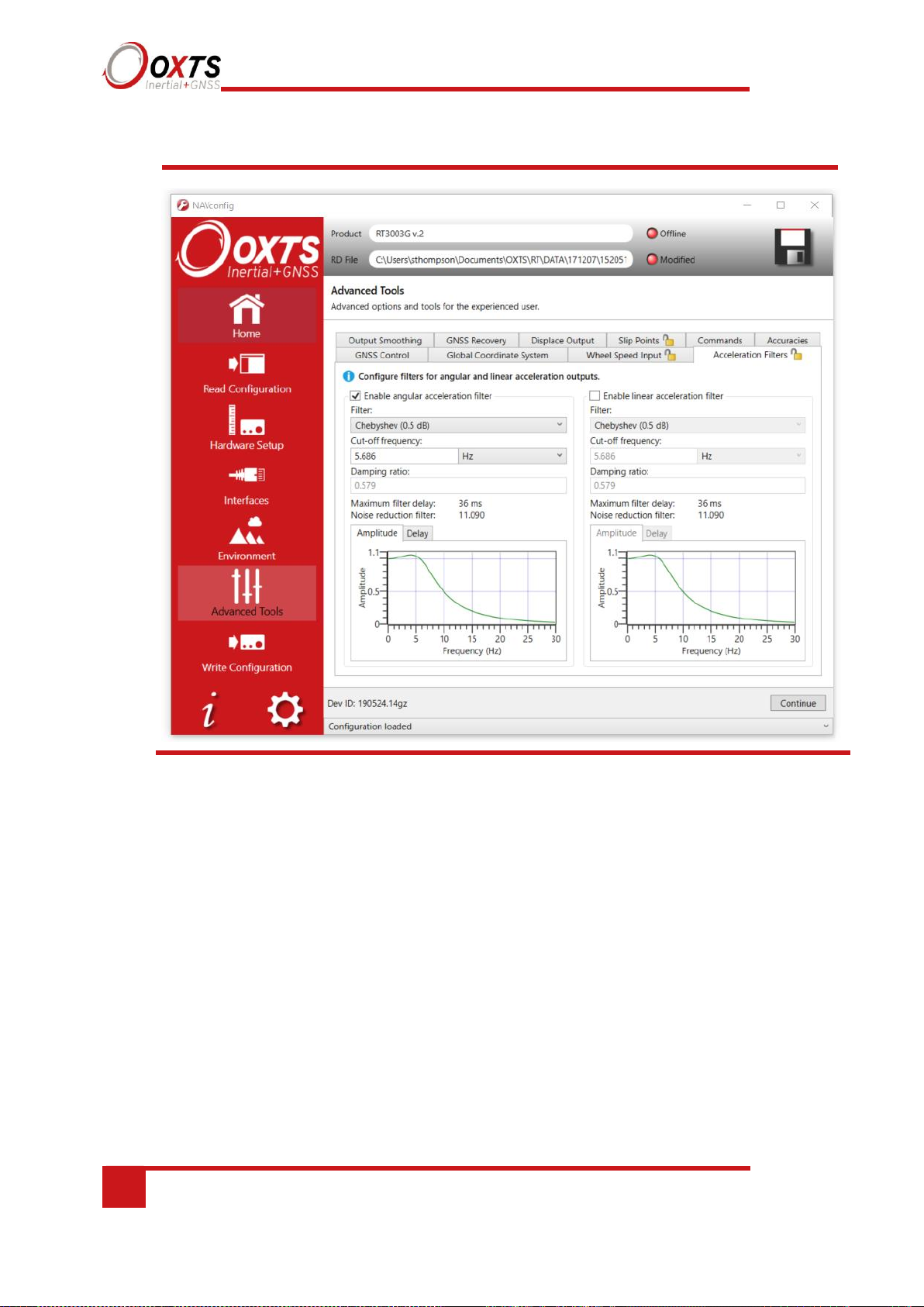
76
Oxford Technical Solutions
Figure 33. NAVconfig Acceleration Filters tab in the Advanced Tools section
Wheel Speed Input
The RT can be factory configured to include a wheel speed input. This reduces the drift in
outputs when GNSS is not available. It is essential to use the Lateral and Vertical No-slip
slip features at the same time as wheel speed corrections.
As with the Lateral No-slip feature, the wheel speed input can only be used on land
vehicles; aircraft and marine vehicles cannot use this option. The wheel speed must not be
used on a steered wheel, it must be used on a wheel that is measuring the forward direction
of the vehicle.
Figure 34 shows the wheel speed configuration window. To enable the wheel speed input,
ensure the checkbox is checked. If this option is disabled, the RT will ignore corrections
from the wheel speed even if it is connected.
Page 77

RT User Manual
Revision: 190902
77
Figure 34. NAVconfig Wheel Speed Input tab in the Advanced Tools section
The distances from the measurement point on the RT to the measurement point of the
wheel speed encoder in the vehicle coordinate frame should be input. The directions can
be selected from the dropdown lists. If the wheel speed is from a prop shaft then the
distance should be measured half way between the two wheels. The illustrations in the
image will change depending on the settings you choose, to help visualise the position of
the RT in relation the wheel speed sensor.
Measurements by default are made to an accuracy of 10 cm. Using higher precision for
the measurement does not improve the results. Using an accuracy figure worse than 20
cm will increase the drift of the RT. The accuracy can be specified exactly in the
Accuracies tab in the Advanced Tools section along with other measurements such as
antenna position.
Page 78

78
Oxford Technical Solutions
Enter the pulses per metre of the wheel speed. A value that is accurate to 10% is
sufficient unless you know the figure more accurately. The RT will improve this
scaling factor itself when GNSS is available. The Improve Configuration utility
can be used to apply a more accurate value calculated by the RT from a calibration
run. If this option is used then the RT should be allowed to recalibrate the scaling
value occasionally to account for tyre wear.
The wheel speed corrections will not be as effective in reducing the drift of the RT if
the wheel speed is measuring two wheels (i.e. after a differential), since the actual
position of the wheel is required for accurate navigation. If a post-differential encoder
must be used then the accuracy cannot be guaranteed.
For best results, a front wheel drive vehicle should be used with the wheel speed on a
rear wheel. The wheel speed pulses from driven wheels are less accurate.
Output smoothing tab
When the Kalman filter in the RT determines that there is some error to correct, this error
is applied smoothly rather than as a jump. The output smoothing controls how fast the
correction is applied to the outputs. This option is particularly useful for autonomous
vehicles or path-following robots as a rapid change in position can lead to a large change
in the steering angle.
Figure 36 shows the Output smoothing tab in the Advanced Tools section within
NAVconfig. Click the checkbox to enable output smoothing and unlock the properties for
editing.
Page 79
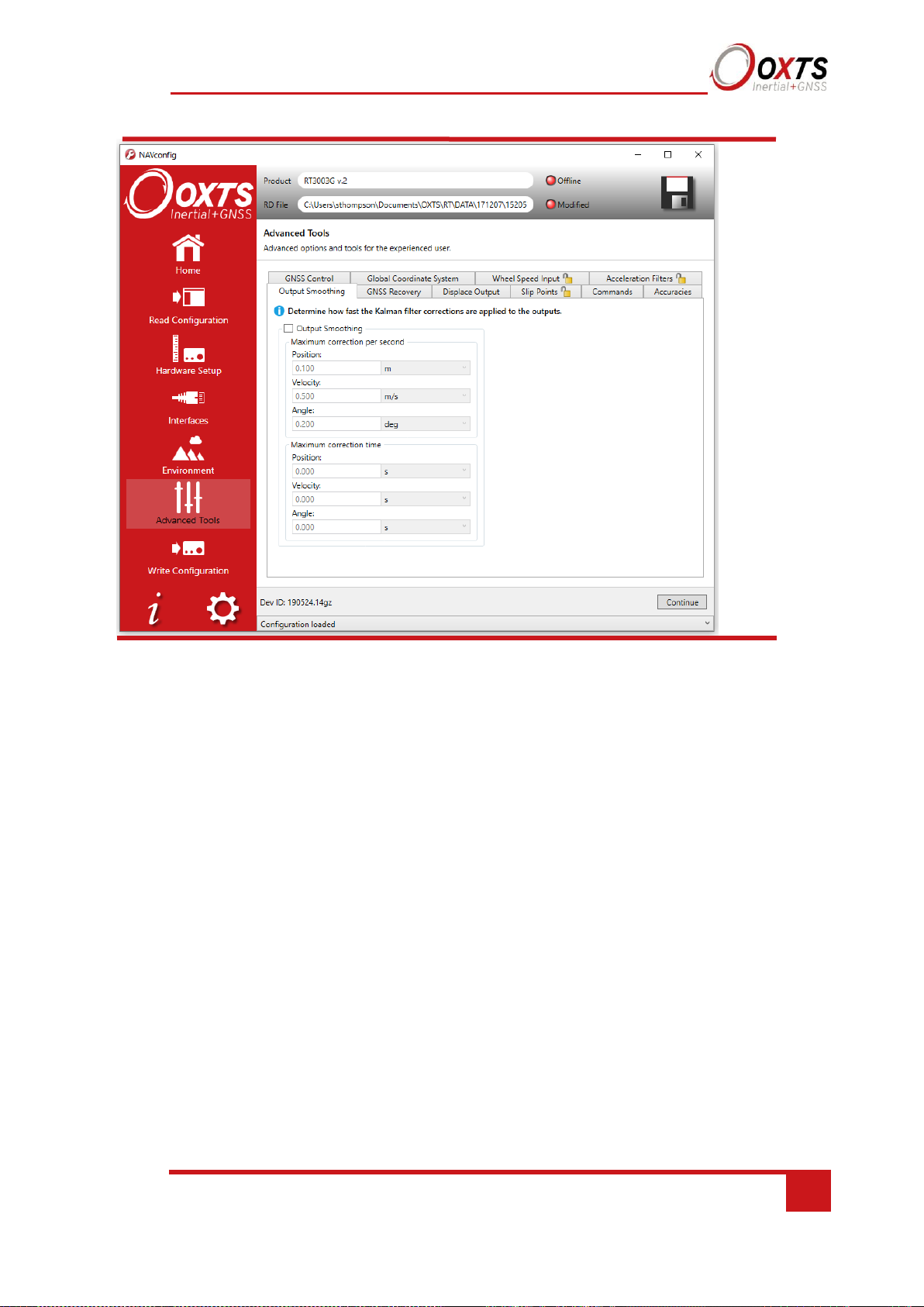
RT User Manual
Revision: 190902
79
Figure 35. NAVconfig output smoothing properties window
The smoothing of the position, velocity and orientation corrections can be controlled
independently. Enter the maximum correction that can be applied every second. For
example, if 0.1 m is entered for the position smoothing then the RT will only correct a
position error by a maximum rate of 0.1 m/s.
If a large error is accumulated (for example, if GNSS is not available for a long period of
time) then it may take a very long time to apply the correction. Under these circumstances
it may be preferable to “jump” the measurement to the correct value quickly. By specifying
a time in the Time limit section for the correction, the RT will jump the measurement if it
will take too long to correct.
Care should be taken not to make the smoothing too small. If these parameters are
inappropriate, then the RT will not be able to make suitable corrections to the outputs and
it will not work correctly.
Note: this function is designed to improve the data in real time. When post-processing the
data using the forwards-backwards combined option, output smoothing should not be used
as it may give unexpected results.
Slip Points tab
The RT can output the slip angle measurements at additional points (maximum of eight
points) on the CAN bus; see Table 38 for the CAN message ID of the slip points. Figure
37 shows the tab for slip point configuration in the Advanced Tools section within
NAVconfig.
Page 80

80
Oxford Technical Solutions
In the Advanced Tools section within NAVconfig, you can select the number of Slip
Points from the Slip Points tab. Select the number of Slip Points you wish to set up and
enter the distances and directions from the RT to the Slip Point.
If you have Output displacement enabled, then the measurements are still from the RT
and not from the output displacement point.
Figure 36. NAVconfig Slip Points tab
Page 81
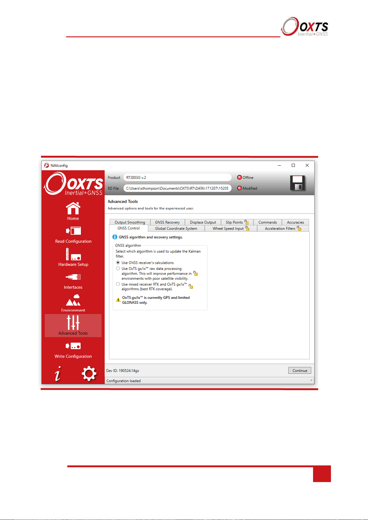
Revision: 190902
81
RT User Manual
GNSS control tab
The GNSS control tab contains advanced options that control how the GNSS information
is managed in the RT. The GNSS Algorithm tab can be used to select the algorithm used
for merging the GNSS and the inertial data in the Kalman filter. The Recovery tab can
be used to decide how to begin using GNSS measurements if they have been rejected or
ignored for a period of time.
Figure 38 shows both tabs in the GNSS control properties window.
Figure 37. NAVconfig GNSS Control tab in Advanced Tools within NAVconfig
Page 82

82
Oxford Technical Solutions
The GNSS Control tab gives a choice of two algorithms for computing the GNSS
measurements. The default option is to use the algorithm provided by the GNSS receiver.
Using this algorithm, the RT will accept position and velocity from the GNSS and use it
to update the Kalman filter.
The gx/ix™ raw data processing algorithm uses the raw data from the GNSS and custom
algorithms to compute position and velocity tailored to the needs of the Kalman filter. It
also improves performance in poor GNSS environments using single satellite aiding
technology and tightly coupled GNSS and inertial measurements. Gx/ix™ mode is
recommended to achieve the highest accuracy in environments where RTK lock may be
difficult to maintain. There is also a third option to use a mix of the two algorithms in
order to gain the benefit from each mode in real time.
Note: gx/ix™ processing is a new technology and is still being developed and improved.
As such there are some limitations to its compatibility. Table 24 details the current
compatibilities of gx/ix™ mode.
Page 83

Revision: 190902
83
RT User Manual
Table 24. gx/ix™ compatibility
GNSS mode
Real-time
Post-process
GPS SPS
GPS DGPS
SBAS
x x RTK
x
GLONASS SPS & DGPS
GLONASS RTK
Note: only RTCM V3 format differential corrections are supported in gx/ix™ mode.
GNSS Recovery tab
The GNSS Recovery tab controls how the RT will accept or reject GNSS measurements.
The RT will automatically reject GNSS updates that it believes are not correct. However,
there is a limit on the number of GNSS measurements the RT will reject. Once this limit
has passed the RT will accept the GNSS update since it is possible the GNSS is correct
and the inertial measurements are not. The GNSS control determines how long the RT
should wait before forcing the GNSS to be accepted. Both the velocity and the position
can be controlled separately.
In the default state the RT will reject up to 20 GNSS measurements before it forces the
GNSS to be accepted. However, in high multipath environments, and when wheel speed
is used, it may be desirable to reject more GNSS measurements. Select the ‘Start
believing measurements after’ option and enter the number of GNSS measurements to
reject before the system starts believing it again.
The RT families have different GNSS receivers which have different update rates for
position and velocity. Table 29 shows the update rates of the RTs.
Table 25. GNSS update rates
Product family
Position
Velocity
RT3000
2 Hz
10 Hz
RT500
2 Hz
10 Hz
This means for example, that if you wish an RT3000 to start believing both position and
velocity GNSS measurements after 30 s, the device it should be configured to start
believing measurements after 60 position updates and 300 velocity updates.
Page 84
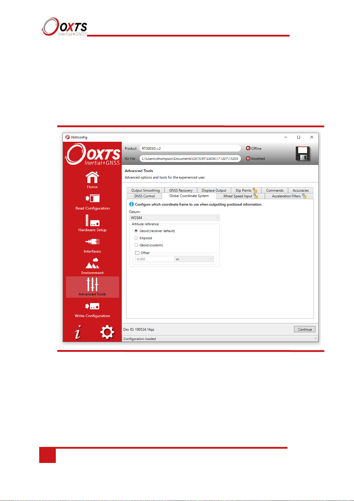
84
Oxford Technical Solutions
Global Coordinate System tab
The RT can output position relative to different coordinate frames. You can change the
coordinate frame settings in the Global Coordinate System tab within Advanced Tools
in NAVconfig, shown in Figure 39.
Figure 38. NAVconfig Global Coordinate System properties window
Page 85

Revision: 190902
85
RT User Manual
From the Global Coordinate System tab you can choose which reference datum to output
latitude and longitude relative to. The default system and the standard for GPS is the
WGS 84 datum.
Note: Currently outputs will only reference datums other than WGS 84 in postprocessing. Real-time outputs will still be referenced to WGS 84 even if another option
is selected.
The Altitude reference can be compared to either ellipsoidal or geoidal height. If
Ellipsoid is selected, the altitude will be output with respect to the reference ellipsoid
selected in the coordinate datum section. If Geoid (receiver default) is selected, the
altitude will be relative to the geoid used in the GNSS receivers. A Custom geoid file
can be used for local variations. To download supported geoid files, go to
http://support.oxts.com/local-geoid-files. The UGF file must be saved in
C:\Users\username\Documents\OXTS\Shared\Custom geoid files. Once the file is
downloaded and saved in this location, it can be selected from the dropdown box.
A constant offset to the specified altitude reference can be applied by checking the Set
offset box typing in a value into the cell.
Accuracies tab
The NAVconfig software uses default accuracies for the measurements made during setup.
These include antenna positions, IMU orientation values and measurements for Advanced
Slip settings. It is recommended that you stick to these default measurements. However, if
you wish to apply specific and more accurate values for measurements then these can be
edited in this Accuracies tab. Enter the values directly into the values field.
Commands tab
Using the Commands tab you can enter device-specific commands that apply specific
features or perform actions onto the RT. The OxTS technical support team often use these
and can provide you with a list of useful commands if you request them at
support@oxts.com.
Page 86

86
Oxford Technical Solutions
The Write Configuration section of NAVconfig
Changes to the RT settings must be sent using Ethernet or Wi-Fi. It is necessary to
configure your computer’s LAN and WLAN settings, so it is on the same network as the
RT.
Figure 39 shows the Write Configuration page.
Figure 39. NAVconfig Write Configuration page
Enter the IP address of the RT you want to configure or select it from the dropdown list.
The dropdown box will list all systems currently connected to the computer’s network so
ensure to select the correct system if there are multiple listed.
Choose whether to commit the configuration changes immediately to the unit or save them
until the next time the unit is reset or power cycled.
Page 87

Revision: 190902
87
RT User Manual
Setting up the base station
For correct operation of the higher accuracy systems it is necessary to use a base station
GNSS receiver. All of the systems can be successfully used without a base station,
however, the specification will only be met if a base station is used.
The base station is a separate GNSS receiver that monitors signals from the GNSS
satellites. Using its knowledge of position it works out the errors in each satellite’s signal.
It also measures the carrier-phase of the signal for kinematic corrections. The carrier-phase
observations and the satellite signal errors are sent from the base station GNSS to the RT
via a radio modem (not provided).
The position of the base station GNSS antenna can either be determined by the base station
GNSS receiver or can be surveyed in by a chartered surveyor. If the base station GNSS
receiver determines its own position, through position averaging, then any error in the base
station receiver will also result in error at the RT. In order to relate the RT signals to maps,
or other items on the world, it is necessary to have a surveyor measure the position of the
GNSS antenna and then tell the base station GNSS receiver what position to use.
For many applications it is not necessary to survey in the base station antenna since an
absolute world-reference is not required. Instead, a local grid can be used.
Using the RT-Base S
The RT-Base S is a self-contained GNSS, radio modem and battery housed in an IP65rated case. For instructions on how to use the RT-Base S see the “RT-Base S User Guide”.
The RT-Base S is supplied with a radio modem. This should be connected to the radio
connector of the RT user cable supplied. This cable supplies power to the radio modem as
well as sending the differential corrections to the RT.
Page 88

88
Oxford Technical Solutions
Initialisation process
Before the RT can start to output all the navigation measurements, it needs to initialise
itself. In order to initialise, the RT needs all the measurements listed in Table 26.
Table 26. Quantities required for initialisation
Quantity
Description
Time
Measured by internal GNSS.
Position
Measured by internal GNSS.
Velocity
Measured by internal GNSS.
Heading
Approximated to course over ground (with large error) when the vehicle moves. Dual
antenna models have the option for static initialisation which does not require any
movement.
Roll, pitch
Vehicle Level option: assumed zero with a large error.
Otherwise: estimated over first 40 s of motion with large error.
The system will start when it has estimates of all of these quantities. Course over ground
will be used as the initial heading when the system exceeds the value set as the
initialisation speed (default of 5 m/s), unless static initialisation has been selected. If the
system is mounted level in the vehicle, then the Vehicle Level option will enable the
system to start immediately. Otherwise the system takes about 40 s to find approximate
values for roll and pitch.
For the initialisation process to work correctly, the RT requires the user to tell it which
way it is mounted in the vehicle, otherwise the course over ground will not be close
enough to the heading.
Real-time outputs
During the initialisation process the system runs 1 s behind, allowing GNSS information
to be compared to information from the inertial sensors. After initialisation the system
has to catch-up from this 1 s lag. It takes 10 s to do this. During the first 10 s the system
cannot output data in real time, the delay decays to the specified latency linearly over this
10 s period.
The system turns the SDNav LED orange to show the outputs are not real-time. When the
system is running in real time this LED is green.
Page 89

Revision: 190902
89
RT User Manual
Warm-up period
During the first 15 minutes of operation the system will not conform to specification.
During this period the Kalman Filter runs a more relaxed model for the sensors. By running
a more relaxed model the system is able to:
• Make better estimates of the errors in the long term (if it does not get these correct then
they become more difficult to correct as time goes on).
• Track the errors in the inertial sensor during their warm-up period (when their errors
change more quickly than normal).
During this period it is necessary to drive the vehicle or the errors will not be estimated and
the specification will not be reached. The NCOM output message (and CAN outputs)
includes status information that can be used to identify when the required specification has
been met. These are plotted in the example below.
The warm-up period is a concern to some customers but it is often very simple to overcome.
Below is an example of a good warm-up procedure that did not involve a lot of work for
the user. In this example the key features are:
• The RT was configured well – the GNSS antenna position, Advanced slip options and
dual-antenna separation were measured accurately in advance.
• The RT was turned on as soon as possible. In this case it took us 15 minutes to get all
the other equipment sorted out. The RT was stationary for most of this period – which
is not a problem.
• Although in this example the RT was receiving corrections from a base station while
stationary, it is not necessary. The base station should be working before the dynamic
driving starts so the RT can use the best information to self-calibrate (if a base station is
not being use this does not apply).
• There are 6 minutes during which the car was driven in figures of eight. From the graphs
you can see the RT3003 is accurate almost after the first figure of eight; after that the
improvement is very small.
The trick is to turn the RT on early; do not reconfigure it (which resets it) or cycle the
power.
Figure 41 shows the route driven and Figure 42 shows the accuracy estimated by the
Kalman filter for various output parameters during the first 25 minutes. The quality of
initialisation would have been the same if the stationary period was 10 minutes, followed
by 5 minutes of driving. The time on the graphs is the time from initialisation. In this
example the RT3003 was initialised 25 s after starting up; the quality of initialisation would
be the same if it had been not been initialised for the first 10 minutes, then initialised and
driven for 5 minutes.
Page 90

90
Oxford Technical Solutions
Figure 40. Example warm-up driving route
At the start there is just a small amount of motion to get the RT3000 initialised. During this
time the Kalman filter cannot improve the position accuracy because the position of the
GNSS antenna is not known accurately and cannot be estimated without motion. The
accuracy of the velocity, roll and pitch steadily improves as the Kalman filter places more
and more weight on the inertial sensors. At this point the heading accuracy is worse than
the scale of the graph ((d) in Figure 41); the heading is not accurate and the dual antenna
system cannot measure the angle of the GNSS antennas compared to the inertial sensors,
so the dual antenna cannot provide accurate information.
Just after 500 s the RT3000 is driven (it is the small loop on the east side in Figure 40, not
the figures of eight). This small amount of driving is sufficient for the Kalman filter to gain
confidence in the antenna position and to improve the alignment of the two GNSS antennas
compared to the inertial sensors. After this period the position accuracy is better than 1 cm
and the heading is better than 0.2°.
Page 91

Revision: 190902
91
RT User Manual
Figure 41. Example warm-up accuracy estimates
(a) Forward velocity. (b) Position accuracies. (c) Velocity accuracies. (d) Orientation accuracies.
Page 92

92
Oxford Technical Solutions
You can see the RT is nearly at specification after just this small amount of driving.
However, experience tells us the Kalman filter will continue to make some improvements
(not obvious) during the first few figures of eight. The main part of the motion occurs
after 1100 s when the car was driven in a figure of eight for 6 minutes.
These are fairly large figures of eight driven at relatively low speeds. Notice the brake
stops in the velocity graph ((a) in Figure 41) where the speed falls to zero. These are
important parts of the warm-up – so as many states in the Kalman filter as possible can
be updated.
Notice how close to the specification the RT is even without the figure of eight
manoeuvres. A proper warm-up is recommended in order to achieve the highest level of
accuracy. However the effect is small and only significant when you need the full
performance of the RT.
Improving the configuration after a warm-up
Committing the configuration to the RT
After the warm-up process has been completed you can commit the improved settings to
the RT using NAVconfig. The RT takes its improved orientation, antenna positions and
wheel speed sensor position from values generated in real time during the warm-up and
uses them to improve accuracies.
To commit improved settings to the RT, first open NAVconfig and select ‘Improve
configuration’. Figure 43 shows this option on the NAVconfig home section.
Page 93

Revision: 190902
93
RT User Manual
Figure 42. NAVconfig Home section
Read configuration section in NAVconfig improved configuration wizard
If you are connected to a device via Wi-Fi or Ethernet, then select “Read settings from a
device” and choose the device from the available list. If the file has been logged to the PC
already then you can choose ‘Read settings from a data (RD) file’ or ‘Read settings from
a folder’ by locating the file or folder on your PC.
Page 94

94
Oxford Technical Solutions
Figure 43. NAVconfig Read Configuration
Click ‘Next’ to continue.
Confirm whether the improved data should be read from: The Device, or a File. Click
‘Next’ to continue.
Page 95

Revision: 190902
95
RT User Manual
Figure 44. NAVconfig Improve configuration data source
The Select Settings screen will appear. From the list displayed, select the settings that you
wish to view. These will be determined according to what is enabled on your device.
Page 96

96
Oxford Technical Solutions
Figure 45. NAVconfig Improve configuration Select Settings
Select the settings that you wish to improve in the configuration from the options available. By
clicking the down arrows, you can expand the settings and view the values that have been
improved after the warm-up. It is recommended that you review these before clicking ‘Next’ to
continue.
The final stage of the improved settings wizard is to write the configuration to the device and
apply the improved settings with new accuracies. You can choose whether to commit the
improved settings to the device after a rest or power cycle (recommended) or to apply them
immediately (which does not get saved into the configuration file on the device). For the
improved settings to apply to the device in the case where the device will remain in the car for
some time, it is recommended that you apply the improved settings and reset the device.
Page 97
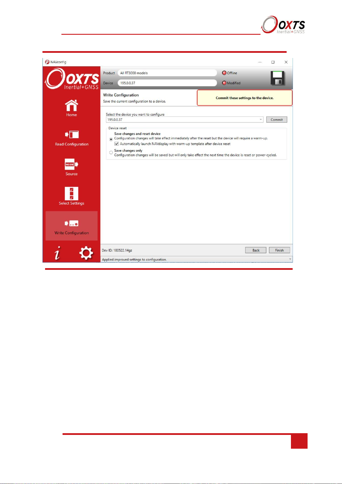
Revision: 190902
97
RT User Manual
Figure 46. NAVconfig Improve Configuration Write Configuration
Before you write the improved settings to the device, choose whether you want to apply
the settings immediately or after a power cycle.
Post-processing data
Data stored on the RT is in a raw, unprocessed format; these files have an RD extension.
The advantage of this is it can be reprocessed with different configuration settings. For
example, if the configuration was configured incorrectly when running in real time, then
the configuration can be changed and the data can be reprocessed post-mission.
The software suite provided with the RT includes the NAVsolve software which can be
used to reprocess the data. The NAVsolve Wizard also gives the user the ability to change
the NCOM binary output format to text.
A full explanation of NAVsolve is given in the “NAVsolve manual”, which can be
downloaded from the OxTS support website.
Page 98

98
Oxford Technical Solutions
Laboratory testing
There are several checks that can be performed in the laboratory to ensure the system is
working correctly. The most fragile items in the system are the accelerometers, the other
items are not subject to shock and do not need to be tested as thoroughly.
Accelerometer test procedure
To check the accelerometers are working correctly, follow this procedure.
1. Connect power and a laptop to the system.
2. Commit a default setting to the RT using NAVconfig, then run NAVdisplay.
3. Click the ‘Calibration’ button, then select the ‘Navigation’ tab and ensure the x, y, and
z accelerations (values 19 to 21) are within specification when the RT is placed on a
level surface in the orientations according to Table 31.
Table 27. Acceleration measurement specifications
Orientation Acceleration measurement
x y z
Flat
Flat
Down
z-acceleration between –9.7 and –9.9 m/s
2
Flat
Flat
Up
z-acceleration between 9.7 and 9.9 m/s
2
Down
Flat
Flat
x-acceleration between –9.7 and –9.9 m/s
2
Up
Flat
Flat
x-acceleration between 9.7 and 9.9 m/s
2
Flat
Down
Flat
y-acceleration between –9.7 and –9.9 m/s
2
Flat
Up
Flat
y-acceleration between 9.7 and 9.9 m/s
2
This test is sufficient to ensure the accelerometers have not been damaged.
Gyro test procedure
To check that the gyros (angular rate sensors) are working correctly, follow
this procedure:
Page 99

Revision: 190902
99
RT User Manual
1. Connect power and a laptop to the system.
2. Commit a default setting to the RT using NAVconfig, then run NAVdisplay.
3. Click the ‘Calibration’ button, then select the ‘Navigation’ tab and scroll to view
the x, y, and z angular rates (values 30 to 32).
4. Rotate the RT according to Table 32 and check the angular rate measurements
occur.
5. With the unit stationary, check all the angular rates are within ±5°/s. (In general
they will be within ±0.5°/s, but the algorithm in the RT will work to specification
with biases up to ±5°/s.)
Table 28. Angular rate measurement specifications
+ve Zero Zero The x-axis should indicate positive rotation, others are
small.
Zero +ve Zero The y-axis should indicate positive rotation, others are
small.
Zero Zero +ve The z-axis should indicate positive rotation, others are
small.
It is hard to do a more exhaustive test using the angular rate sensors without specialised
software and equipment. For further calibration testing it is necessary to return the unit
to OxTS.
Note that the RT is capable of correcting the error in the angular rate sensors very
accurately. It is not necessary to have very small values for the angular rates when
stationary since they will be estimated during the initialisation process and warm-up
period. This estimation process allows the RT to go for long periods without requiring
recalibration.
z
Angular rate
Orientatio
n y
x
The x-axis should indicate negative rotation, others
are small.
Zero
Zero
–ve
The y-axis should indicate negative rotation, others
are small.
Zero
–ve
Zero
The z-axis should indicate negative rotation, others
are small.
–ve
Zero
Zer
Page 100

100
Oxford Technical Solutions
Testing the internal GNSS and other circuitry
To check all the internal circuits in the RT are working correctly and the
navigation computer has booted correctly, use the following procedure:
1. Connect power to the system, connect the system to a laptop computer and
run the visual display software (NAVdisplay).
2. Use Table 33, below, to check the status fields are changing.
Table 29. Status field checks
IMU packets 100 per second or 250 per second, depending on product model.
GPS packets Between 2 and 20 per second (depending on system).
GPS2 packets
1
Between 2 and 20 per second (depending on system).
1
The GPS2 related fields will only increase for dual antenna systems.
These checks will ensure the signals from the GNSS and from the inertial sensors are
being correctly received at the navigation computer.
Field Increment rate
GPS chars skipped Not changing (but not necessarily zero).
IMU chars skipped Not changing (but not necessarily zero).
GPS2 char skipped
1
Not changing (but not necessarily zero).
 Loading...