


™
SPOT-1
INFRARED EMITTER PANEL
Installation
&
Operation
Manual

TABLE OF CONTENTS
SPOT-1 INTRODUCTION ................................................................................................................. 1
SPOT-1 CALLOUTS - INTERNAL POWER SUPPLY ............................................................................. 2
SPOT-1 CALLOUTS - EXTERNAL POWER SUPPLY ............................................................................. 3
SPOT-1 EMITTER SET-UP ................................................................................................................ 4
SPOT-1 CONNECTIONS .................................................................................................................. 5
SPOT-1 DIMENSIONAL SPECIFICATIONS ........................................................................................ 6
SPOT-1 USER INSTALLATION NOTES .............................................................................................. 7
SPOT-1 USER INSTALLATION NOTES (CONTINUED) ........................................................................ 8
SPOT-1 SPECIFICATIONS ............................................................................................................... 9
OXMOOR FACTORY SERVICE ......................................................................................................... 10
OXMOOR TWO YEAR LIMITED WARRANTY ..................................................................................... 10
CONTACT OXMOOR ....................................................................................................................... 10

SPOT-1 INTRODUCTION
• Discreet, unobtrusive H7TCP style recessed enclosure
• Fully gasketed junction box
• Fully adjustable hanger for 24” joists
• Plenum Approved flexible metallic tubing and connectors
• 72- diode array for “spot” coverage
• IR bandwidth from 95 kHz through 3 mHz
• Energy saving feature when operating at 95 kHz and 250 kHz
• UL and Plenum listed
Oxmoor Corporation, LLC’s SPOT-1 Infrared Emitter Panel simplifies the design requirements for Infrared transmission in small facilities. This Infrared Emitter Panel is ideal for applications where
discreet, unobtrusive IR systems are required.
The 72-diode array is designed to cover small “spot”
areas of approximately 314 to 2,800 square feet. It
is ideal for use in hotels, courtrooms, classrooms,
museums, and other facilities of this type.
SPOT-1 is housed in a standard Halo H7TH 6-inch
recessed ceiling light enclosure. The enclosure
comes with the Halo 70PSH trim ring and lens and
provides for easy installation in most types of overhead ceiling.
SPOT-1 has an IR transmission bandwidth from
95 kHz through 3 MHz. It requires a single AC
power connection between 100 VAC and 230 VAC,
and a modulated RF connection made through a
BNC style connector. With an input impedance of
25 k ohms at 95 kHz, multiple units can be series
and driven from a single modular channel.
SPOT-1 provides an automatic on and off feature.
When using either a 95 kHz or 250 kHz carrier
frequency (the standard frequencies used for hearing impaired applications) an internal jumper can
be set to detect the 95 kHz or 250 kHz kHz carrier
frequency. The unit turns itself off when the carrier
frequency is not present. This feature greatly
extends the life of the emitter panels.
SPOT-1 can be used with any standard IR Receiver
that operates between 95 kHz and 3 MHz.
The Emitter Panel is ideal in applications where
adjacent rooms open into one large room, as in a
room combining application. The panels can be
synchronized by using the Oxmoor PIR-88M EightChannel Programmable Infrared Modulator.
For more information on any Oxmoor product, please contact
the Oxmoor Sales Department. Or download complete product brochures and manuals at our website: www.oxmoor.com.
Page 1
SPOT-1i CALLOUTS - INTERNAL POWER SUPPLY
1. HOUSING – Die-stamped, 20 gauge, cold rolled steel
with white powder coat finish.
2. RF CONDUIT KNOCKOUT – 1/2” uniform opening for RF
cable entry. NOTE: requires a gasketed EMT air tight compression connector or gland nut when used in a plenum
ceiling.
3. PLASTER FRAME – Housing adjusts in plaster frame
1-3/8” to accommodate different ceiling thicknesses.
4. BAR HANGERS – Fully adjustable “nail-less” bar hangers fit between 24” joists and span 24” T-bars. Hanger bars
are scored for reducing for 12” joist spans. Housing may
be positioned at any point along length of fully extended
bar hangers.
5. TRIM RING – White metal trim ring with glass lens.
6. BRACKET PLATE – Ridge plate adjusts and locks with-
out tools. Used to support the internal power supply on
the SPOT-1i PS version.
7. RF INPUT CONNECTOR – BNC-style RF input connector. Input impedance 25 k ohms at 95 kHz.
8. DC POWER SUPPLY – 24V DC supply at 1.25 amps, volt-
age regulation ± 5 % with a maximum ripple P-P of 240
mV. Accepts 100 - 230V AC connection through junction
box.
9. DC POWER CONNECTION – 3-pin header connector. Center Pin Positive with both outside pins negative.
10. DIODE ARRAY – 72-diode array designed to cover small
“spot” areas of approximately 314 to 2,800 square feet.
11. JUNCTION BOX – Fully gasketed for Plenum listing. UL
listed for through branch circuit wiring.
12.POWER KNOCKOUTS – Positioned to accommodate
straight conduit runs. All conduit knockouts are uniform
1/2” size with pry out slots.
13.CONDUIT FITTINGS – Plenum-approved flexible metallic tubing and gasketed connectors.
13
1
2
4
5
3
7
6
12
8
11
9
10
Figure 1.0: SPOT-1i Infrared Emitter With Internal Power Supply
Page 2

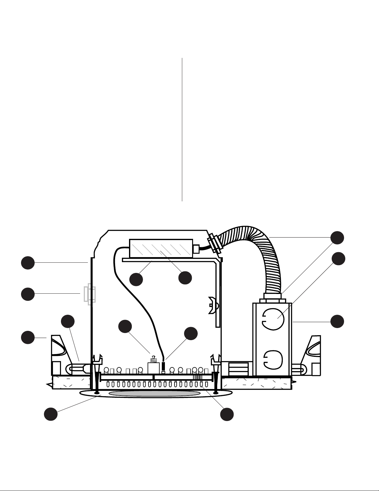
SPOT-1 CALLOUTS - EXTERNAL POWER SUPPLY
1. HOUSING – Die-stamped, 20 gauge, cold rolled steel with
white powder coat finish.
2. RF CONDUIT KNOCKOUT – 1/2” uniform opening for RF
cable entry. NOTE: Requires a gasketed EMT air tight compression connector or gland nut when used in a plenum
ceiling.
3. PLASTER FRAME – Housing adjusts in plaster frame
1-3/8” to accommodate different ceiling thicknesses.
4. BAR HANGERS – Fully adjustable “nail-less” bar hangers fit between 24” joists and span 24” T-bars. Hanger bars
are scored for reducing for 12” joist spans. Housing may
be positioned at any point along length of fully extended
bar hangers.
5. TRIM RING – White metal trim ring with glass lens.
6. RF INPUT CONNECTOR – BNC-style RF input connector.
Input impedance 25 k ohms at 95 kHz.
7. DC POWER CONNECTION – 3-pin header connector. Center Pin Positive with both outside pins negative. NOTE:
Requires 24V DC supply at 1.25 amps, voltage regulation
± 5 % with a maximum peak to peak ripple of 240 mV.
8. DC POWER CABLE – 2-conductor cable, terminates in
junction box.
9. DIODE ARRAY – 72-diode array designed to cover small
“spot” areas of approximately 314 to 2,800 square feet.
10. JUNCTION BOX – Fully gasketed for Plenum listing. UL
listed for through branch circuit wiring.
11.POWER KNOCKOUTS – Positioned to accommodate
straight conduit runs. All conduit knockouts are uniform
1/2” size with pry out slots.
12.CONDUIT FITTINGS – Plenum approved flexible metallic tubing and gasketed connectors.
12
1
2
4
5
3
6
11
8
10
7
9
Figure 1.1: SPOT-1e Infrared Emitter With External Power Supply
Page 3

SPOT-1 EMITTER SET-UP
SPOT-1 SET-UP OVERVIEW
When driving SPOT-1 with a carrier frequency operating
at 76.8 kHz, 95 kHz, or 250 kHz, SPOT-1 can be configured
to automatically turn off when no carrier frequency is
detected. SPOT-1 will turn on again when it detects the
appropriate carrier frequency. This feature conserves
energy and extends the life of the 72 emitter diodes.
If the transmitter is operating at a carrier frequency other
than 76.8 kHz, 95 kHz, or 250 kHz, jumper P5 has to be
set to the OFF position. This causes SPOT-1 to remain on
until its power is removed. If P5 is set to the OFF position,
jumpers P6 and P7 are removed from the circuit and can
be left in any position.
FACTORY SETTINGS ARE:
P5 - Carrier Detection On
P6 - 95 kHz Selected
P7 - 250 kHz Selected
SPOT-1 Emitter Driver Board
12-Pin Header Connection
For Emitter Driver Board
RF Jack
F1
1-1/4 Amp Line Fuse
Figure 2.0: Factory Set-Up Jumper Configuration
P5 – ON Selected
P6 – 95 kHz Selected
ONON
OFFOFF
ON
OFF
ONON
OFFOFF
P5
P6 P7
76.8 kHz76.8 kHz
76.8 kHz
95 kHz95 kHz
95 kHz
95 kHz95 kHz
P2
250 kHz250 kHz
250 kHz
250 kHz250 kHz
76.8 kHz76.8 kHz
OffOff
Off
OffOff
P7 – 250 kHz Selected
JUMPER CONFIGURATION
(Refer to Figure 2.0)
Jumper P5
If the RF modulator is operating at 76.8 kHz, 95 kHz, or
250 kHz, move jumper P5 to the ON position. If the RF
modulator is operating at any other frequency, jumper P5
must be in the OFF position.
Jumper P6
If the RF modulator is operating at 76.8 kHz, move jumper
P6 to the 76.8 kHz position and P7 to the OFF position. If
the RF modulator is operating at 95 kHz, move jumper P6
to the 95 kHz position and P7 to the OFF position.
Jumper P7
If the RF modulator is operating at 250 kHz, move jumper
P7 to the 250 kHz position. P6 can be positioned either to
76.8 kHz or 95 kHz when operating at 250 kHz.
CAUTION: If the 250 kHz frequency is not used, be sure
to position the 250 kHz detector in the OFF position!
CARRIER DETECTION CONFIGURATION CHART
Modulation Jumper
Frequency Position
P5P5
P5
P5P5
P6P6
P6
P6P6
P7P7
P7
P7P7
76.8 kHz On 76.8 Off
95 kHz On
250 kHz
On
95
X
Off
250
All Others Off X X
X = Either Position
BOLD & ITALIC
= Factory Settings
USER CONFIGURATION CHART
Modulation Jumper
Frequency Position
76.8 kHz
95 kHz
250 kHz
All Others
P5 P5
P5
P5 P5
P6P6
P6
P6P6
P7 P7
P7
P7 P7
Page 4

SPOT-1 CONNECTIONS
SPOT-1i WITH INTERNAL POWER SUPPLY
(Refer to Figure 3.0)
The internal supply requires 100 - 230V AC at 30 watts
maximum. Connect the AC wiring to SPOT-1 through the
JUNCTION BOX as shown, using 1/2” conduit terminated
into an EMT style steel gasketed connector.
EMT Compression Steel Connector with Gasket
“Provided by Contractor”
1/2” Conduit
Figure 3.0: 100 - 230V AC Connection
100-230V AC
using class
2 wiring
Junction Box
RF CONNECTION FOR IN-LINE SPOT-1
(Refer to Figure 3.2)
A 1/2” cutout is provided for the RF cable entrance and
exit. The cutout can be used with 1/2” conduit terminated
into an EMT compression connector. If using Plenum cable,
termination can be made through a gasketed Gland Nut.
A splitter (T) is provided with each SPOT-1. The splitter
routes RF to the unit and then provides a means to route
the RF to the next inline unit.
EMT Compression, Steel Connector with Gasket
“Provided by Contractor”
RF Cable from
modulator
RF Cable to next SPOT-1
SPOT-1e WITH
(Refer to Figure 3.1)
EXTERNAL
POWER SUPPLY
SPOT-1 Requires 24V DC at 1.25 amps, voltage regulation
± 5 % with a maximum peak to peak ripple of 240 mV.
Connect the external power supply to SPOT-1 through the
JUNCTION BOX as shown: Using 1/2” conduit terminated
into an EMT style steel gasketed connector.
EMT Compression Steel Connector with Gasket
1/2” Conduit
“Provided by Contractor”
24V DC, 1.25A
using class
Junction Box
2 wiring
Te rminate the RF cable with a standard BNC style T Connector
Figure 3.2: RF In Line Connection
RF CONNECTION FOR END OF LINE SPOT-1
(Refer to Figure 3.3)
A 1/2” cutout is provided for the RF cable entrance. The
cutout can be used with 1/2” conduit terminated into an
EMT compression connector. If using Plenum cable, termination can be made through a gasketed gland nut.
RF 50 ohm or 75 ohm terminator.
Determined by transmitter output impedance
EMT Compression,
Steel Connector with Gasket
“Provided by Contractor”
RF Cable from
modulator
Figure 3.1: DC Connection
Terminate the RF cable with a standard BNC style T Connector
Figure 3.3: RF End Of Line Connection
Page 5

SPOT-1 DIMENSIONAL SPECIFICATIONS
RF Cable Entrance
Power Entrance
8"
14" to 24"
Glass Lens
6"
11"
Emitter Board
Metal Trim Ring
5 1/4"
8"
Figure 4.0: Dimensional Specifications
Page 6

SPOT-1 USER INSTALLATION NOTES
Page 7

SPOT-1 USER INSTALLATION NOTES (CONTINUED)
Page 8

SPOT-1 SPECIFICATIONS
INPUT TYPE .................................................................................... RF
INPUT CONNECTOR ........................................................................ BNC
INPUT IMPEDANCE ......................................................................... 25 k ohms at 95 kHz
MAXIMUM CARRIER FREQUENCY .................................................... 3 MHz
MAXIMUM RF INPUT LEVEL WITH 50 OHM LINE TERMINATION ...... 3 V Peak to Peak (13.5 dBm)
NUMBER OF DIODES....................................................................... 72
IR OUTPUT ...................................................................................... 1.5 W / Steradium, On Axis
WAVE LENGTH OF RADIATED INFRARED LIGHT ............................... 880 nm
AUTOMATIC ON/OFF FUNCTION, INTERNAL JUMPER SELECT ........ Carrier Detect for 95 kHz and 250 kHz
STORAGE TEMPERATURE ................................................................ 0°C to 70°C
OPERATING TEMPERATURE ............................................................. 10°C to 50°C
HUMIDITY ....................................................................................... 80% Max., Non-condensing
AC POWER ...................................................................................... 90-264 VAC, 35 Watts, 47 to 63 Hz
PACKAGING ..................................................................................... HALO Recessed 6-in. H7TH Housing
MOUNTING ..................................................................................... Ceiling Mount
DIMENSIONS ................................................................................... 203mm H x 279mm W x 356mm D
(8 in. H x 11 in. W x 14 in. D)
WEIGHT ........................................................................................... 2.4kg (5 lb. 3 oz.)
COVERAGE FOR CEILING INSTALLATION HEIGHT:
Single Channel with a Ceiling Height of ................................... 24 ft.
Optimum Radius 4 ft. from the Floor Surface ......................... 30 ft.
Maximum Radius a 4 ft. from the Floor Surface ...................... 45 ft.
Single Channel with a Ceiling Height of .................................. 12 ft.
Optimum Radius 4 ft. from the Floor Surface ......................... 20 ft.
Maximum Radius a 4 ft. from the Floor Surface ...................... 35 ft.
Single Channel with a Ceiling Height of .................................... 9 ft.
Optimum Radius 4 ft. from the Floor Surface .......................... 16 ft.
Maximum Radius 4 ft. from the Floor Surface ........................ 30 ft.
Single Channel with a Ceiling Height of ................................... 8 ft.
Optimum Radius 4 ft. from the Floor Surface ..........................10 ft.
Maximum Radius 4 ft. from the Floor Surface ........................ 20 ft.
8' Ceilling
Side View Of Typical Ceiling Installation With Ceiling Height of 8 Feet
10' On Center 10' On Center
Receiver 4' Off Floor
Optimum Coverage Area
Figure 5.0: Typical Coverage Pattern
Specifications subject to change without notice.
Page 9

OXMOOR FACTORY SERVICE
For service information contact:
Oxmoor Product Service Department
309 Cahaba Valley Parkway
Birmingham, Alabama 35124
E-mail: info@oxmoor.com
Additional Installation & Operation Manuals are available from Oxmoor. Contact the
Oxmoor Sales Department for pricing and other ordering information. Consult
warranty statement for cautions concerning unauthorized service.
Telephone: (205) 982-8200
Toll Free: 1 (800) 262-6898
Fax: (205) 982-8250
Internet: www.oxmoor.com
OXMOOR TWO YEAR LIMITED WARRANTY
Oxmoor warrants that each Oxmoor electronic product shall be free from defects in workmanship
and materials and will, at its option, repair or replace any part of the product without charge
provided the product is delivered to Oxmoor within two years of date of original purchase from
or delivery by an authorized Oxmoor dealer. Excluded from this warranty are finish and
appearance items and malfunction resulting from abuse, from use that is not in accordance with
instructions, or operation under other than specified conditions. Also excluded are incidental or
consequential damages except where precluded by applicable law. This warranty provides the
customer with specific legal rights; there may also be other rights which vary from state to state.
Repair by other than Oxmoor Factory Service Department or its authorized service agency,
unauthorized modification, or the removal or defacing of the serial number will void this
warranty.
Products returned for factory warranty service must be prepaid and packaged in such a way as to
insure safe transit and must be accompanied by a sales slip or other valid proof of purchase date.
PRIOR AUTHORIZATION FROM OXMOOR IS REQUIRED FOR RETURN. Contact Oxmoor for
a Return Authorization (R.A.) Number and shipping information before returning product for
service.
CONTACT
OXMOOR
Oxmoor Corporation, LLC, 309 Cahaba Valley Parkway, Birmingham, AL 35124 USA
Toll Free 1 (800) 262-6898 Telephone (205) 982-8200 Fax (205) 982-8250 E-mail info@oxmoor.com
For 24-hour access to product specs and information visit Oxmoor's complete product line on the internet at www.oxmoor.com.
Oxmoor is a registered trademark of Oxmoor Corporation, LLC.
Specifications and design are subject to change without notice.
Oxmoor SPOT-1 Infrared Emitter Panel
Rev. 4.5/072601 Part Number:1700017
 Loading...