

Oxmoor RMX-62 Installation Manual
RMX-44™ & RMX-62
MIXING MATRIX
™
Installation
&
Operation
Manual

TABLE OF CONTENTS
RMX-44 & RMX-62 INTRODUCTION ............................................................................................. 1
RMX-44 CALLOUTS ..................................................................................................................... 2
RMX-44 BLOCK DIAGRAM ........................................................................................................... 3
RMX-62 CALLOUTS ..................................................................................................................... 4
RMX-62 BLOCK DIAGRAM ........................................................................................................... 5
RMX-44 & RMX-62 SET-UP ..........................................................................................................6
RMX-44 & RMX-62 SET-UP (CONTINUED) .................................................................................... 7
RMX-44 AUDIO & CONTROL PORT PIN ASSIGNMENTS ................................................................ 8
RMX-62 AUDIO & CONTROL PORT PIN ASSIGNMENTS ................................................................ 9
RMX-44 & RMX-62 APPLICATIONS ............................................................................................. 10
USER INSTALLATION & SET-UP NOTES ....................................................................................... 11
USER INSTALLATION & SET-UP NOTES ....................................................................................... 12
RMX-44 & RMX-62 SPECIFICATIONS .......................................................................................... 13
OXMOOR FACTORY SERVICE ...................................................................................................... 14
OXMOOR TWO YEAR LIMITED WARRANTY .................................................................................. 14
CONTACT OXMOOR .................................................................................................................... 14

RMX-44 & RMX-62 INTRODUCTION
• Front-panel input trimmers with +/- 15 dB gain adjustment
• Logic control port for setting various output configurations,
including a mix of the inputs
• Electronically balanced, XLR-type inputs and outputs
• +24 dBu input signal levels
• +24 dBm output signal levels
• Built-in RF suppression
• UL Listed
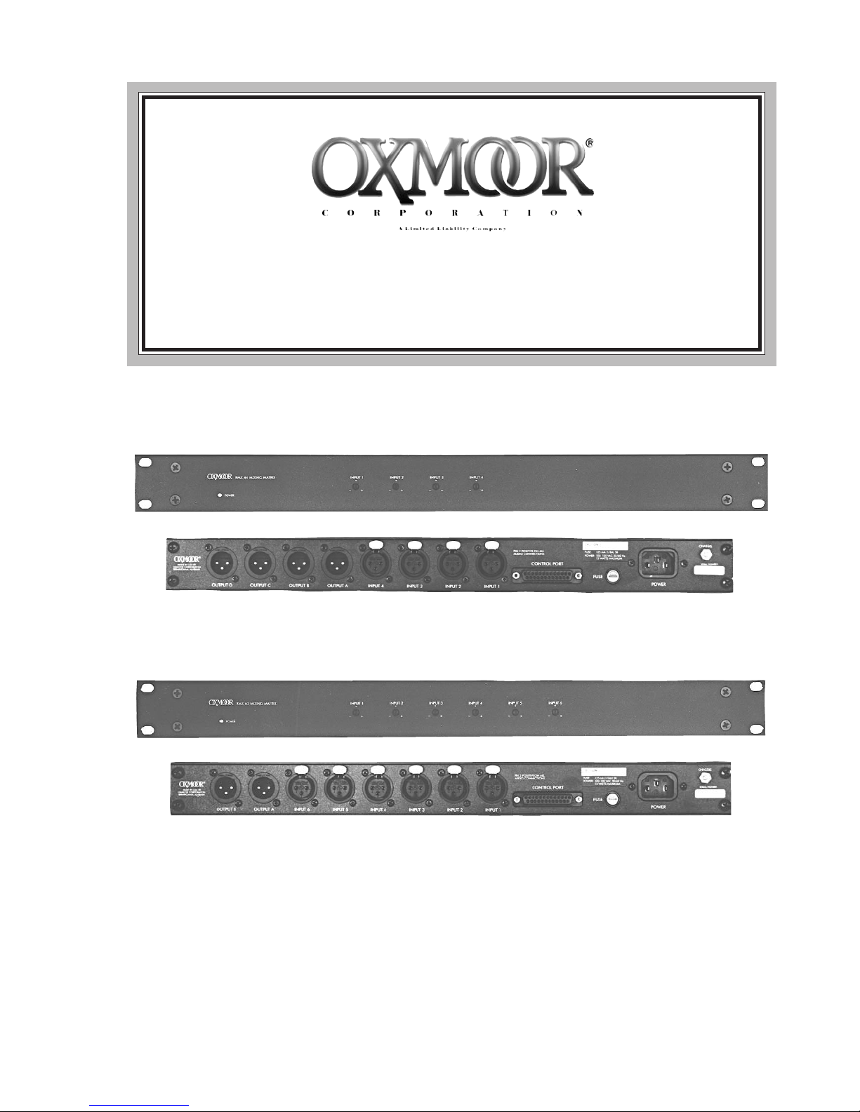
The RMX-44 and RMX-62 Mixing Matrixes may
be used as buffer/mixer/distribution amplifiers.
The RMX-44 offers a four-in by four-out configuration while the RMX-62 is a six-in by two-out
system. Each compact unit is housed in a 1U,
rackmount chassis and weighs just under 8.5
pounds.
The RMX-44 and RMX-62 are intended for use in
sound reinforcement, permanent installations,
playback, and other audio systems requiring
high-quality operation with flexible audio routing from remote locations.
The RMX-44 unit allows, for example, stereo components and their sum to be assigned to separate
output lines. High and low input and output levels can also be freely intermixed without additional hardware, facilitating such common conversion tasks as interfacing hi-fi equipment with
professional audio systems.
The RMX-44 and RMX-62 input stages are electronically balanced and fitted with standard 3-pin,
XLR-type connectors. Front-panel gain trimmers
enable the installer to compensate for various input signal levels. RF suppression circuitry safeguards against radio-frequency interference in
hostile environments.
For enhanced flexibility on both units, each output driver can be set for balanced or unbalanced
operation using internal jumpers. The output
stages will deliver a +24 dBm maximum output
level, with overall 20Hz to 20 kHz frequency response, +0, -0.3 dB.
Both devices are also available with optional output transformers. Designate Model RMX-44T or
Model RMX-62T. Transformer equipped version
may be operated Balanced or Unbalanced without any change to the internal jumpers.
Designed to satisfy exacting professional standards, the RMX-44 and RMX-62 offer excellent
performance in highly dependable packages.
Their impressive audio specifications are ideally
suited to recording and broadcast applications,
yet their rugged chassis and exceptional immunity to environmental stress make them an ideal
choice for demanding road work and commercial installations.
The RMX-44, RMX-44T, RMX-62, and RMX-62T
Mixing Matrixes are Underwriters Laboratories
(UL) Listed.
Page 1

RMX-44 CALLOUTS
1
OXMOOR
POWER
OUTPUT D OUTPUT C
RMX-44 MIXING MATRIX
7
7
OUTPUT B
INPUT 1
OUTPUT A
4
4
INPUT 2 INPUT 3 INPUT 4
INPUT 4 INPUT 3
2
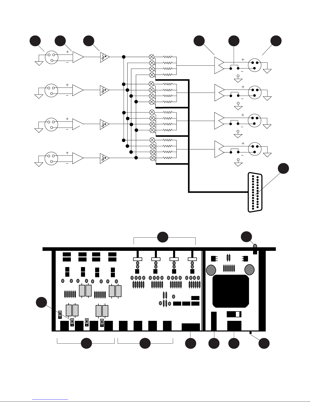
Figure 1.1: Front and Rear Panel Views of RMX-44
(Callouts refer to Figures 1.1, 1.2, and 1.3)
1. POWER LED - The front panel LED is illuminated
when the unit is on. The absence of an On/Off
switch is a performance safety feature, eliminating
accidental shutdown during operation.
2. INPUT CONNECTORS - XLR inputs, Pin 2 positive,
accept balanced or unbalanced signals from linelevel devices.
3. INPUT STAGE - The RF-suppressed input circuit is
electronically balanced (differential), and capable
of handling a maximum signal level of +24 dBu.
Balanced input impedance is approximately 80k
ohms, with a nominal input level range of -10 to
+8 dBu.
INPUT 2
INPUT 1
PIN 2 POSITIVE ON ALL
AUDIO CONNECTIONS
CONTROL PORT
8
FUSE
11
POWER
101182
10
CHASSIS
SERIAL NUMBER
9
7. OUTPUT CONNECTORS - XLR outputs, pin 2
positive, accommodate balanced or unbalanced
lines.
8. CONTROL PORT CONNECTOR - Female, 25-pin,
standard D-sub connector. Provides contacts for
jumpers or external switching to assign routing
of inputs to outputs. Latching contact closures
required (see SET-UP). Additional contacts
provide system mute capability and +15 VDC, 50
mA, output for powering LEDs, etc.
9. CHASSIS GROUND POST - Nuts on a threaded
stud enable the installer to conveniently secure a
ground wire to the chassis.
9
9
4. INPUT GAIN TRIM POTS - (labelled "INPUT 1,"
"INPUT 2,” etc.) Accessed through the front panel
with a small flat-blade screwdriver, these trim
pots adjust the input stage gain +/-15 dB, to
compensate for varying input signal levels.
5. OUTPUT STAGE - The output stage is electronically
balanced (push-pull) and AC coupled. Output
impedance is approximately 150 ohms. Each
output can provide a maximum level of +24 dBm
into a 600 ohm load, or +26 dBu unterminated.
6. BALANCED/UNBALANCED JUMPER BLOCKS These permit each output to be unbalanced
independently, if necessary (see SET-UP).
10. POWER CONNECTOR - Standard IEC 3-pin
connector for AC power cord. Use only with
grounded (3-wire) outlets. Cord sets are available
for all world connection standards.
11. FUSE HOLDER - Replace only with approved
type of fuse in a rating appropriate to the mains
voltage, as indicated on back panel (see
SPECIFICATIONS).
Page 2
RMX-44 BLOCK DIAGRAM
2 3 4 5 76
2 3 4 5 6 7
21
1
2
3
21
INPUT 1
S
OUTPUT A
S
3
2
1
A
B
3
21
3
21
3
FRONT PANEL
INPUT 2
INPUT 3
INPUT 4
Figure 1.2: Block Diagram of RMX-44 Mixing Matrix
4
OUTPUT B
S
OUTPUT C
S
OUTPUT D
CONTROL PORT
1
3
1
2
3
1
2
3
C
D
8
8
6
REAR
PANEL
27
Figure 1.3: Interior View of RMX-44 Mixing Matrix
Page 3
10118
9
 Loading...