

PRM-8
™
PAGE ROUTING MODULE
Installation
&
Operation
Manual

TABLE OF CONTENTS
PRM-8 INTRODUCTION .................................................................................................................. 1
PRM-8 CALLOUTS .......................................................................................................................... 2
PRM-8 BLOCK DIAGRAM ................................................................................................................ 3
PRM-8 SET-UP ................................................................................................................................ 4
PRM-8 SET-UP (CONTINUED) ......................................................................................................... 5
PRM-8 CONNECTIONS ................................................................................................................... 6
PRM-8 CONNECTIONS (CONTINUED) ............................................................................................. 7
PRM-8 PROGRAMMING .................................................................................................................. 8
PRM-8 PROGRAMMING (CONTINUED)............................................................................................ 9
PRM-8 PROGRAMMING (CONTINUED)........................................................................................... 10
TYPICAL PAGING CONTROL PANEL ............................................................................................... 11
PRM-8 SET-UP NOTES ................................................................................................................... 12
PRM-8 SPECIFICATIONS ............................................................................................................... 13
OXMOOR FACTORY SERVICE ......................................................................................................... 14
OXMOOR TWO YEAR LIMITED WARRANTY ..................................................................................... 14
CONTACT OXMOOR ....................................................................................................................... 14

PRM-8 INTRODUCTION
•Multi-channel zone-page feature
• All-page capability
• Eight program channels
•Mic/line selectable page input
• Second line-level page input
• Individual channel page-level controls
• Adjustable program ducking
• Individual channel ramp-up/down adjustments
• Zone selection control by momentary or maintained closure
• PA-422 serial control capability
• Provision for real-time LED tally indicators
• Removable terminal blocks for easy wiring
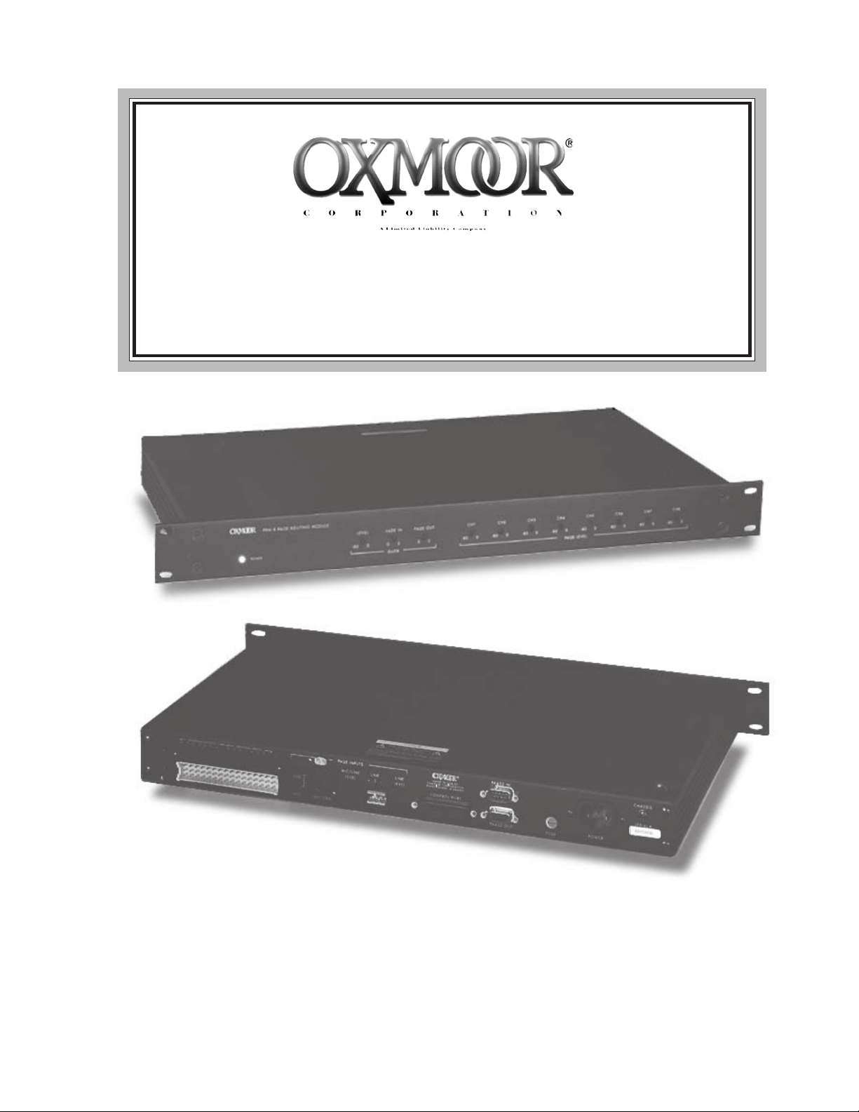
The eight-channel PRM-8 Page Routing Module simplifies page routing within multiple-zone sound systems.
Page inputs are easily routed to any one, or any combination, of the module’s eight program channels.
Upon initiation of a page, program audio at each selected channel is automatically faded to a user-determined level and mixed with the page signal. Upon
completion of a page the program audio on each channel is ramped smoothly back to its original level.
Each of the two PRM-8 page inputs may function as a
Zone Page and/or an All Page input as determined by
internal dip switches. An input assigned the All Page
function takes priority over the Zone Page input.
Accessed through the control port, the Zone Page Enable control routes the zone page input to the selected
program channels. During this page, the program audio
of each selected channel is ducked as determined by the
Duck Level.
Similarly, the All Page Enable control routes the All
Page input to all program channels. During this page,
the program audio of all channels is ducked as determined by the Duck Level.
to its original level upon completion of a page. Page
Level gain controls provide independent page level settings for each program channel.
Controls on the rear of the PRM-8 include a "Mic, Line"
switch for configuring the page Mic/Line input to accept
either a microphone source or a line-level source and
screwdriver-adjustable attenuators for both page inputs.
A Control Port allows the use of contact closures, momentary or maintained (user selectable), for zone page
selection and zone page clear. Zone page enable and all
page enable always require a maintained closure. DC
power is also present for adding LED tally indicators for
all control functions.
The PRM-8 is ideally suited to solving the complex
patching requirements of paging within room combining
systems. When linked to Oxmoor’s MCS Room Combining System through PA-422 ports, the Page Module
tracks room combining changes. As a result, a page
routed to one channel within a combined group will go
to all channels in the group. Besides allowing communication between the PRM-8 and the MCS-Mainframe, the
PA-422 ports make possible the utilization of an alternative controller.
In some installations it is desirable to prevent the All
Page signal from being heard in certain zones. An All
Page Source dip switch removes the All Page source
from selected channels during an All Page function. All
channels will continue to duck and ramp the program
source during an All Page.
Screwdriver-adjustable controls on the front panel of the
compact, 1U chassis include Duck Level for setting the
level to which program audio is attenuated during a
Zone Page and All Page. Fade In adjusts the time required for the program audio to reach the duck level
upon initiation of a page. Fade Out adjustment determines the time required for the program audio to return
All PRM-8 audio inputs and outputs are electronically
balanced and accommodate either balanced or unbalanced lines. Terminal block connectors insure easy installation and solid mechanical connection for the eight
program channel inputs and outputs as well as the linelevel page input. The page Mic/Line connection is
through a standard female XLR-type connector.
The PRM-8 Page Module brings simplicity to system design, installation and operation, along with the uncompromising performance and reliability for which
Oxmoor products are well known and respected.
Page 1
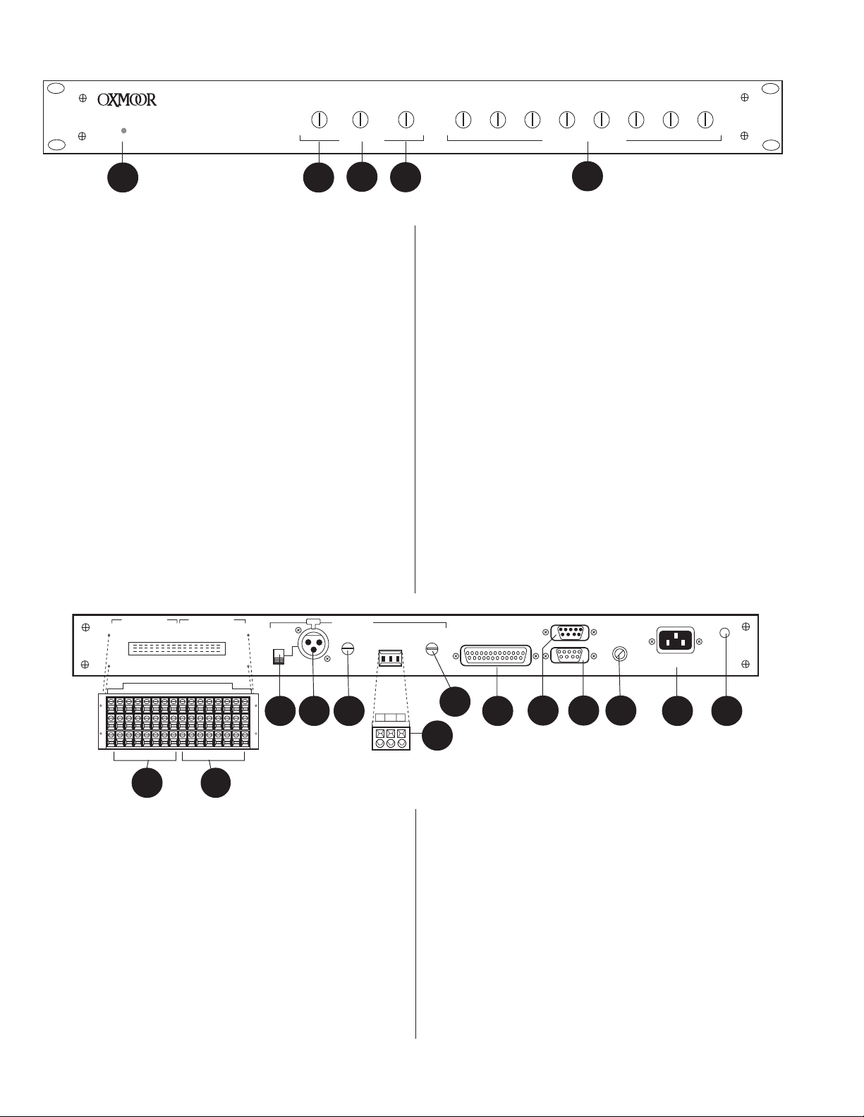
PRM-8 CALLOUTS
PRM-8 PAGE ROUTING MODULE
POWER
1
LEVEL FADE IN FADE OUT
0-80 0 5 0 5
DUCK
2
3
Figure 1.0: Front Panel View
1. POWER STATUS LED - Indicator for AC Power On.
2. DUCK LEVEL - Duck level control pot, accessed through the
front panel with a small flat-blade screwdriver, adjusts the
level to which program material is attenuated during a
page. Range is from 0 (no ducking) to -80 dB.
3. FADE IN - Accessed through the front panel with a small
flat-blade screwdriver, sets the time required, during a
page, for the program material to be attenuated to the
level established by the DUCK LEVEL control.
4. FADE OUT - Accessed through the front panel with a small
flat-blade screwdriver, sets the time required for the
program material to return to its prior level upon
cessation of a page.
5. PAGE LEVEL - Accessed through the front panel with a
small flat-blade screwdriver, these attenuators adjust
page level, from 0 to -80 dB, in each zone individually.
6. PROGRAM OUTPUTS - Audio outputs, terminal block
connections with mating connector, electronically
balanced, accommodate balanced or unbalanced lines.
Recommended load impedance is 600 ohms or greater.
Maximum output level is +24 dBu.
CH1 CH 2 CH 3 CH 4 CH 5 CH 6 CH 7 CH 8
-800-800-800-800-800-800-800-80
4
PAGE LEVEL
5
10. MIC/LINE LEVEL - Accessed through the back panel with a
small flat-blade screwdriver, adjusts the MIC/LINE input
for varying input signal levels.
11. LINE IN - Page input, terminal block connections with
mating connector, electronically balanced input, accepts
balanced or unbalanced signals from line-level devices.
Normal input level is +4 dBu with a maximum input level
of +24 dBu.
12. LINE LEVEL - Accessed through the back panel with a small
flat-blade screwdriver, adjusts the LINE input for varying
input signal levels.
13. CONTROL PORT - Female, 25-pin, standard D-sub connector.
Provides connections for external switching of: Zones for
zone paging, Zone Page Enable, All Page Enable, and Zone
Page Clear. Also provides tally connections for all control
functions.
14. PA-422 IN - Male, 9-pin D-sub connector. This port
connects to the PA-422 OUT of the MCS-MCP Master
Control Panel, an MCS-IB Interface Box or other PA-422
control devices.
0
PROGRAM OUTPUTS
8765432187654321
+
–
S
6
PROGRAM INPUTS
7
LINE
MIC
8
PUSH
MIC/LINE
9 10
PAGE INPUTS
LEVEL
+–
Figure 1.1: Rear Panel View
7. PROGRAM INPUTS - Audio inputs, terminal block
connections with mating connector, electronically balanced,
accept balanced or unbalanced signals from line-level
devices. Normal input level is +4 dBu with a maximum input
level of +24 dBu.
8. MIC, LINE - Switch configures the MIC/LINE input to
accept either a microphone-level or a line-level source.
9. MIC/LINE - Page input, XLR-F type, Pin 2 positive,
electronically balanced, accepts balanced or unbalanced
signals. Normal input level is dependent on the MIC,
LINE switch setting. Microphone input level is -50 dBu
with a maximum input level of -20 dBu. Line input level
is +4 dBu with a maximum input level of +24 dBu.
OXMOOR
MADE IN USA BY
OXMOOR CORPORATION
12
BIRMINGHAM, ALABAMA
CONTROL PORT
13
LINEMIC/LINE
LINE
LEVEL
S
14
PA-422 IN
PA-422 OUT
15
FUSE
16
POWER
17
CHASSIS
SERIAL #
18
11
15. PA-422 OUT - Female, 9-pin D-sub connector. It is used to
carry the PA-422 data to the next PA-422 device.
16. FUSE HOLDER - Replace only with approved type of fuse
in a rating appropriate to the mains voltage, as indicated
on back panel. (See SPECIFICATIONS).
17. POWER CONNECTOR - Standard IEC 3-pin connector for
AC power cord. Use only with grounded (3-wire) outlets.
Cord sets are available for all world connection
standards.
18. CHASSIS GROUND POST - A screw with a star washer
enables the installer to secure a ground wire to the
chassis.
Page 2
Page
Inputs
PRM-8 BLOCK DIAGRAM
Line
21
Mic/Line
Program
Inputs
3
Mic/Line Switch
Page
Level
CH. 1
Duck
Page
Level
CH. 2
Duck
Page
Level
CH. 3
Duck
Page
Level
CH. 4
CH. 5
Duck
Duck
Page
Level
Program
Outputs
Page
Level
CH. 6
Duck
Page
Level
CH. 7
Duck
Line
Mic/Line
ON ON
Zone Page
Input
SW1SW1
All Page
Input
CH. 8
12345678
SW3
All Page
Source
Page
Level
Duck
On–Board Microprocessor
ON
CH.
In
Level
Figure 1.3: Block Diagram
Page 3
Out
Toggle
SW1
••••••••••••••••••••
•••••••••••••••••••
Control
Port
Maintained
Send/Receive
ON
CH.
SW2
•••••
••••
12345678
In
PA-422Duck Fade
•••••
••••
Out

PRM-8 SET-UP
OXMOOR CORPORATION
MADE IN USA
PRM-8
COPYRIGHT 1994
PCB # 1300129
REVISION A
SW2 SW3
SW1
230
ON
12345678
ON
12345678ON12345678
SW6
POWER LED
SW 1
SW 3
SW 2
AC POWER TRANSFORMER
PRM-8 SET-UP OVERVIEW
(Refer to Figure 2.1)
The PRM-8 has three internal dip switches that may be used to
configure its operation for different system requirements. Before
installing the PRM-8, refer to the switch function description
below to determine the switch positions best suited to your
system requirements. Refer to page 10 for a typical control panel
configuration and its operation.
CAUTION!
Hazardous voltages are present inside the chassis.
Before opening the case to gain access to the printed
circuit board, always remove the power from the unit by
disconnecting the AC power cord.
If changes are required:
1. Disconnect the AC power cord.
2. Remove the screws that secure the top cover and set the cover
aside.
3. Use the front panel Power LED and the AC Power
Transformer as reference points to locate SW1, SW2 and SW3
which are located on the component side of the PRM's printed
circuit board
SW1 SET-UP PROCEDURE
(Refer to Figure 2.0)
Switch SW1 determines if: A manual Zone Page Clear line is to
be used; The system is to store the Zone Page selections after a
zone page; The Channel Select is to operate with momentary or
maintained closures; The Page inputs are to be used as All Page,
Zone Page or both
SW1
ON
12345678
.
.
SW1: Shipped from factory configured as shown.
Note: The Zone Page Clear function can be used only
if the Control Port is set for MOMENTARY
operation (#4 ON).
Figure 2.1: SW1, SW2 and SW3 Location on Printed Circuit Board
SW2 SET-UP PROCEDURE
(Refer to Figure 2.2)
Switch SW2 determines the PA-422 address. When the PA422 port is to be used, the PRM-8's PA-422 address should be
set to the same address as the controlling device. PA-422
requires that a device's address be between 1 and 250.
SW2
ON
12345678
1
2
4
8
16
32
64
128
SW2: Shipped from factory with
PA -422 set to address 2.
PA-422 Address
Figure 2.2: Factory Set-Up for SW2
1*Off = Not used, set to Off position
2*Off = Not used, set to Off position
3 Off = Zone Page selection is NOT stored
*On=Zone Page selection is stored
4*Off = Channel Select set for MAINTAINED closures
On = Channel Select set for MOMENTARY closures
5*Off = Mic/Line input NOT used as All Page
On = Mic/Line input used as All Page
6 Off = Line input NOT used as All Page
*On=Line input used as All Page
7 Off = Mic/Line input NOT used as Zone Page
*On=Mic/Line input used as Zone Page
8*Off = Line input NOT used as Zone Page
On = Line input used as Zone Page
* Indicates factory settings.
Figure 2.0: Factory Set-Up for SW1
Page 4
SW3 SET-UP PROCEDURE
(Refer to Figure 2.3)
SW3 allows individual channels to NOT receive the All
Page source. Those channels switched OFF will continue to
mute and ramp the program source during an All Page, but
will not receive the All Page source.
SW3
ON
12345678
1
2
3
4
5
6
7
8
SW3: Shipped from factory with all
channels set to receive the All
Page source (all channels ON).
PRM-8 Program Channels
Figure 2.3: Factory Set-Up for SW3

PRM-8 SET-UP (CONTINUED)
SW3
ON
12345678
1
2
3
4
5
6
7
8
PRM-8 Program Channels
SW2
ON
12345678
1
2
4
8
16
32
64
128
PA-422 Address
SW1
ON
12345678
DIRECT MODE SET-UP
The PRM-8 can be programmed to allow page routing to any
channel without the use of the Zone Page Enable control line. In
this mode the Fade In and Fade Out settings are ignored and any
combination of channels may be selected at any time. When a
program channel is selected (using a Channel Select control line)
the program audio is immediately ducked to the Duck Level
setting and the PRM's Zone Page input is routed to the selected
channel(s).
To program the PRM-8 for the Direct Mode operation:
A. Remove the AC power from the unit.
B. Set SW1, switch number 4 to the off (MAINTAINED)
position.
C. Hard-wire the Zone Page Clear line (pin 14 on the Control
Port) to common.
D. Restore the AC power to the unit.
PROGRAM OUTPUT BALANCED/UNBALANCED SET-UP
(Refer to Figure 2.4)
The PRM-8 is configured from the factory for balanced audio
outputs. A jumper is provided for each channel to allow easy
conversion to an unbalanced configuration.
CUSTOM SET-UP
(Refer to Figures 2.6, 2.7, 2.8 and 2.9)
Use the templates below to record custom set-ups of the
PRM-8:
Figure 2.6: SW1 Set-Up Template
BALANCED SET UP
Arrows Pointing To Rear Panel Of PRM-8
UNBALANCED SET UP
Figure 2.4: Program Output Jumper Set-Up
PROGRAM OUTPUT FACTORY SET-UP
(Refer to Figure 2.5)
Located next to the PRM-8's Program Output connector on the
circuit board, the jumpers are labeled as follows:
P9 = Channel 1
P16 = Channel 2
P11 = Channel 3
P10 = Channel 4
P13 = Channel 5
The diagram below illustrates the factory set-up for the
balanced/unbalanced jumpers.
P12 = Channel 6
P14 = Channel 7
P15 = Channel 8
Program Output Jumpers
P15
P14
P12
P13
P10
P11
P16
Figure 2.7: SW2 Set-Up Template
Figure 2.8: SW3 Set-Up Template
Program Output Jumpers
P15
P14
P12
CH: 8
CH: 7
CH: 6
CH: 5
P13
P10
CH: 4
P11
CH: 3
P16
CH: 2P9CH: 1
CH: 8
Figure 2.9: Program Output Jumpers Set-Up Template
CH: 7
CH: 6
CH: 5
CH: 4
CH: 3
CH: 2P9CH: 1
Figure 2.5: Factory Set-Up for Output Jumpers
Page 5

PROGRAM OUTPUTS PROGRAM INPUTS
8765432187654321
+
–
PRM-8 CONNECTIONS
LINE
PUSH
PAGE INPUTS
LEVEL
LINEMIC/LINE
S
+–
LINE
LEVEL
S
Figure 3.0: Program Inputs and Outputs View
PROGRAM INPUT AND OUTPUT CONNECTIONS
(Refer to Figure 3.0)
The PRM-8 Page Module provides connections for eight
program channels. Upon initiation of a page, the page inputs
are routed to any one, or any combination, of these program
channels.
The Program Input and Output connections are made through
a 48-pin screw terminal block mating connector. NOTE: Make
sure that the two mounting screws (shipped with the connector) are
used to secure the 48-pin screw terminal to the enclosure.
1. PROGRAM INPUTS: (S) = Shield, (+) = High, (–) = Low,
electronically balanced input, accepts balanced or
unbalanced signals from line-level devices. Nominal input
level is +4 dBu with maximum input level of + 24 dBu.
2. PROGRAM OUTPUTS: (S) = Shield, (+) = High, (–) = Low,
electronically balanced output accommodates balanced or
unbalanced lines. Recommended load impedance is 600
ohms or greater. Maximum output level is +26 dBu.
MIC/LINE
MIC
Figure 3.3: Page Inputs View
PAGE INPUT CONNECTIONS
(Refer to Figure 3.3)
The PRM-8 Page Module provides connections for two page
inputs. Page inputs are easily routed to any one, or any
combination, of the module's eight program channels.
1. MIC/LINE: XLR input, Pin 1 = Shield, 2 = High, 3 = Low,
accepts balanced or unbalanced signals from mic-level or
line-level audio devices.
MIC, LINE: Set switch to MIC position for mic-level or LINE
position for line-level source.
MIC/LINE LEVEL: Use a small flat-blade screwdriver to
adjust the MIC/LINE input for various input signal levels.
2. LINE: (S) = Shield, (+) = High, (–) = Low, accepts balanced
or unbalanced signals from line-level audio devices. The
connections are made through a 3-pin cage-clamp
connector. The cage-clamp spring clamps the wire
providing quick and easy termination.
PROGRAM INPUT AND OUTPUT WIRING SCHEMES
(Refer to Figures 3.1 and 3.2)
The diagrams below illustrate the correct wiring of balanced
and unbalanced program inputs and outputs.
BALANCEDBALANCED
BALANCED
BALANCEDBALANCED
UNBALANCEDUNBALANCED
UNBALANCED
UNBALANCEDUNBALANCED
+
–
S
+
–
S
+
–
S
+
–
S
Figure 3.1: Program Input Wiring Schemes
BALANCEDBALANCED
BALANCED
BALANCEDBALANCED
HIGH
LOW
SHIELD
UNBALANCEDUNBALANCED
UNBALANCED
UNBALANCEDUNBALANCED
NC
HIGH
LOW
Figure 3.2: Program Output Wiring Schemes
HIGH
LOW
SHIELD
HIGH
LOW
NC
NOTE: The unbalanced
output configuration
is valid ONLY if the
Balanced/Unbalanced
output jumper block
has been set to the
unbalanced position.
See page 6, Figure 2.4.
LINE LEVEL: Use a small flat-blade screwdriver to adjust the
LINE input for various input signal levels.
PAGE INPUT WIRING SCHEMES
(Refer to Figure 3.4)
The diagram below illustrates the correct wiring of balanced
and unbalanced page inputs.
LINE IN
MIC/LINE IN
LINE IN
MIC/LINE IN
–
3
S
1
+
2
–
3
S
1
+
2
Figure 3.4: Page Input Wiring Schemes
BALANCEDBALANCED
BALANCED
BALANCEDBALANCED
UNBALANCEDUNBALANCED
UNBALANCED
UNBALANCEDUNBALANCED
LOW
SHIELD
HIGH
LOW
NC
HIGH
Page 6

PRM-8 CONNECTIONS (CONTINUED)
N
LINE
LEVEL
Pin 25Pin 25
Pin 25
Pin 25Pin 25
OXMOOR
MADE IN USA BY
OXMOOR CORPORATION
BIRMINGHAM, ALABAMA
CONTROL PORT
PA-422 OUT
Pin 1Pin 1
Pin 1
Pin 1Pin 1
PA-422 IN
Figure 3.5: Control Port View
CONTROL PORT CONNECTIONS
(Refer to Figures 3.5, 3.6 and 3.7)
The PRM-8 Page Module Control Port provides connections
for external switching of zones for Zone Paging, Zone Page
Enable, All Page Enable, and Zone Page Clear. Also provides
tally connections for all control functions. NOTE: The Zone
Page Enable and the All Page Enable tally lines are activated only
after the duck level setting is reached, as established by the front
panel control.
All Channel Select functions are operated by contact closures,
either "momentary" or "maintained" depending on SW1 (see
page 5) setting. Zone Page Enable and All Page Enable
functions are operated by "maintained" contact closures.
Pin Function
1Common
2Common
3 Bias for Back EMF
4 All Page Enable
5 Channel 1 Select
6 Channel 2 Select
7 Channel 3 Select
8 Channel 4 Select
9 Channel 5 Select
10 Channel 6 Select
11 Channel 7 Select
12 Channel 8 Select
13 Zone Page Enable
Figure 3.6: Control Port Pin-Out
Pin Function
14 Zone Page Clear
15 All Page Tally
16 Zone Page Tally
17 Channel 1 Select Tally
18 Channel 2 Select Tally
19 Channel 3 Select Tally
20 Channel 4 Select Tally
21 Channel 5 Select Tally
22 Channel 6 Select Tally
23 Channel 7 Select Tally
24 Channel 8 Select Tally
25 +15 VDC
OOR
USA BY
ORPORATION
M, ALABAMA
OL PORT
PA-422 IN
PA-422 OUT
FUSE
POWER
Figure 3.8: PA-422 Serial Control Port View
PA-422 SERIAL CONTROL PORT CONNECTIONS
(Refer to Figures 3.8, 3.9 and 3.10)
All PRM-8 functions can be controlled through the PA-422
serial control port. See Wiring detail below.
Use Belden #9681 or equivalent.
+
1
6
DSR
_
2
7
3
FEMALE
8
+
4
9
RxD
_
5
MALE
+
1
+
DSR
RxD
6
_
2
DTR
_
7
3
+
8
+
4
TxD
_
9
_
5
DRAIN (SHIELD) WIRE
+
DTR
_
+
TxD
_
Figure 3.9: PA-422 Serial Control Port Wiring
PA-422 IN
PA-422 Controller
PA-422 OUT
Function
Description
All Page Enable Initiates All Page
Use Belden #9681
or
Equivalent
PA-422 OUT of Controller
Channel X Select Assigns channel to receive the Zone
Page
Channel X Tally Provides open-collector closure to
PA-422 IN of PRM-8 Page Module
common when control function is
active
OXMOOR
Zone Page Enable Initiates Zone Page
Common Logic Common
MADE IN USA BY
OXMOOR CORPORATION
BIRMINGHAM, ALABAMA
CONTROL PORT
Zone Page Clear Clears Channel X Selections
PA-422 IN
PA-422 OUT
FUSE
CHASSIS
SERIAL #
POWER
+15 VDC DC voltage for Tally LEDs
Figure 3.10: PA-422 Typical Connection Scheme
Figure 3.7: Control Port Functions and Descriptions
Page 7

PRM-8 PROGRAMMING
1.0 PRM-8 PROGRAMMING OVERVIEW
This document is a PA-422 communications reference
for those interested in designing their own custom
software to control the OXMOOR PRM-8 system.
Intended as a supplement to the PA-422 standard
documentation (which describes in detail the operation
of PA-422), this text describes those commands which
are used with the PRM-8 . These commands are described
in a manner consistent with the PA-422 standards draft:
each command is introduced and its exact usage given in
a procedural, step-by-step fashion. Also included are
the data formats associated with each command.
2.0 DEVICE CONTROL LANGUAGE STRUCTURES
2.1 Transmit All Data - 81 hex
This command sends the data necessary to specify the
operational mode and channel configurations of the
PRM-8. The data transmitted includes the status of link
switches, device mode of operation, channel selection
for page function and enable/disable page function. To
send this command the controller must:
1. Transmit the address of the desired device.
2. Wait until DSR is set or 250 msec timeout period
has elapsed.
3. Set DTR.
4. Get DT (device-type code; 31 hex).
5. Get ID (mfg.’s identification code; 29 hex).
6. Transmit 81 hex (command code).
7. Transmit the data as shown in the data structure
description (see section 3).
8. Get COMSTAT (should be 00 hex if successfully
executed).
9. Verify DSR is reset by addressed device.
10. Reset DTR.
3.0 DEVICE CONTROL LANGUAGE (DCL) DATA
STRUCTURES
This section details the exact data streams that should be
sent with each PA-422 command to correctly
communicate with the desired device. Each data structure
is presented in the following format:
Data Transmitted:
(the data that should be sent with the command)
Byte# = Data stream position
Valid Data Range = Valid values for byte
Description = Information byte contains
Data Received:
(the data returned from the desired device).
Byte# = Data stream position
Valid Data Range = Valid values for byte
Description = Information byte contains
NOTE: All numbers in the data fields are decimal unless
noted otherwise.
2.2 Update Parameter of Device Channel - 96 hex
This command allows the controlling device to adjust
program source fade levels and fade in/out times of the
PRM-8.
1. Transmit the address of the desired device.
2. Wait until DSR is set or 250 msec timeout period
has elapsed.
3. Set DTR.
4. Get DT (device-type code; 31 hex).
5. Get ID (mfg.’s identification code; 29 hex).
6. Transmit 96 hex (command code).
7. Transmit the data as shown in the data structure
description (see section 3).
8. Get COMSTAT (should be 00 hex if successfully
executed).
9. Verify DSR is reset by addressed device.
10. Reset DTR.
Page 8

PRM-8 PROGRAMMING (CONTINUED)
3.1 Transmit All Data (81 hex)
Data Transmitted:
Byte# = 1
Valid Data Range = 0-2
Description = Page Source Input Select
0 = Mic/Line Level Input
1 = Line Level Input
2 = Both Mic/Line and
Line Level inputs
activated
Byte# = 2
Valid Data Range = 0 or 2
Description = Operational Mode Status
0 = Normal PRM-8
Application
1 = MCS Room Combining
System Application
2 = Direct Mode
Application
Byte# = 3
Valid Data Range = 0 or 1
Description = PRM-8 Paging Mode
0 = Page Function Disable
1 = Page Function Enable
Byte# = 5 through 15
Valid Data Range = 0-FF hex
Description = MCS Room Combining
System Link switch
settings
Room combinations for
each of the 11 link
switches. If a link switch is
inactive, the byte for that
switch should be zero.
Thus, if link switch one is
active and it combines
rooms 1 and 2, then byte 5
should be 00000011. Note
that byte 5 corresponds to
link switch 1, and byte 15
corresponds to link switch
11. If an MCS Room
Combining System is not
used, then byte 2
(operational mode status
byte) is zero. Bytes 5
through 15 are still
required to be transmitted,
but the data is ignored by
PRM-8.
Byte# = 4
Valid Data Range = 0-FF hex
Description = Channel Select for Page
Mode, i.e., channels 1-8.
Each bit corresponds to the
appropriate channel
desired. For example:
00010101 will route the
initiated page to channels
5, 3, and 1. Bit 8 (MSB0 is
channel 8; bit 1 (LSB) is
channel 1.
Data Received: none
Page 9

PRM-8 PROGRAMMING (CONTINUED)
3.2 Update Parameter of Device Channel (96 hex)
Data Transmitted:
Byte# = 1
Valid Data Range = 0 or 1
Description = 0 = Enable front panel trim
pots for Page function
1 = Disable trim pots and use
PA-422 data for Page
function
Byte# = 2
Valid Data Range = 0-FF hex
Description = Program source level
defined for all 8 channels.
(0 to -48dBu, -80dBu = off)
Program source attenuation
levels can be calculated as
follows:
Attenuation (dBu) = 20 Log [
(Vin / 0.7747) (decimal value /
256)]
For example:
0F hex (15 decimal) = value
transmitted 0.7747v = Vin input
-24dBu = 20 Log[ (1) (15 /256) ]
Byte# = 4
Valid Data Range = 0-FF hex
Description = Program source fade out time
for enabled page function.
(0 to 5 seconds)
FF hex = 5 sec. fade out time
0F hex = 2.5 sec. fade out time
00 hex = 0 sec. fade out time
Data Received: none
Other example values for input
voltage of 0.7747v (Vin) are:
FF hex equals 0 dBu attenuation
0F hex equals -24 dBu attenuation
01 hex equals -48 dBu attenuation
00 hex equals -80 dBu attenuation
Byte# = 3
Valid Data Range = 0-FF hex
Description = Program source fade in time
after page function isdisabled.
(0 to 5 seconds)
FF hex = 5 seconds fade in time
0F hex = 2.5 sec. fade in time
00 hex = 0 seconds fade in time
Page 10

TYPICAL PAGING CONTROL PANEL
Illustrated below is a typical control panel that could be used with Oxmoor’s PRM-8 Page Routing Module. While
there are many other ways of controlling Oxmoor's page module, the illustration includes the functions most often
desired.
Two types of paging are possible with this panel. Zone Page distributes a page to zones selected with the Zone Select
switches. All Page sends the page to all zones. LED tally indicators, incorporated into each push-button, provide a
visual confirmation of the status of each function.
ZONE 1 ZONE 2 ZONE 3 ZONE 4 ZONE 5 ZONE 6 ZONE 7 ZONE 8
Zone Select
Switches
ZONE PAGE ALL PAGE
Page
Switch
Zone Select Switches
A page can be sent to any one or any combination of
zones. Use the Zone Select switches to determine which
zones will receive a page. These buttons function in a
“push-on/push-off” fashion.
Select zones to receive a page by pushing each
appropriate Zone Select switch once. The LED will turn
on, indicating that the zone has been selected. To remove
a zone that has been selected, simply push the appropriate
zone’s button once.
Once a zone or zones have been selected, a Zone Page
may be initiated.
Note: An Illuminated LED indicates only that the zone is
programmed to receive a page, not that the PRM-8's page
input is on.
Page Switch
To page, press and hold the Page switch. The Page
Switch’s LED will turn on, indicating that a page is in
progress. As long as the Page switch is held down, the
page input will be on and the page message will be
directed to all selected zones.
All Page
Switch
When the page is complete, release the Page switch.
The LED on the Page switch will be turned off,
indicating the page input is off.
Note: As long as the Page Switch's LED is on, no
additional zones can be added or deleted from the
setup.
All Page Switch
To send a page to all zones simultaneously, push and
hold the All Page switch. The All Page switch’s LED
will illuminate, indicating that a page is in process. The
All Page function overrides whatever selections have
been made at the Zone Select switches. As long as the
All Page switch remains depressed, the page input will
be on and the page message will be directed to all
zones, whether they have been selected or not.
When the All Page is complete, release the All Page
switch. The LED on the All Page switch will be turned
off, indicating the all page input is off.
Page 11

PRM-8 SET-UP NOTES
Page 12

PRM-8 SPECIFICATIONS
FREQUENCY RESPONSE 20 Hz to 20 kHz ....................................... +0, -0.3 dB
HUM AND NOISE Ref. +4 dBm Output @ Unity Gain -85 dB (20 Hz to 20 kHz, Unweighted)
DISTORTION THD + Noise and IMD* ........................ -80 dB/0.01%
CROSSTALK Channel to Channel ............................... -80 dB (20 Hz to 20 kHz)
PROGRAM INPUTS Type ............................................................ Electronically Balanced (RF Suppressed)
Connectors .................................................. Screw Terminal Blocks with Mating Connector
Input Impedance ........................................ 80 K Ohms
Input Sensitivity ......................................... Nominal +4 dBu, Maximum +24 dBu
PROGRAM OUTPUTS Type ............................................................ Electronically Balanced (RF Suppressed)
Connectors .................................................. Screw Terminal Blocks with Mating Connector
Source Impedance ...................................... 150 Ohms (75 Ohms/Side)
Recommended Load Impedance .............. 600 Ohms or Greater
Maximum Output Level ............................ Ref. 1 kHz @ Rated THD
Terminated w/600 Ohms ........................ +24 dBm (All Outputs Driven Simultaneously)
Unterminated ............................................ +26 dBu
PAGE MIC/LINE INPUT Type ............................................................ Electronically Balanced (RF Suppressed)
Connectors .................................................. Female XLR, Pin 1 Shield (Chassis), Pin 2 +, Pin 3 –
Input Impedance ........................................ 1.5 K Ohms
Mic. Input Sensitivity ................................. Nominal -50 dBu
Mic. Gain Control Range ........................... -50 dB to 0 dB (Ref. 0 dBu Output)
Line Input Sensitivity ................................. Nominal +4 dBu, Maximum +24 dBu
Mic/Line Switch ......................................... Sets Input for Microphone or Line-Level Source
PAGE LINE INPUT Type ............................................................ Electronically Balanced (RF Suppressed)
Connectors .................................................. Cage-Clamp Connector with Mating Connector
Input Impedance ........................................ 80 K Ohms
Input Sensitivity ......................................... Nominal +4 dBu, Maximum +24 dBu
Gain Control Range .................................... ± 15 dB
PAGE LEVEL CONTROLS Ref. +4 dBm Output @ Unity Gain 0 to -80 dB (Accessed Through Front Panel)
DUCK ADJUSTMENTS Attenuation............................................... 0 dB to -80 dB (Variable)
Fade In........................................................ 0 to 5 Seconds (Variable)
Fade Out .................................................... 0 to 5 Seconds (Variable)
CONTROL PORT Connector .................................................. 25-pin D-sub, Female
Input Type ................................................... Active Low, Internally Pulled Up
Logic Action
Channel Select "Selectable" ...................... Momentary or Maintained Closure to Common
All Page & Zone Page .............................. Maintained Closure to Common
Logic Levels ................................................ Low < .8 Volts, High > 2.4 Volts
Maximum Sink Current ............................. 1 mA
Maximum Cable Length ............................ 600 m (2000 ft.), #22 AWG
Switching Time ........................................... 50 ms
Power Output ............................................. +15 VDC ±0.1 V, 50 mA
COMMUNICATION Protocol ...................................................... PA-422
Input Connector .......................................... 9-pin D-sub, Male
Output Connector ...................................... 9-pin D-sub, Female
MAINS POWER Power Requirements.............................. 100 to 125 VAC or 200 to 230 VAC, 50/60 Hz
MECHANICAL Overall Dimensions ............................... 44 H x 482 W x 254 D mm
(1.72 H x 19 W x 10 D in)
Finish ........................................................... Textured Black Paint
Weight ......................................................... Shipping: 6.3 Kg (14 lb) Net: 5.9 Kg (13 lb)
*SMPTE Method; 60 Hz + 7 kHz mixed 4:1. ** Input terminated w/600 ohms, unity gain, adjacent channel driven to +4 dBm output.
Specifications subject to change without notice.
Page 13

OXMOOR FACTORY SERVICE
For service information contact:
Oxmoor Product Service Department
309 Cahaba Valley Parkway
Birmingham, Alabama 35124
E-mail: info@oxmoor.com
Additional Installation & Operation Manuals are available from Oxmoor. Contact the
Oxmoor Sales Department for pricing and other ordering information. Consult
warranty statement for cautions concerning unauthorized service.
Telephone: (205) 982-8200
Toll Free: 1 (800) 262-6898
Fax: (205) 982-8250
Internet: www.oxmoor.com
OXMOOR TWO YEAR LIMITED WARRANTY
Oxmoor warrants that each Oxmoor electronic product shall be free from defects in workmanship
and materials and will, at its option, repair or replace any part of the product without charge
provided the product is delivered to Oxmoor within two years of date of original purchase from
or delivery by an authorized Oxmoor dealer. Excluded from this warranty are finish and
appearance items and malfunction resulting from abuse, from use that is not in accordance with
instructions, or operation under other than specified conditions. Also excluded are incidental or
consequential damages except where precluded by applicable law. This warranty provides the
customer with specific legal rights; there may also be other rights which vary from state to state.
Repair by other than Oxmoor Factory Service Department or its authorized service agency,
unauthorized modification, or the removal or defacing of the serial number will void this
warranty.
Products returned for factory warranty service must be prepaid and packaged in such a way as to
insure safe transit and must be accompanied by a sales slip or other valid proof of purchase date.
PRIOR AUTHORIZATION FROM OXMOOR IS REQUIRED FOR RETURN. Contact Oxmoor for
a Return Authorization (R.A.) Number and shipping information before returning product for
service.
CONTACT
OXMOOR
Oxmoor Corporation, LLC, 309 Cahaba Valley Parkway, Birmingham, AL 35124 USA
Toll Free 1 (800) 262-6898 Telephone (205) 982-8200 Fax (205) 982-8250 E-mail info@oxmoor.com
For 24-hour access to product specs and information visit Oxmoor's complete product line on the internet at www.oxmoor.com.
Oxmoor is a registered trademark of Oxmoor Corporation, LLC.
Specifications and design are subject to change without notice.
Oxmoor PRM-8 Page Routing Module
Rev. 3.1/073101 Part Number:1700015
 Loading...