

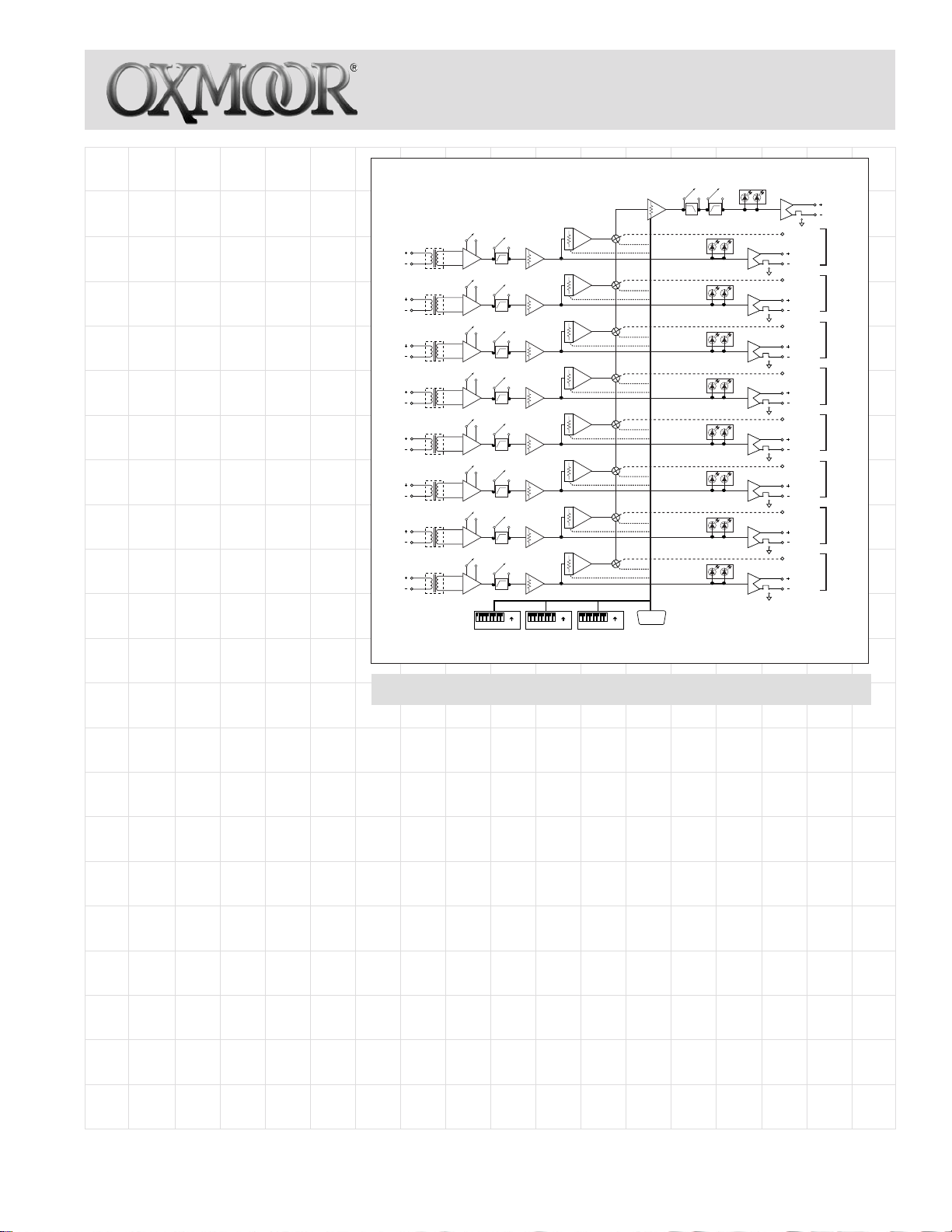
The MPM-81 Microphone Preamp Mixer
provides eight balanced microphone/
line level inputs. Each input can be
switched between microphone level or
line level.
There are eight Direct outputs and one
Mix Bus out. Each input can easily be
routed to the Mix Bus using a dedicated
control line for remote applications or
an internal dip switch for permanent
assignment. Any combination of the eight
inputs can be assigned to the Mix Bus.
The MPM-81 is ideal for use as an 8x1
mic/line mixer or as an 8x1 source selector. It may also be used as an eight microphone preamp input with eight direct
outputs while using the Mix Bus as a
monitor output.
Each input has a selectable Hi-Pass filter
that can be switched in or out. This HiPass filter can be used to reduce low
frequency noise from the microphone or
line inputs. Each input also has a ± 15 dB
trim pot which is located on the rear of
the unit. The trim pot can be used for
adjusting the microphone or line level
inputs for varying input signal levels. A
version of the MPM-81 is available with
input transformers.
All inputs and outputs are electronically
balanced and accommodate either balanced or unbalanced lines. Each output
provides Peak and Signal LED indicators. In addition, cage clamp connectors
are used to ensure easy installation and
solid electrical connections for the eight
program channel inputs and outputs and
the Mix Bus output.
Any input can be assigned to the Mix Bus
independent of other channels. Each
channel that is assigned to the Mix Bus
goes through its own VCA level control
and peak limiter. The VCA level control
for each channel is located on the front
panel of the MPM-81. The Mix Bus provides a master VCA level control which
is also on the front panel of the MPM-81.
The Mix Bus has separate high frequency
and low frequency tone controls. The 8
kHz high frequency tone control pro-
vides a ± 12 dB boost or cut, and the low
MPM™-81
MICROPHONE PREAMP/MIXER
HI PASS
MIC/LINE
TRANSFORMER
OPTION
CH. 1
TRANSFORMER
OPTION
CH. 2
TRANSFORMER
OPTION
CH. 3
TRANSFORMER
OPTION
CH. 4
TRANSFORMER
OPTION
CH. 5
TRANSFORMER
OPTION
CH. 6
TRANSFORMER
OPTION
CH. 7
TRANSFORMER
OPTION
CH. 8
FILTER
HI PASS
MIC/LINE
FILTER
HI PASS
MIC/LINE
FILTER
HI PASS
MIC/LINE
FILTER
HI PASS
MIC/LINE
FILTER
HI PASS
MIC/LINE
FILTER
HI PASS
MIC/LINE
FILTER
HI PASS
MIC/LINE
FILTER
ON
CH.
12345678
SW 9 SW 10 SW 11 CONTROL PORT
MPM-81 Microphone Preamp/Mixer
frequency 150 Hz tone control provides
a ± 12 dB boost or cut. Adjustment of
the tone controls is made using front
panel knobs.
Each channel can be assigned to the Mix
Bus either by providing a maintained
contact closure on the channel’s MIX
control line, or by using the internal dip
switch to permanently assign channels
to the Mix Bus. The MIX control line for
each channel is located within the
channel’s input/output cage clamp on
the rear panel.
The MPM-81 provides a Page feature
that allows one of the input channels
to be used as a page input. This Page
feature is only available through the
Mix Bus output and does not affect the
Direct output.
When using this Page feature, all chan-
TRIM CONTROL
TRIM CONTROL
TRIM CONTROL
TRIM CONTROL
TRIM CONTROL
TRIM CONTROL
TRIM CONTROL
TRIM CONTROL
12345678
VCA / LIMITER
VCA / LIMITER
VCA / LIMITER
VCA / LIMITER
VCA / LIMITER
VCA / LIMITER
VCA / LIMITER
VCA / LIMITER
ON
CH.
12345678
TONE CONTROL BY-PASS
PEAK
SIGNALPEAK
BAL/UNBALANCE
SIGNALPEAK
BAL/UNBALANCE
SIGNALPEAK
BAL/UNBALANCE
SIGNALPEAK
BAL/UNBALANCE
SIGNALPEAK
BAL/UNBALANCE
SIGNALPEAK
BAL/UNBALANCE
SIGNALPEAK
BAL/UNBALANCE
SIGNALPEAK
BAL/UNBALANCE
SIGNAL
BAL/UNBALANCE
MIX ASSIGN
DIRECT OUT
MIX ASSIGN
DIRECT OUT
MIX ASSIGN
DIRECT OUT
MIX ASSIGN
DIRECT OUT
MIX ASSIGN
DIRECT OUT
MIX ASSIGN
DIRECT OUT
MIX ASSIGN
DIRECT OUT
MIX ASSIGN
DIRECT OUT
ON
CH.
VOLUME CONTROL
••••••••
•••••••
nels can be assigned to the Mix Bus
except the channel that is selected as
the Page channel. When the Page channel is activated, it is routed to the Mix
Bus. All channels except the Page channel will then mute their audio if they
have been programmed to mute. Upon
completion of the page, all channels
return to their previous levels.
A control port provides connection for
remote volume control of channels 1 - 8
and the Mix Bus master volume. Each
remote volume control requires a 10K
pot and a DC voltage between +15
“Off” and 0 VDC “Full On.”
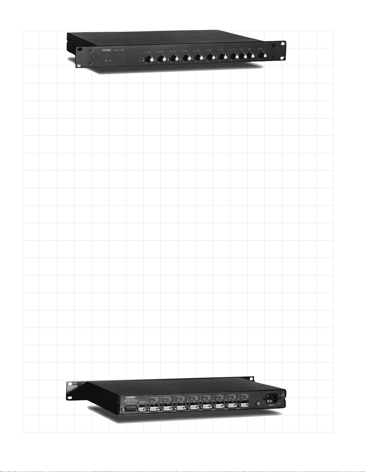
The compact 1U rack space MPM-81
brings simplicity to system design,
installation and operation, along with
the uncompromising performance and
reliability for which Oxmoor products
are known.
MIX OUT
CH. 1
CH. 2
CH. 3
CH. 4
CH. 5
CH. 6
CH. 7
CH. 8
Oxmoor Corporation, LLC, 309 Cahaba Valley Parkway, Birmingham, AL 35124 USA Toll Free: 1-800-262-6898
Phone: 205-982-8200 Fax: 205-982-8250 E-mail: info@oxmoor.com Internet: www.oxmoor.com
MPM-81™ SPECIFICATIONS
FREQUENCY RESPONSEFREQUENCY RESPONSE
FREQUENCY RESPONSE 20 Hz to 20 kHz ...................................................................... +0, -0.3 dB (Ref. +4 dBu)
FREQUENCY RESPONSEFREQUENCY RESPONSE
HUM AND NOISEHUM AND NOISE
HUM AND NOISE Ref. +4 dB, Input Terminated With 150 ohms,
HUM AND NOISEHUM AND NOISE
Output @ Unity Gain (20 Hz to 20 kHz, Unweighted)
Line Input, Direct Output ....................................................... -93 dBu
Microphone Input, Direct Output .......................................... -85 dBu
Line Input, Mix Output............................................................ -84 dBu
Microphone Input, Mix Output............................................... -80 dBu
DISTORTIONDISTORTION
DISTORTION THD + Noise and IMD*, Ref. 0 dB, Output @ Unity Gain
DISTORTIONDISTORTION
Line Input, Direct Output ....................................................... .01%
Microphone Input, Direct Output .......................................... .01%
Line Input, Mix Output............................................................ .035%
Microphone Input, Mix Output............................................... .035%
OFF ISOLATIONOFF ISOLATION
OFF ISOLATION Line Input Ref. 0 dBu ............................................................. 8 0 dB
OFF ISOLATIONOFF ISOLATION
Microphone Input Ref. -40 dBu............................................. 80 d B
CROSSTALKCROSSTALK
CROSSTALK Unity Gain, Ref. +4 dB output
CROSSTALKCROSSTALK
Channel to Channel ................................................................ -80 dB (20 Hz to 20 kHz)
MIC/LINE INPUTSMIC/LINE INPUTS
MIC/LINE INPUTS Type........................................................................................... Electronically Balanced (RF Suppressed)
MIC/LINE INPUTSMIC/LINE INPUTS
Connectors ............................................................................... Cage Clamps with Mating Connector
Input Impedance ..................................................................... 10 K Oh ms
Line Input Sensitivity .............................................................. Typical +4 dBu, Maximum +18 dBu
Microphone Input Sensitivity ................................................. Typical -40 dBu, Maximum -22 dBu
Mic/Line Switch....................................................................... Sets Input for Microphone or Line-Level Source
Mic/Line Trim Control Range ................................................ ± 15 dB (Ref. 0 dBu Output)
PROGRAM OUTPUTSPROGRAM OUTPUTS
PROGRAM OUTPUTS Type ........................................................................................... Electronically Balanced (RF Suppressed)
PROGRAM OUTPUTSPROGRAM OUTPUTS
Connectors ............................................................................... Cage Clamps with Mating Connector
Source Impedance .................................................................. 150 Ohms (75 Ohms/Side)
Recommended Load Impedance ........................................... 600 Ohms or Greater
Maximum Output Level........................................................... Ref. 1 kHz @ Rated THD
Terminated w/600 Ohms .................................................... +24 dBm (All Outputs Driven Simultaneously)
Unterminated......................................................................... +26 dBu
TONE CONTROLSTONE CONTROLS
TONE CONTROLS Hi-Frequency ............................................................................ 8 KHz, ±12 boost/cut
TONE CONTROLSTONE CONTROLS
Low-Frequency ......................................................................... 150 Hz, ±12 boost/cut
DUCK ATTENUATIONDUCK ATTENUATION
DUCK ATTENUATION Fixed .......................................................................................... -80 dBu
DUCK ATTENUATIONDUCK ATTENUATION
CONTROL PORTCONTROL PORT
CONTROL PORT Connector ................................................................................. 25-pin D-sub, Female
CONTROL PORTCONTROL PORT
VCA Control .............................................................................. +15 VDC “OFF” to 0 VDC “Full ON”
Slope ......................................................................................... 1 dB/65 mV
MIX CONTROLMIX CONTROL
MIX CONTROL Connectors ............................................................................... Cage Clamps with Mating Connector
MIX CONTROLMIX CONTROL
Logic Action.............................................................................. Maintained Closure to Common
Logic Levels ............................................................................. Low < .8 Volts, High > 2.4 Volts
Maximum Sink Current ........................................................... 1 mA
Maximum Cable Length .......................................................... 600 m (2000 ft.), #22 AWG
Switching Time ........................................................................ 50 ms
MAINS POWERMAINS POWER
MAINS POWER Power Requirements ............................................................... 100 to 125 VAC or 200 to 230 VAC, 50/60 Hz
MAINS POWERMAINS POWER
MECHANICALMECHANICAL
MECHANICAL Overall Dimensions ................................................................. 44mm H x 482mm W x 254mm D
MECHANICALMECHANICAL
(1.72” H x 19” W x 10” D)
Finish ........................................................................................ Textured Black Paint
Weight ....................................................................................... Shipping: 6.3 Kg (14 lb.)
Net: 5.9 Kg (13 lb.)
Specifications subject to change without notice. *SMPTE Method; 60 Hz +7 kHz mixed 4:1.
Oxmoor Corporation, LLC, 309 Cahaba Valley Parkway, Birmingham, AL 35124 USA Toll Free: 1-800-262-6898
Phone: 205-982-8200 Fax: 205-982-8250 E-mail: info@oxmoor.com Internet: www.oxmoor.com
REV: 1.4 - 8/01
 Loading...