

MCS
™
ROOM COMBINING SYSTEM
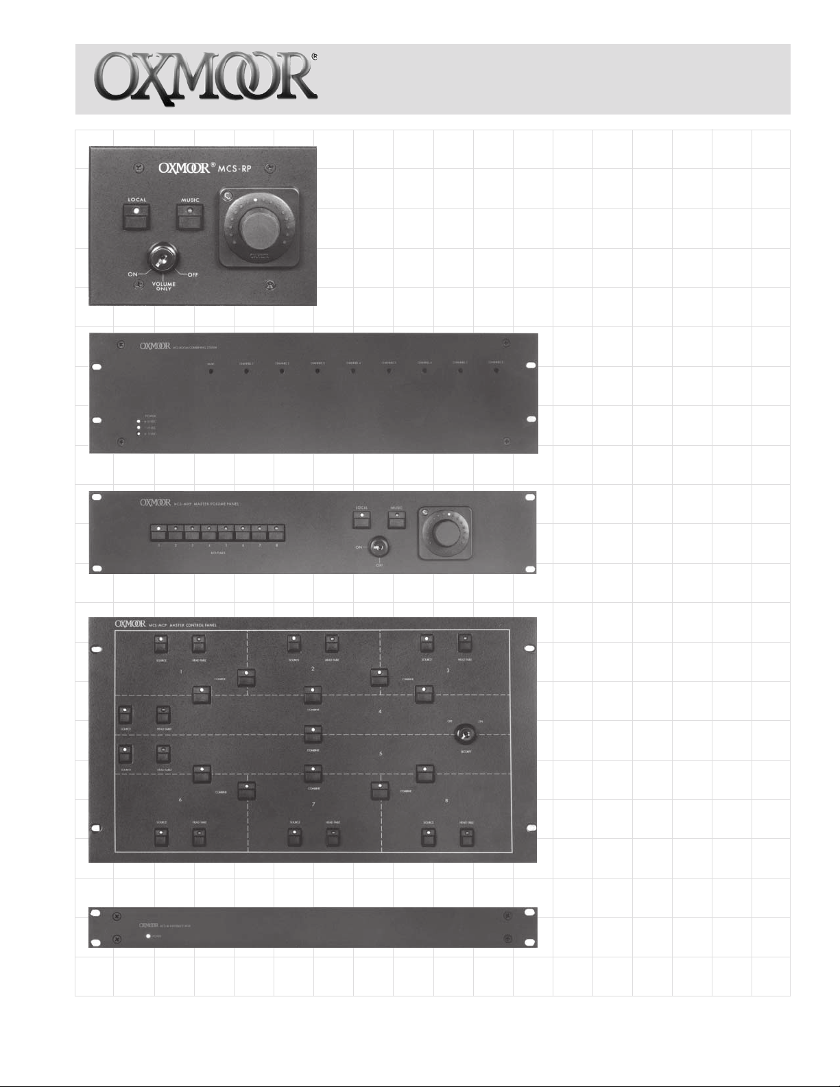
ROOM PANEL
•Room volume control, local source and
background music select switches
•Synchronizes with other Room Panels when
rooms are combined
•PA-422 communication interface
•Non-volatile memory
•Combine any combination of eight
rooms
MAINFRAME
MASTER VOLUME PANEL
•Volume control and source selection
for each room at a remote location
TYPICAL
MASTER CONTROL PANEL
•Custom screened for your
specific room configuration
•Combine, source and head-table
switches for each zone
•Field-programmable
•PA-422 communication interface
INTERFACE BOX
•Converts combine, source and
head-table switch closures to PA422 signals that can communicate
with the Mainframe
Now it’s easy to combine rooms in ways they
once said couldn’t be done. And while you get all
the control flexibility you’ve dreamed of, user
operation is incredibly simple and intuitive. In
fact, the MCS Room Combining System lets you
combine the audio and synchronize the local
volume controls of any combination of eight
rooms; up to eleven different possibilities — even
if they are not adjacent.
The power behind all of this control flexibility
lies in the MCS System’s on-board
microprocessor systems — powerful, yet easily
field programmable to virtually any combining
configuration.
Power and simplicity are there in every user
function as well. Oxmoor’s custom-screened
Master Control Panel shows the floor plan of the
rooms that may be combined. Combine, Source
and Head-Table switches are intelligently
positioned to indicate their functions at a glance.
For each room, MCS-RP Room Panels feature our
innovative RC-16 Volume Control and its unique
“Virtual PointerTM” LED. Simple push switches
allow selection of a local sound source (such as a
mixer), background music or neither. And since
volume settings for a local source and
background music are apt to be different, the last
volume setting of each is stored in memory and
recalled when switching between the two.
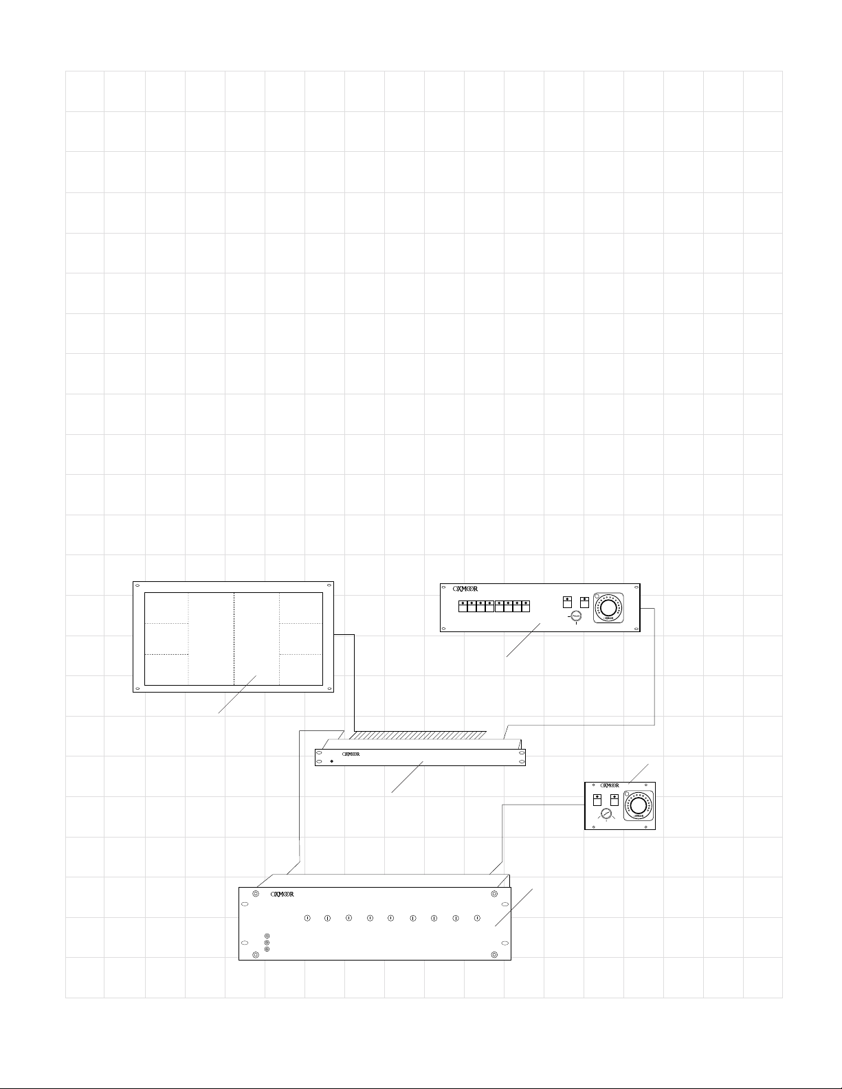
While easy to operate, the MCS System simplifies
system design and installation as well. MCS
control components communicate with each
other using PA-422 protocol, allowing lengthy
cable runs, easy installation and a minimum
number of conductors. Master control of the MCS
System may come from Oxmoor’s Master Control
Panel or another PA-422 controller. An MCS-IB
Interface Box can be used to allow control by
contact closures, converting them to PA-422
signals.
Just as important as ease of operation is effective
system security. Tampering with the MCS System
is prevented by key switches at the Master
Control, Master Volume and Room Panels. And
in the event of a power failure, a non-volatile
memory will preserve system settings.
1
2
3
4567
Master Control Panel
POWER
+15 VDC
–15 VDC
+ 5 VDC
8
MCS ROOM COMBINING SYSTEM
MUSIC CHANNEL 1
MCS -IB INTERFACE B OX
POWER
MCS-IB
Interface Box
CHANNEL 2 CHANNEL 3
CHANNEL 4
12
Master Volume Panel
CHANNEL 5
CHANNEL 6 CHANNEL 7 CHANNEL 8
MCS – MVP Master Volume Panel
45678
3
ROOMS
LOCAL
ON
OFF
Mainframe
MUSIC
Room Panel
MCS–RP
LOCAL
MUSIC
OFFON
VOLUME
ONLY
MCS ROOM COMBINING SYSTEM
Page 2

MCS SYSTEM COMPONENTS
MASTER CONTROL PANEL
The 6 rack-unit (10.50") MCS-MCP Master
Control Panel, custom-designed for your specific
configuration, is the primary user interface to the
system.
MASTER VOLUME PANEL
A 2 rack-unit (3.50") MCS-MVP Master Volume
Panel provides volume control and source
selection functions for each room at a remote
location.
INTERFACE BOX
The 1 rack-unit (1.75") MCS-IB Interface Box
provides the interface between a control device
using contact-closures, such as the MCS-MCP
Master Control Panel, and the MAINFRAME.
ROOM PANEL
The 3 gang MCS-RP Room Panel provides a
means to adjust local volume and to assign either
a local source or a background music source to
the room.
MAINFRAME
This 3 rack-unit (5.25") chassis houses a power
supply plus three types of plug-in cards. These
include MCS-LI Line Input card for each room to
be combined, a MCS-LC Logic Card, and one
MCS-CC Control Card.
MAINFRAME
MODULES
MCS-L I
MCS-LC Logic Card
When rooms are combined, all
volume controls in the
combined rooms default to a
preset level. The preset levels
may be set using the COMBINE
LEVEL LOCAL and MUSIC
attenuators on the MCS-LC
Logic Card.
Also included on the Logic
Card is a balanced MUSIC
input that can be used for
background music sources and
paging. A volume control,
accessible from the front panel,
allows level adjustment of this
input.
The Logic Card provides PAGE
logic connections for paging
overrides. Rooms which have
MUSIC selected on their Room
Panel will default to the MUSIC
preset level when the PAGE
logic is used.
Also on the Logic Card, screw
terminal blocks provide HEADTABLE switching logic for relay
muting of speakers over a head
table location.
MCS-LC
MUSIC IN +
MUSIC IN -
SHIELD
PAGE
COM
COM
HEAD 1
HEAD 2
HEAD 3
HEAD 4
HEAD 5
HEAD 6
HEAD 7
HEAD 8
POWER
COM.
MCS–LC
Logic Card
MCS-CC
COMBINE LEVEL
LOCAL
MUSIC
MCS-LI Line Input Card
An MCS-LI Line Input Card is
used for each zone or room to
be combined. The Line Input
card provides barrier strips for
balanced audio inputs and
outputs, remote volume
control, and LOCAL and
MUSIC SELECT with TALLY
indications. A trim pot,
accessible from the front panel,
may be used for audio input
level adjustment.
MCS–LI Line Input Card
IN +
IN –
SHIELD
OUT +
OUT -
SHIELD
COM
CU
CD
DISP
LOCAL TALLY
MUSIC TALLY
LOCAL SELECT
MUSIC SELECT
MUTE
MCS-CC Control Card
Communication between a
controller and the MCS-LC
Logic Card in the system
Mainframe follows PA-422
protocol. The MCS-CC Control
Card provides loop-through
connections and address
selection for PA-422 devices.
MCS–CC Control Card
Page 3
PA-422
IN
PA-422
OUT
PA-422
ADDRESS
1
2
4
8
16
32
64
128
ON

MCS-MCP MASTER CONTROL PANEL
Oxmoor’s custom Master Control Panel is
designed to be a user interface to the MCS
System. Thanks to the panel’s highly intuitive
layout, even an unskilled operator can see at a
glance how to operate the MCS system. Its
simplicity results in less time spent in training,
retraining and costly call-backs.
The Master Control Panel presents the user with a
graphic representation of the layout of the rooms
which may be combined. The position of each
switch on this “floor plan” tells the operator
exactly which room or rooms will be affected by
its activation. Each push-button switch includes
an LED TALLY indicator to display its current
status.
There are three types of functions that may be
performed at the Master Control panel:
1. Room combining
2. Source selection
3. Head-table speaker muting
A key switch allows the user to secure all Master
Control Panel functions, preventing unauthorized
personnel from tampering with system settings.
COMBINE Button
The position of each switch on the Master Control
Panel’s room map makes system operation highly
intuitive. To COMBINE two rooms, for example,
the operator simply pushes a button marked
COMBINE that lies at the intersection of the two
rooms. This combines the inputs of the selected
room’s amplifiers and causes all MCS-RP Room
Panels in the combined rooms to be
synchronized.
SOURCE Button
Each room on the Master Control Panel may also
include a SOURCE button. Combining two or
more rooms causes the audio SOURCE in each
room to default to LOCAL (usually a mixer) and
the LOCAL SOURCE to become “active”, or
added to the potential overall mix. Sources may
be deleted or added again with the SOURCE
button. With each push, the SOURCE button
“toggles” between on (source available) and off
(source disconnected). An LED on each button
illuminates to show its status.
The SOURCE function may be used to increase
the number of available inputs or to allow access
to inputs at a variety of locations within the
combined rooms. Unused sources may be
switched off to avoid any chance of accidental
interference.
HEAD-TABLE
HEAD-TABLE
HEAD-TABLE
TYPICAL MCS–MCP MASTER CONTROL PANEL SECTION
SOURCE
BERKSHIRE ROOM
COMBINE
SOURCE
WYNFREY BALLROOM
COMBINE
COMBINE
SOURCE
RIVERCHASE BALLROOM
ON
OFF
HEAD-TABLE Button
A HEAD-TABLE switch may be present in each
room on the panel layout. This button provides
the means for switching logic to control external
circuits for muting speakers over a head-table
location in the room indicated. The HEADTABLE switch controls open-collector outputs for
driving relays, provided by others. Each push of
the button toggles the outputs between an on and
off state. An LED on the HEAD-TABLE switch
displays its status.
Page 4

MCS-RP ROOM PANEL
A typical MCS system includes a wall-mounted MCS-RP Room Panel in each room or zone to be
combined. The rotary volume control is Oxmoor’s well-established RC-16, which features a unique
“Virtual Pointer
LOCAL sound source (usually a mixer) or OFF. And since volume settings for a local source and
background music are apt to be different, the last volume setting of each is stored in memory and recalled
when switching between the two. When rooms are combined, all functions on their Room Panels become
synchronized.
A lockable key switch on the MCS-RP Room Panel offers three levels of user-selectable security over the
panel’s functions. All three panel controls may be used when the switch is in the ON position. When
locked in the VOLUME ONLY position, the volume control is operable; the LOCAL and MUSIC select
switches are secured. The OFF position secures all panel controls against unauthorized tampering.
TM
” LED array. Push-button switches allow the user to select background MUSIC,
MCS–RP ROOM PANEL
LOCAL
MCS–RP
MUSIC
VOLUME
OFFON
ONLY
MCS-MVP MASTER VOLUME PANEL
Designed to be located near the Master Control Panel, the rack-mounted MCS-MVP Master Volume
Panel provides synchronized remote control of any MCS-RP Room Panel. A key switch makes panel
security simple.
MCS–MVP
MASTER VOLUME
PANEL
12
MCS–MVP Master Volume Panel
45678
3
ROOMS
LOCAL
ON
MUSIC
OFF
MCS-IB INTERFACE BOX
Any MCS system which utilizes contact-closure controls and/or uses an Oxmoor Master Volume Panel
requires an Interface Box. The Master Control Panel includes the Interface Box as an integral part of its
assembly.
Oxmoor’s MCS-IB Interface Box serves as an interpreter to convert contact closures to PA-422 signals that
can communicate with the MCS Mainframe. Screw terminal blocks are provided for COMBINE,
SOURCE, and HEAD-TABLE lines, LED TALLY indicators and security switching.
1T
2T3T4T 5T 6T 7T 8T 9T 10 T11 T
LINKS
1T
2T
4T 5T 6T 7T 8T
1T
2T
SOURCE HEAD TABLE
3T
MCS–IB INTERFACE BOX REAR VIEW
Page 5
3T
4T 5T 6T 7T 8T
COM
V+
LOCK
PA-422 OUTPUT PA-422 INPUT
MVP I/F
12V DC
COM
+

MCS SYSTEM SPECIFICATIONS
AUDIO IN Type ................................................. Electronically Balanced (RF Suppressed)
Connectors ....................................... Screw Terminal Blocks
Input Impedance ............................... 80 k Ohms
Maximum Input Level ....................... +24 dBu
AUDIO OUT Type ................................................. Electronically Balanced
Connectors ....................................... Screw Terminal Blocks
Source Impedance ............................ 20 Ohms (10 Ohms Each Side)
Maximum Output Level
(Ref. 1 kHz @ rated THD)
Terminated w/600 Ohms .................. +18 dBm
Unterminated ................................... +26 dBu
FREQUENCY RESPONSE 20 Hz to 20 kHz ............................... +0, -0.3 dB
-3 dB Points, Ref. 1 kHz .................... 4 Hz to 70 kHz (+4 dBm Output)
HUM AND NOISE Ref. +4 dBm Output @ Unity Gain ...... -85 dB (20 Hz to 20 kHz, Unweighted)
DISTORTION Total Harmonic (THD + NOISE)
Ref. +4 dBm Output @ Unity Gain ...... -80 dB/0.01% (20 Hz to 20 kHz)
Ref. +4 dBm Output @ Unity Gain:
SMPTE IMD ............................... -80 dB/0.01%
Transient IMD ........................... -80 dB/0.01%
CROSSTALK & OFF ISOLATION Channel to Channel .......................... -85 dB (@ 1 kHz)
Driven Input to Off Output ................. -85 dB (@ 1 kHz)
TRIM POT GAIN RANGE Ref. 0 dBu Output ............................. ±15 dB
VOLUME CONTROL Type ................................................. Oxmoor's RC-16
Connector ........................................ Screw Terminal Blocks
LOGIC Connector ........................................ Screw Terminal Blocks
Input Type ........................................ Active Low, Internally Pulled Up
Input Protection ................................ 1/2 Max. Line Voltage, 12 kV Static
Logic Action ...................................... Momentary Closure to Common
Logic Levels (at Terminal Block) ....... Low < .8 Volts, High > 2.4 Volts
Maximum Sink Current ..................... 1 mA
Maximum Cable Length .................... 600m (2000 ft), #22 AWG
TALLY Connector ........................................ Screw Terminal Blocks
Output Type ...................................... Open-Collector Darlington to Common
Max. Sink Current ........................... 500 mA
Max. Voltage .................................... 50 VDC
Specifications subject to change without notice.
Printed 7/01
Oxmoor Corporation, LLC, 309 Cahaba Valley Parkway, Birmingham, AL 35124 USA Toll Free: 1-800-262-6898
Phone: 205-982-8200 Fax: 205-982-8250 E-mail: info@oxmoor.com Internet: www.oxmoor.com
 Loading...