

DEQ-I™ & DEQ-II
HIGH-RESOLUTION
PROGRAMMABLE EQUALIZERS
™
Installation
&
Operation
Manual

TABLE OF CONTENTS
DEQ-I & DEQ-II INTRODUCTION ...................................................................................................... 1
DEQ-I & DEQ-II QUICK REFERENCE ................................................................................................. 1
DEQ-I QUICK REFERENCE .............................................................................................................. 2
DEQ-II QUICK REFERENCE ............................................................................................................. 3
DEQ-II QUICK REFERENCE (CONTINUED) ....................................................................................... 4
DEQ-II QUICK REFERENCE (CONTINUED) ....................................................................................... 5
DEQ-II QUICK START TUTORIAL ...................................................................................................... 6
DEQ-II QUICK START TUTORIAL (CONTINUED)................................................................................ 7
DEQ-II QUICK START TUTORIAL (CONTINUED)................................................................................ 8
DEQ-II EQUALIZE MENU ................................................................................................................. 9
DEQ-II EQUALIZE MENU (CONTINUED) .......................................................................................... 10
DEQ-II EQUALIZE MENU (CONTINUED) .......................................................................................... 11
DEQ-II EDIT MENU......................................................................................................................... 12
DEQ-II EDIT MENU (CONTINUED) .................................................................................................. 13
DEQ-II UTILITY MENU .................................................................................................................... 14
DEQ-II UTILITY MENU (CONTINUED) ............................................................................................. 15
DEQ-II UTILITY MENU (CONTINUED) ............................................................................................. 16
SYSTEM SECURITY ....................................................................................................................... 17
DEQ-I & II MULTI-UNIT SYSTEM ..................................................................................................... 18
DEQ-I & DEQ-II MULTI-UNIT SYSTEM (CONTINUED) ....................................................................... 19
DEQ-I & DEQ-II MULTI-UNIT SYSTEM (CONTINUED) ....................................................................... 20
DEQ-I & DEQ-II MULTI-UNIT SYSTEM (CONTINUED) ....................................................................... 21
DEQ-I INTERNAL CONTROLS .........................................................................................................22
DEQ-I INTERNAL CONTROLS (CONTINUED) ................................................................................... 23
APPENDIX A: HARDWARE INTERCONNECTION DETAILS ................................................................ 24
APPENDIX B: ERROR MESSAGES ................................................................................................... 25
APPENDIX C: CHARACTER SET ...................................................................................................... 25
APPENDIX D: GLOSSARY ............................................................................................................... 26
APPENDIX E: DEQ-I DISPLAY CODES ............................................................................................. 27
APPENDIX F: PRESET SELECT TALLY ............................................................................................. 28
INSTALLATION & SET-UP NOTES ................................................................................................... 29
INSTALLATION & SET-UP NOTES...................................................................................................30
DEQ-I & DEQ-II SPECIFICATIONS ...................................................................................................31
OXMOOR FACTORY SERVICE ......................................................................................................... 32
OXMOOR TWO YEAR LIMITED WARRANTY ..................................................................................... 32
CONTACT OXMOOR ....................................................................................................................... 32

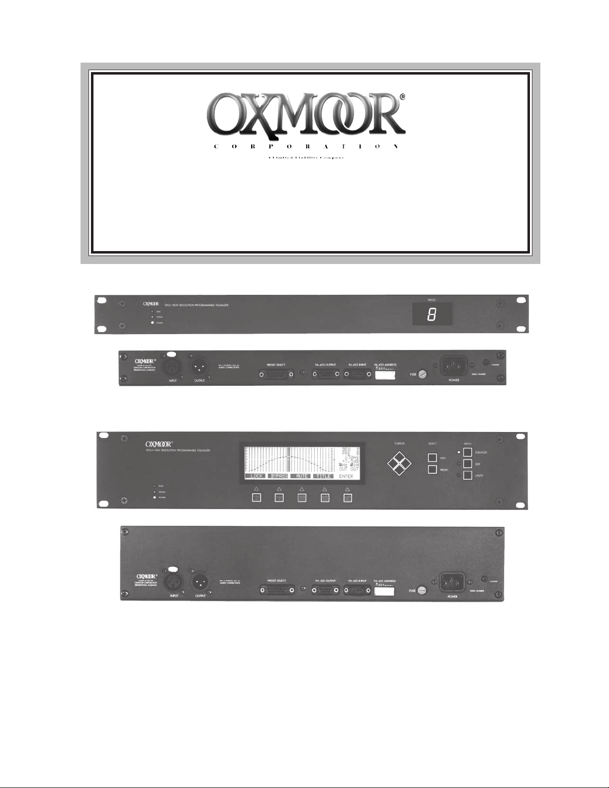
DEQ-I & DEQ-II INTRODUCTION
There are two versions of the DEQ equalizer.
The DEQ-II is a two rack-space device. Its sophisticated
control panel includes a number of buttons for parameter
entry and a large LCD display that provides setting and
status information. The single-channel, 29-band DEQ-II
offers 1/3–octave filters and second–order high-pass and
low-pass filters, selectable on 1/6–octave frequency spacings. Filter settings are stored in any of eight nonvolatile,
programmable memories called PRESETS. The contents
of a PRESET can be modified by either the DEQ-II’s own
control panel, or by a remote controlling device, such as
DEQ-I & DEQ-II QUICK REFERENCE
TERMS USED
PRESET: One of the 8 groups of settings that completely
configure the equalizer and defines how it will process
audio.
PRESET PORT: A 15–pin D-sub connector on the back
panel through which Presets may be selected.
COMMUNICATIONS PORT: The 9–pin D-sub (INPUTmale), (OUTPUT-female) PA-422 connectors on the back
panel that are used for serial communication with other
equalizers, a PC or another PA-422 control device.
an IBM compatible, Macintosh, or another DEQ-II.
Once a PRESET has been set, it can be locked to prevent tampering.
Like the DEQ-II, the DEQ-I is a single-channel, 29-band,
1/3-octave graphic EQ with 2nd-order high-pass and
low-pass filters. Filter settings are stored in 8 programmable PRESETS. The DEQ-I is a one rack-space device
without a control panel. Programming is accomplished
either through the DEQ-I’s COMMUNICATIONS
PORT (using a PC, a DEQ-II or some other PA-422 control device) or through the DEQ-I’s internal controls.
EQUALIZATION CURVE (or simply, CURVE): A term
describing the collection of filter settings (bandpass,
high-pass, and low-pass) that completely define how
the equalizer will process audio. (See PRESET at left.)
ACTIVE PRESET: The Preset that currently has control of the audio.
ACTIVE FILTER BAND: The filter band which is currently addressed by the cursor and for which the slider
may be adjusted.
HARDKEYS: Those buttons on the front panel of the
DEQ-II whose functions are constant. Hardkeys have
labels screened on the front panel.
SOFTKEYS: The buttons on the front panel of the DEQ-II
whose functions change depending on the menu.
STATUS AREA: The portion of the LCD display dedicated
to displaying the present state of equalizer function.
CURVE AREA: The portion of the LCD display dedicated
to displaying the “Active Preset” curve.
SOFTKEY/MESSAGE AREA: The portion of the LCD display dedicated to displaying the Softkey labels and messages. This area also displays DEQ TITLE and PRESET
name information.
LOGGING ON: Term which describes the act of gaining control of a DEQ-II through its front panel; accomplished by selecting a Main Menu key and (possibly)
giving a Password.
LAST EQUALIZER RECALL: Function similar to “last
channel recall” of a television remote control; switches
between last two active equalizers.
ADDRESS SELECTOR: An 8-position dip-switch
which sets the PA-422 address of the equalizer. Note:
This address must be unique for each equalizer in the system.
BAND CURSOR: A solid “bar” that overlaps the slider
“slot” of the “Active Filter Band;” denotes the Active
Filter Band.
Page 1

DEQ-I DESCRIPTION
(Callouts refer to Figures 1.0 and 1.1)
DEQ-I QUICK REFERENCE
1. POWER on LED is illuminated when the unit is on.
2. SIGNAL-presence LED is illuminated when a signal
above -40 dBu is present at the unit's output.
3. PEAK LED is illuminated when an output level of 17
dBu is reached.
4. LED DISPLAY - A seven-segment LED Display that
displays the active Preset number.
5. INPUT CONNECTOR - XLR input, Pin 2 positive,
accepts balanced or unbalanced signals from line-level
audio devices.
6. OUTPUT CONNECTOR - XLR output, pin 2 positive, accommodates balanced or unbalanced lines.
7. PRESET SELECT - Female, 15–pin D-sub connector.
Provides for connection of external switches for remote
Preset selection. Momentary contact closures required.
8. PA-422 OUT - Female, 9–pin D-sub connector. It is
used to carry the PA-422 data to the next equalizer's PA422 IN or to another PA-422 device.
9. PA-422 IN - Male, 9–pin D-sub connector. This port is
connected to the PA-422 OUT of another equalizer, a Personal Computer, or a controller with PA-422 output.
10. PA-422 ADDRESS - A selector switch that is used to
assign an address to the equalizer when connecting two
or more equalizers together to form a network.
11. FUSE HOLDER - Replace only with approved type
of fuse in a rating appropriate to the mains voltage, as
indicated on back panel. (See SPECIFICATIONS).
12. POWER CONNECTOR - Standard IEC 3-pin connector for AC power cord. Use only with grounded (3wire) outlets. Cord sets are available for all world connection standards.
13. CHASSIS GROUND - A screw with a star washer
enables the installer to secure a ground wire to the
chassis.
3
2
1
OXMOOR
MADE IN USA BY
OXMOOR CORPORATION
BIRMINGHAM, ALABAMA
PUSH
INPUT
5
DEQ-I HIGH RESOLUTION PROGRAMMABLE EQUALIZER
PEAK
SIGNAL
POWER
STATUS LEDs
Figure 1.0: Front Panel View of DEQ-I
AUDIO CONNECTORS
OUTPUT
6
PRESET SELECTPIN 2 POSITIVE ON ALL
7
Figure 1.1:
Rear Panel View of DEQ-I
PA-422 OUTPUT
8 9
PA-422 INPUT
PA-422 ADDRESS
128643216842
ON
1
10 11
PRESET
4
FUSE
POWER
12
CHASSIS
SERIAL NUMBER
13
Page 2

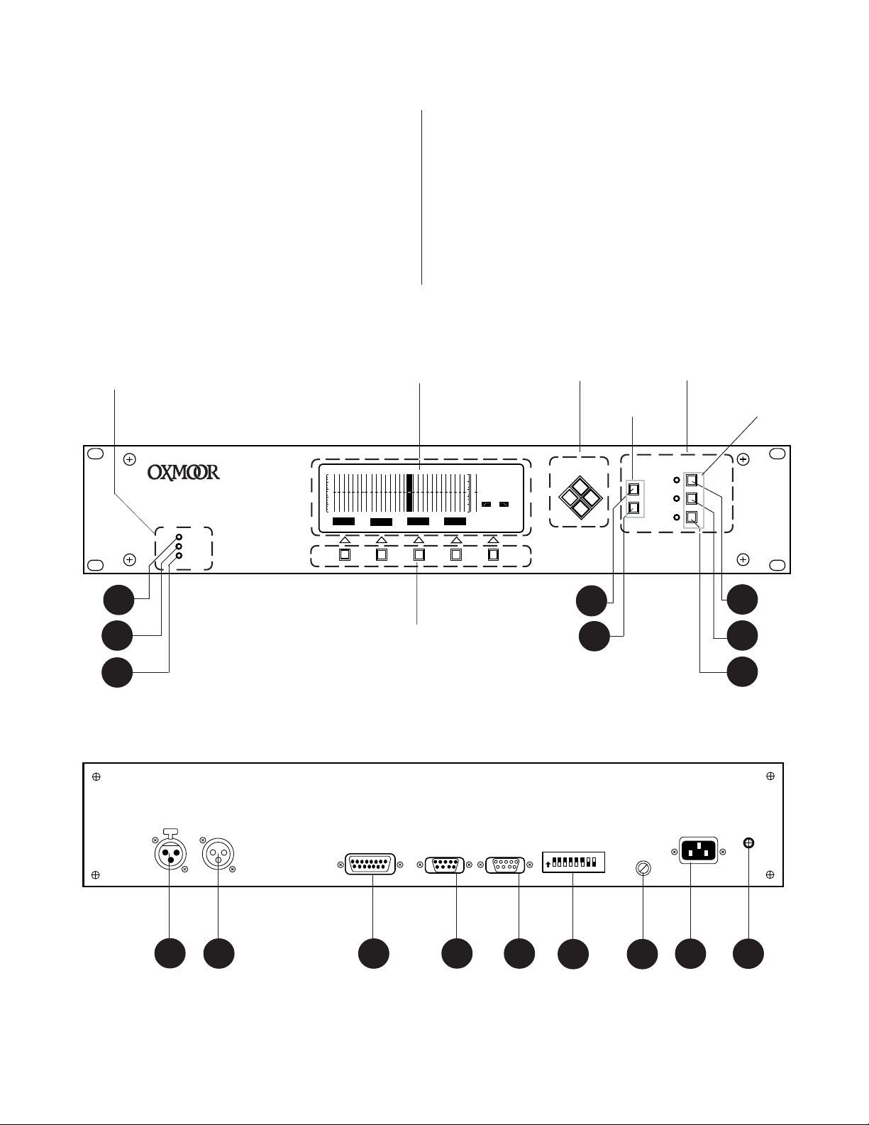
DEQ-II DESCRIPTION
(Callouts refer to Figures 1.2 and 1.3)
DEQ-II QUICK REFERENCE
SIGNAL STATUS LEDs:
1. POWER on LED is illuminated when the unit
is on.
2. SIGNAL-PRESENCE LED is illuminated
when a signal above -40 dBu is present at the
unit's output.
3. PEAK LED is illuminated when an output
level of 17 dBu is reached.
LCD DISPLAY - A large backlit display that gives a
graphic representation of the active curve and immediate information on the status of the equalizer. The
LCD display also defines the functions that the
Softkeys perform.
CURSOR KEYS - Buttons which are used for selecting
and adjusting values and editing text.
SELECT BUTTONS:
7. EDIT - This menu allows:
Logging on to the equalizer
Copying and Pasting of equalization curves
Clearing equalization curves stored in Presets
Naming the Presets
Locking and Unlocking Presets
Bypassing and inserting the Equalizer
Setting Preset Titles
8. UTILITY - This menu allows:
Logging on to the equalizer
Logging Off (terminating an equalization session)
Setting Passwords
Adjusting the contrast of the display
Turning off the display light
Naming the equalizer
SOFTKEYS - These buttons are used to select an action available when you are in EQUALIZE, EDIT, or
UTILITY mode. The function each Softkey performs
may change depending on which menu has been accessed.
4. DEQ - Accesses the DEQ select menu. In this
mode, select the desired equalizer using the Cursor keys.
5. PRESET - Accesses the Preset mode. In this
mode you can select the desired Preset by using
the Cursor keys. Use the UP and DOWN Cursor
keys to select one of eight Presets.
HARDKEYS - These buttons perform dedicated functions as labeled on the front panel.
MENU Buttons - There are three menus which control
all functions. Selection of each is confirmed by the illumination of an adjacent LED.
6. EQUALIZE - This menu allows:
Logging on to the equalizer
Adjusting filter settings
Adjusting High- and Low-pass Filters
Adjusting equalizer gain
BACK PANEL FEATURES:
9. INPUT CONNECTOR - Female, XLR connector,
pin 2 positive, accepts balanced or unbalanced
signals from line-level devices.
10. OUTPUT CONNECTOR - Male, XLR connector,
pin 2 positive, accommodates balanced or unbalanced lines.
11. PRESET SELECT - Female, 15–pin D-sub connector. Provides for connection of external
switches for remote Preset selection. Momentary
contact closures required.
12. PA-422 OUT - Female, 9–pin D-sub connector. It
is used to carry the PA-422 data to the next
equalizer's PA-422 IN or to another PA-422 device.
13. PA-422 IN -Male, 9–pin D-sub connector. This
port is connected to the PA-422 OUT of another
equalizer, a Personal Computer, or a controller
with PA-422 output.
Page 3
DEQ-II QUICK REFERENCE (CONTINUED)
14. PA-422 ADDRESS -A selector switch that is
used to assign an address to the equalizer when
connecting two or more equalizers together to
form a network.
15. FUSE HOLDER - Replace only with approved
type of fuse in a rating appropriate to the mains
voltage, as indicated on back panel. (See SPECIFI-
CATIONS).
SIGNAL STATUS
®
DEQ-II High Resolution Programmable Equalizer
BYPASS
PEAK
SIGNAL
POWER
LCD DISPLAY
MUTE TITLELOCK
16. POWER CONNECTOR - Standard IEC 3-pin
connector for AC power cord. Use only with
grounded (3-wire) outlets. Cord sets are available for all world connection standards.
17. CHASSIS GROUND POST - A screw with a
star washer enables the installer to secure a
ground wire to the chassis.
CURSOR KEYS
SELECT
BUTTONS
DEQ
1
PRE
1
1 kHz
0 dB
OUT
OUT
ENTER
CURSOR SELECT MENU
HARD KEYS
DEQ
PRESET
MENU
BUTTONS
EQUALIZE
EDIT
UTILITY
3
2
1
OXMOOR
MADE IN USA BY
OXMOOR CORPORATION
BIRMINGHAM, ALABAMA
PUSH
INPUT
9
OUTPUT
10
AUDIO CONNECTORS
SOFTKEYS
Figure 1.2: Front Panel View of DEQ-II
PRESET SELECTPIN 2 POSITIVE ON ALL
11
PA-422 OUTPUT
12
PA-422 INPUT
13
Figure 1.3: Rear Panel View of DEQ-II
PA-422 ADDRESS
128643216842
ON
14
4
5
6
7
8
CHASSIS
1
FUSE
POWER
15
SERIAL NUMBER
1716
Page 4

DEQ-II QUICK REFERENCE (CONTINUED)
SOFTKEY &
MESSAGE AREAS
DEQ-II LCD DISPLAY LAYOUT
(Callouts refer to Figure 1.4)
1
CURVE AREA
2
BYPASS
Figure 1.4: LCD LAYOUT
MUTE TITLELOCK
STATUS AREA
3
OUT
ENTER
DEQ
PRE
25 Hz
0 dB
OUT
6
5
4
1
8
8
9
7
The LCD display information is organized into three
main sections, as shown in Figure 1.4. These sections
are: The Softkey/Message Area , the Curve Area, and
the Status Area.
SOFTKEY/MESSAGE AREA: This area is used to label the Softkeys (i.e., identify the Softkey functions)
and to display messages, such as error announcements. The Softkey/Message Area is also used, depending on the action being performed, to display and
allow editing of the Name, Title, or Passwords of the
equalizer.
THE CURVE AREA: Gives a quick graphical view of
the filter settings for the Active Preset. While the
graduations allow an estimation of the actual setting
for any given band, the Status Area will display the
exact setting.
1. Each "slug" represents a Bandpass Filter setting. The Bandpass Filters may be adjusted in
1/2 dB steps over a ±12 dB range.
2. This is the Band Cursor, a solid "bar" that
overlaps the slider "slot" of the "Active Filter
Band." It denotes the Active Filter Band.
3. This area represents the output gain slider.
Adjustable in 1/2 dB steps over ±12 dB range.
STATUS AREA: Provides information about the current operational state of the equalizer. In particular:
4. Displays the number (address) of the Active
equalizer. This is the equalizer with which the
controlling DEQ-II is currently communicating.
5. Displays the number of the active Preset.
6. Displays the center frequency of the Active
Bandpass Filter.
7. Displays the setting of the Active Bandpass
Filter, or Gain control.
8. Displays the setting of the Low-Pass Filter.
9. Displays the setting of the High-Pass filter.
NOTE: Back-light will time out; see page 18.
Page 5
DEQ-II QUICK START TUTORIAL
CAUTION: If you set a Password, you must use it
to address the DEQ. It is best not to set a Password
until your equalization session is over.
This section allows a first-time user to quickly and
efficiently begin using the basic (and more frequently
used) functions of the equalizer. The procedure described below assumes that you have just one DEQII, and that it has not been programmed or modified
since it left the factory. This ensures that none of the
Presets have been Locked and no Passwords have
been set. Locking Presets and setting Passwords are
advanced topics that are covered in detail in later
chapters.
TURNING ON THE EQUALIZER
Apply power to the unit. There is no on/off switch;
simply plug the equalizer in. After a few seconds,
the Oxmoor logo will be displayed. Several seconds
later, the Oxmoor logo will be replaced by the Active
Preset curve, which will have (if the equalizer has
not already been adjusted) all sliders set to 0 dB. The
DEQ address (shown in line 1 of the Status Area)
should be 1, and the Preset number (shown in line 2
of the Status Area) should be 1. The bottom line of
the display (i.e., the Softkey/Message Area) should
be displaying: PRESET:
Since this preset currently has no Title, Figure 1.5
shows the LCD display as it should appear at this
point. Note that none of the Main Menu LED indicators are lit. This is because you are not “logged on”
to the unit.
DEQ
1
PRE
1
1 kHz
0 dB
OUT
OUT
LE
ENTER
CURSOR SELECT MENU
DEQ
PRESET
EQUALIZE
EDIT
UTILITY
Figure 1.6: Main Menu Buttons
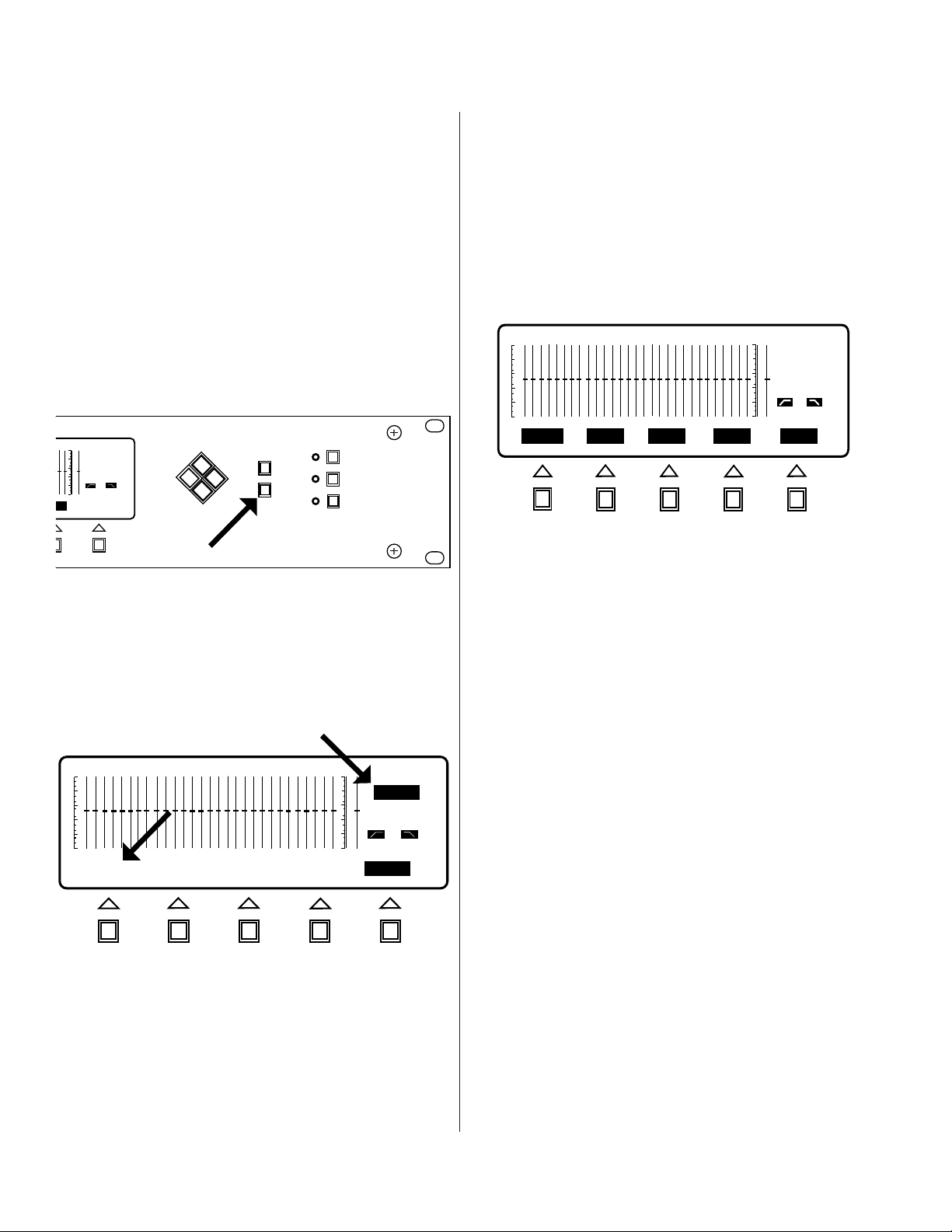
Figure 1.7 shows what the display should now look like.
Notice that the Softkey/Message Area now displays a
number of labels above the Softkey buttons. Each label
defines the function that the Softkey performs. If a label is
in reverse-video it indicates that the softkey under that
label can be used at this time. Normal-video labels indicate
functions that are currently unavailable (but may be
available later in the session, depending on the action
performed). At this point, the labels LOCK, BYPASS,
MUTE, and TITLE are all in reverse-video and ENTER is
in normal-video. Also, note that the 25 Hz bandpass filter
slider is now in reverse-video and the Status Area has
been updated to give the bandpass filter information. A
1
DEQ
8
PRE
25 Hz
0 dB
OUT
OUT
BYPASS
MUTE TITLELOCK
ENTER
DEQ 0
PRE 1
OUT OUT
PRESET:
Figure 1.5: Start-Up Screen
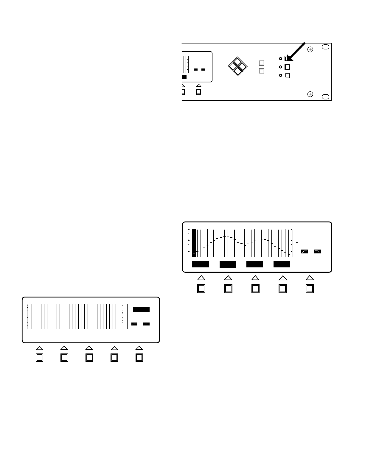
LOGGING ON TO THE EQUALIZER
To log on to the equalizer, press any one of the three
Main Menu buttons, (see Figure 1.6). Any one of the
Main Menu buttons will log you on to the equalizer,
but for this exercise, press the Equalize Menu button.
If you inadvertently pushed the EDIT or UTILITY
buttons, that’s OK. Simply push the Equalize button.
Figure 1.7: Equalize Menu Screen
slider in reverse-video, called the “Band Cursor”, indicates
the Active Filter Band, that is, the band that can currently
be adjusted. You are now logged on and may begin using
the equalizer. Note: The Preset Select connector on the
rear of the DEQ is disabled when you are "logged on.”
CHANGING MENUS
Before describing how to change the filter settings let's
become a little more familiar with the menus. You should
currently be in the EQUALIZE menu (the Equalize Menu
LED indicator should be on). Now, change to the EDIT
menu by pressing the EDIT menu key (see Figure 1.8).
Notice that the Softkey/Message Area has been changed
so that the menu options available in this menu are
displayed.
(Continued on next page)
Page 6
DEQ-II QUICK START TUTORIAL (CONTINUED)
DEQ
1
1
PRE
OUT
OUT
PASTE
CLEAR TITLECOPY
ENTER
Figure 1.8: Edit Menu Screen
Also note that the LED indicator beside the Menu key
you pushed is now lit, and the EQUALIZE Menu key
indicator is no longer lit.
Finally, note that none of the filter sliders are now in
reverse-video, and the sections of the Status Area which
give frequency and setting information have been erased.
This denotes that there is no Active Filter Band, hence,
no band may be adjusted. Filter sliders (and high-pass
and low-pass filters) may be adjusted only while in the
EQUALIZE menu.
Now, change to the UTILITY menu by pressing the
UTILITY menu key (see Figure 1.9). Notice that the only
changes are that the appropriate Menu indicator is now
lit and the Softkeys have been relabeled. Finally, go back
to the EQUALIZE menu by pressing the EQUALIZE
menu key. Once in EQUALIZE, you may begin adjusting
the sliders.
Filter Band frequency and slider position) has been
updated to reflect this change. Continue pushing the
UP and DOWN cursor keys to adjust the slider until
you are comfortable with the action of the keys and the
repeat rate. Notice that each time the UP or DOWN
cursor key is pressed, the Status Area is updated. Now,
let's change the slider settings in some other bands.
CHANGING THE ACTIVE FILTER BAND
To make another frequency band become the Active
Filter Band, press the RIGHT cursor key. Observe that
the Band Cursor has moved one position to the right,
and that the Status Area has been updated. Push the
RIGHT button several more times. Now push the
LEFT cursor key and notice that the Band Cursor has
moved back one position to the left. Each time the
LEFT or RIGHT cursor key is pressed the Band Cursor
moves and the Status Area is updated. Continue to use
the LEFT and RIGHT cursor keys to change the Active
Filter Band and make slider adjustments using the UP
and DOWN keys until you feel familiar with the
function. Now, move the Band Cursor until it rests on
the 16 kHz frequency band. Push the RIGHT cursor
key one time and notice that the Band Cursor has
skipped over the right graduation and now rests on
the GAIN band. The Gain slider may be adjusted exactly
like the bandpass filter sliders. Now, press the LEFT
cursor key once and notice that the Band Cursor again
rests on the 16 kHz band. Finally, push the RIGHT
cursor key one more time so that the Band Cursor
again rests on the GAIN band. We may now learn how
to adjust the high-pass and low-pass filters.
DEQ 1
PRE 1
OUT
OUT
LOG OUT
PASSWRD
DISPLAY NAME
ENTER
Figure 1.9: Utility Menu Screen
ADJUSTING THE SLIDERS
While in the EQUALIZE menu, it is possible to adjust
the slider position. To adjust the active slider (the slider
that is in reverse-video) push the UP or DOWN cursor
key. Notice that each push of the button changes the
level in 0.5 dB increments. If the button is held, it will
begin to repeat just like a computer's keyboard.
Notice that the slug in the Active Filter Band has moved,
and that the band information in the Status Area (Active
ADJUSTING HIGH-PASS & LOW-PASS FILTERS
The high- and low-pass filters are accessed just like the
bandpass filter bands, by using the LEFT and RIGHT
cursor keys to move the Band Cursor to the desired
band. With the Band Cursor resting on the GAIN band,
push the RIGHT cursor key one time. Notice that the
line in the Status Area that displays the high-pass filter
setting is now in reverse-video, which indicates that
the high-pass filter is now the Active Filter Band and
may be adjusted by using the UP and DOWN cursor
keys. Use the Up and DOWN cursor keys to adjust the
high-pass filter band. Now, push the RIGHT cursor
key one time and observe that the Band Cursor now
rests on the low-pass filter. Adjust the low-pass filter
with the UP and DOWN cursor keys.
Push the RIGHT cursor key once and notice that the
Band Cursor moves to the 25 Hz frequency band. The
Band Cursor “scrolls” in this fashion in both directions.
For instance, pushing the LEFT cursor key puts the
Band Cursor back on the low-pass filter band.
Page 7
DEQ-II QUICK START TUTORIAL (CONTINUED)
Continue practicing selecting and adjusting the filters
until you are comfortable with the action of the cursor
keys. If you are processing audio you will hear the effects
of the changes as you make them.
CHANGING PRESETS
So far we have only been making adjustments to one
Preset, in this case, Preset 1. This section will describe
how to access the other Presets so that adjustments may
be made to them.
You may change Presets from within any of the main
menus. To do so, simply push the Preset Select button as
shown in Figure 1.10.
DEQ
1
PRE
1
1 kHz
0 dB
OUT
OUT
E
ENTER
CURSOR SELECT MENU
DEQ
PRESET
EQUALIZE
EDIT
UTILITY
information is displayed in the Status Area). As usual,
the Softkey labels indicate the action that will be
performed if the corresponding Softkey is pressed. Press
the Softkey labeled "PRE 2" now. Notice that the Active
Preset is now Preset 2 as displayed in the status area (line
2). Also, notice that you have returned to the menu that
you were in when you pushed the Preset Select button
and that the Softkey have been given labels appropriate
for that menu. Now, reenter Preset Select mode by
pressing the Preset Select button. The screen should
1
DEQ
2
PRE
OUT
OUT
PRE 6 PRE 7 PRE 8PRE 5
CANCEL
CANCEL
Figure 1.12: Presets 5 though 8
Figure 1.10: Preset Select
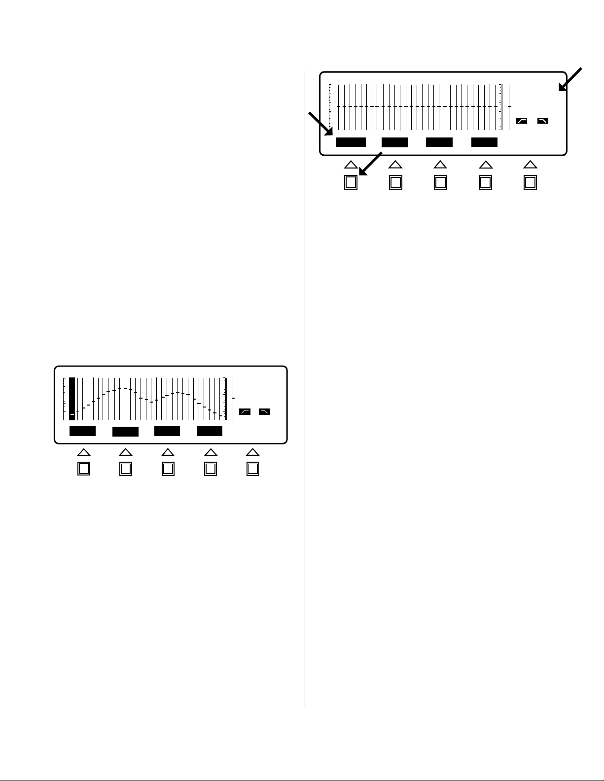
The LCD display should appear as shown in Figure 1.11
(if the DEQ is set to Preset 1). Note that the Softkey label
for the Active Preset (Preset 1 ) is in normal-video while
the other labels are in reverse-video. This serves as an
indication of the Active Preset number (the same
DEQ 1
PRE 1
OUT
OUT
Title:
()
ENTER
Figure 1.11: Presets 1 through 4
again appear as in Figure 1.11 except that the PRE 2
Softkey is now in normal-video indicating that Preset 2 is
the Active Preset. Note that only Preset 1 through 4 are
currently accessible. To access Preset 5 through 8 press
the Softkey labeled MORE and note that the Softkeys
have been relabeled as "PRE 5", "PRE 6", "PRE 7", "PRE
8", and "CANCEL", as shown in Figure 1.12.
If you decide not to change Presets simply push
"CANCEL" and you will be returned to the menu you
were in before you entered Preset Select mode.
To summarize the procedure for changing Preset:
1. Enter the Preset Select mode by pressing the Preset
Select key.
2. Push the Softkey that is labeled with the number of
the Preset to which you wish to change.
3. Push the Softkey labeled "MORE" to access Preset 5
through 8 and press "CANCEL" to exit Preset Select
mode without changing Presets.
Page 8
DEQ-II EQUALIZE MENU
TERMS USED
EQUALIZATION CURVE (or simply, CURVE):
A term describing the collection of filter settings
(bandpass, high-pass, or low-pass) that completely
define how the equalizer will process audio
REVERSE-VIDEO: Light characters on a dark
background
NORMAL-VIDEO: Dark characters on a light
background
SYSTEM PASSWORD: The password that
permits the highest level of access
TITLE: The name of a Preset
EQUALIZE MENU SCREEN and
EQUALIZE MENU SOFTKEY EXPLANATIONS
Described below are the functions of the Softkeys in
the EQUALIZE menu. Step-by-step examples of how
to use each function are included.
USING LOCK/UNLOCK
1
DEQ
8
PRE
25 Hz
0 dB
OUT
OUT
BYPASS
MUTE TITLELOCK
ENTER
1
DEQ
L1
PRE
OUT
OUT
BYPASS
MUTE TITLEUNLOCK
ENTER
Figure 2.1: Preset Lock
action that Softkey performs (see Figure 2.1). Also notice
that the Band Cursor has disappeared and the
frequency and setting information has been erased
from the Status Area to indicate that you may no longer
alter this Preset. Finally, note that the letter “L” appears
beside the Active Preset number in the Status Area. An
“L” in this location indicates that the Preset is LOCKed
and may not be modified without being UNLOCKed
by someone with the proper password.
To UNLOCK a LOCKed Preset simply press the
UNLOCK Softkey (provided the label for this Softkey is
in reverse-video; i.e., the function is available). The
Band Cursor and frequency and setting information
should return and the “L” should disappear from the
Status Area. Also, the function of the UNLOCK Softkey
should now be LOCK. The Preset may again be
modified as desired.
Figure 2.0: EQUALIZE Menu Screen
The LOCK/UNLOCK function allows a user with the
System Password to prevent modification of selected
Presets. Any number of Presets in any combination
may be LOCKed, provided the user has entered the
correct System Password (If the equalizer does not
have a password set, the LOCK/UNLOCK function is
available to anyone). To see how LOCK/UNLOCK is
used, enter the EQUALIZE menu by pressing the
EQUALIZE menu key. The Softkey labels should be
LOCK, BYPASS, MUTE, TITLE, and ENTER. All but
ENTER should be in reverse-video, indicating that
they may be used at this time.
Now, press the LOCK Softkey. You should see that
the function of the LOCK Softkey changes to
UNLOCK, which means that UNLOCK is now the
NOTE: If the system has been secured with passwords
then you may not have access to the LOCK/UNLOCK
function, depending on the level of the Password you
entered when logging on (see Chapter 5, System
Security). Only users with the System level password
may lock or unlock Presets.
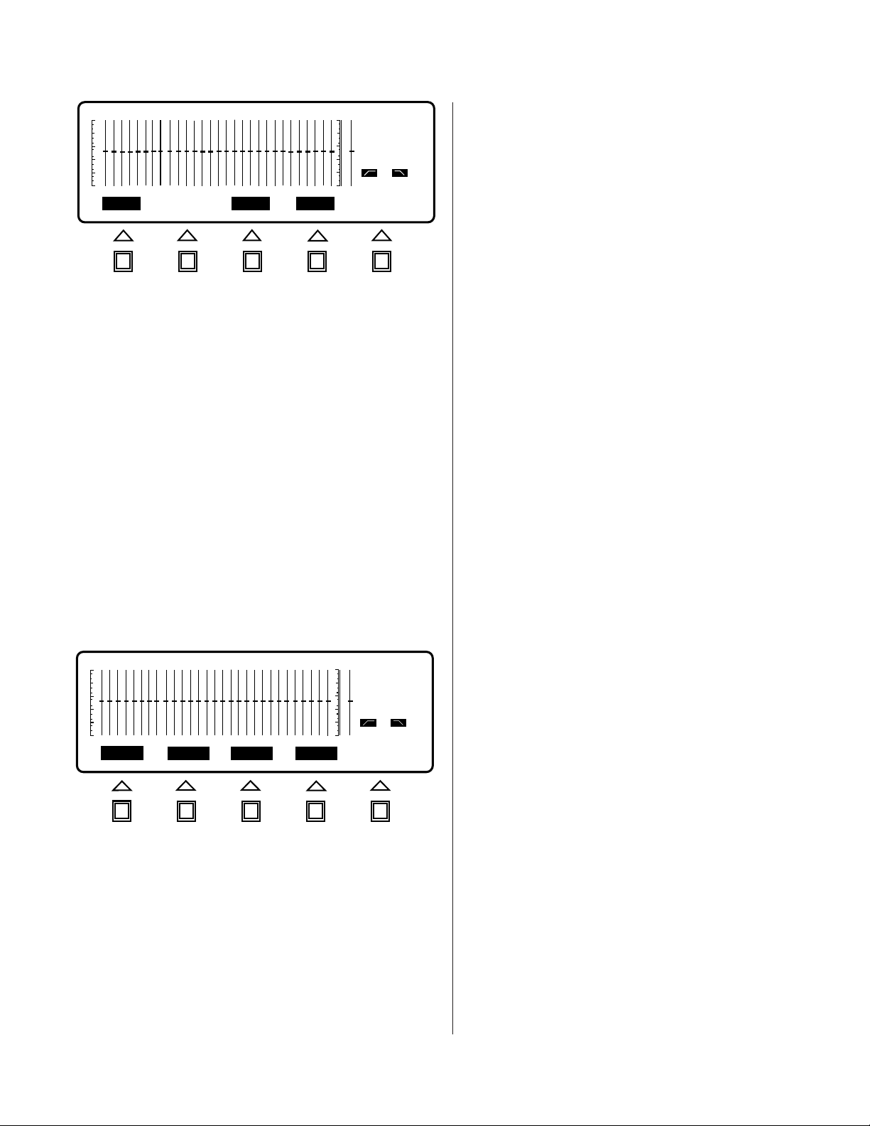
USING BYPASS/INSERT
It is often desirable to be able to quickly compare the
sound of the system with and without equalization.
That is, one would like to be able to, in effect, “remove”
the equalizer from the system and “reinsert” it at the
touch of a button. The BYPASS/INSERT Softkey
provides this function. The BYPASS function
temporarily sets all of the filters and the gain control to
0 dB (but doesn’t change the stored settings). Setting
the filters to 0 dB effectively removes the equalizer from
the system since no filtering is being performed. The
INSERT function restores the filters to their stored
settings.
Page 9

DEQ-II EQUALIZE MENU (CONTINUED)
To “remove” the equalizer from the system, access the
EQUALIZE menu by pressing the EQUALIZE menu
key. The Softkeys should be labeled LOCK (or
UNLOCK), BYPASS, MUTE, TITLE, and ENTER
(labels written in boldface are in reverse-video). If
BYPASS is not in reverse-video then the equalizer has
been muted and should be un-muted before
proceeding.
NOTE: EQUALIZE BYPASS/INSERT do not work
when the equalizer is muted. (See below: Using MUTE/
UNMUTE.)
Next, press the Softkey labeled BYPASS. Notice that
the label of the Softkey has changed to INSERT, which
denotes the function the Softkey now performs. Notice
1
DEQ
1
PRE
OUT
OUT
INSERT
MUTE TITLELOCK
BYPASSED
ENTER
To mute the equalizer, access the EQUALIZE menu by
pressing the EQUALIZE menu key. The Softkey labels
should be LOCK (or UNLOCK), BYPASS (or INSERT),
MUTE, TITLE, and ENTER. Press the Softkey labeled
MUTE. You should notice several changes in the display:
1. The MUTE Softkey has been relabeled UNMUTE to
denote the new function that the Softkey performs.
2. The Status Area has been updated to show that the
equalizer is mute (“MUTE” is displayed on line 7 of
the Status Area).
3. The BYPASS/INSERT Softkey has been placed in
normal video to indicate that it cannot be used while
the equalizer is muted (see Figure 2.3).
1
DEQ
1
PRE
25 Hz
0 dB
OUT
OUT
BYPASS
UNMUTE TITLELOCK
ENTER
MUTE
Figure 2.2: Bypassed
also that the Band Cursor and the Status information
pertaining to the Active Filter Band (if there was one)
have been blanked. This is because no filter
adjustments may be made while the EQUALIZE is
BYPASSED. Finally, the Status Area has been updated
to reflect that the equalizer is in EQUALIZE BYPASS
mode by displaying the message “BYPASSED” on line
7 of the Status Area (see Figure 2.2).
To “reinsert” the equalizer, access the EQUALIZE
menu and press the Softkey labeled INSERT. Doing
this changes the function of the Softkey back to
BYPASS, restores the Band Cursor (if there was an
Active Filter Band), and removes the “BYPASSED”
annunciation from the Status Area. The filters may
now be adjusted again.
USING MUTE/UNMUTE
Many times it may be desirable to mute the equalizer,
that is, prevent it from passing audio. This is
particularly useful when changing presets since you
may not know the level on the new preset until
changing to it. This section describes how to mute and
unmute the equalizer.
Figure 2.3: Mute
The equalizer is now muted.
To unmute the equalizer press the Softkey labeled
UNMUTE. Several things should happen:
1. The UNMUTE Softkey has been relabeled MUTE to
denote the new function that the Softkey performs.
2. The “MUTE” annunciation has been removed from
the Status Area.
3. The EQ BYPASS/INSERT Softkey has been placed in
reverse-video to indicate that the Softkey can be
used.
Of course, were the equalizer processing audio you
would also hear the effect of the MUTE/UNMUTE
function.
Page 10

DEQ-II EQUALIZE MENU (CONTINUED)
USING TITLE
Another capability afforded by the DEQ-II is the ability
to name the Presets, that is, to give them Titles. While
completely optional (Presets do not have to be Titled),
this feature can be a great help in identifying a given
curve. You might, for instance, want to give a Preset a
Title based on the time and date that the curve was
created, or one based on the source material for which
the equalization was done (e.g., speech or music). Preset
Titles may be up to 16 characters long. The procedure
described below details how to go about setting and
editing Preset Titles.
To Set A Preset Title:
1. From within the EQUALIZE menu, press the
softkey labeled TITLE. You will note that the
Softkey/Message Area has been replaced with
the legend “PRESET:.” If the Preset has not yet
been given a Title then there will be no
characters after the colon. You will also notice
at the right end of the Softkey/Message Area
that there are two Softkey labels: CANCEL and
ENTER. And again, the Band Cursor and band
status information have been blanked to
DEQ
1
PRE
1
OUT
OUT
PRESET:
PRESET NAME HERE
CANCEL
ENTER
CURSOR SELECT MENU
DEQ
OUT
ENTER
1
PRE
1 kHz
1
0 dB
OUT
DEQ
PRESET
EQUALIZE
EDIT
UTILITY
Figure 2.5: Cursor Keys
indicates which position in the Title will be
changed by the UP and DOWN keys. To
practice entering a Title, use the UP and
DOWN keys to find your first initial (see the
Character Set Chart on page 25, Appendix C, if you
have any trouble finding it). Once you have
found it, use the RIGHT key to move one
position to the right. Note that the character
you have already chosen remains in the first
position. Now, use UP and DOWN to set a
character for the second position. Continue
using the cursor keys to move the cursor and
select characters until you are comfortable with
these functions. Notice that when you cycle
beyond either end of the character set, the
character selection scrolls to the opposite end
of the character set. Also, when you attempt to
move the cursor beyond the ends of the 16–
character field the cursor scrolls to the opposite
end of the field. Note that you erase a
character by selecting the “space” character.
Figure 2.4: Preset
indicate that slider settings may not be adjusted.
Finally, in the position immediately to the right
of the colon there is a flashing cursor.
2. Titles are entered by using the UP and DOWN
cursor keys to cycle through the character set
and the LEFT and RIGHT cursor keys to
position the cursor (see Figure 2.5). The cursor
3. When you have entered the desired Title you
can store it by pressing the ENTER Softkey.
Doing so simultaneously stores the PRESET
Title in nonvolatile memory (as part of the
Preset) and returns you to the equalize menu.
If you decide not to store the PRESET Title,
simply press the CANCEL Softkey which will
return you to the EQUALIZE menu without
saving the Title.
The same Title may be used for more than one preset,
so be careful. Existing PRESET Titles are edited in
exactly the same way as new PRESET Titles are
entered.
Page 11

DEQ-II EDIT MENU
This chapter details the many advanced editing features
of the DEQ-II.
TERMS USED
EQUALIZATION CURVE (or simply, CURVE): A
term describing the collection of filter settings
(bandpass, high-pass and low-pass) that completely
define how the equalizer will process audio.
SOFTKEY/MESSAGE AREA: The portion of the
LCD display dedicated to displaying the Softkey
labels and messages.
ACTIVE FILTER BAND: The filter which may
currently be adjusted.
BAND CURSOR: A solid “bar” that overlaps the
slider “slot” of the Active Filter Band; denotes the
Active Filter Band.
NORMAL-VIDEO: Dark characters on a light
background.
REVERSE-VIDEO: Light characters on a dark
background.
PRESET: A group of settings that completely
configure the equalizer.
TITLE: A 16-character (or fewer) description for the
name of a Preset.
DEQ
1
1
PRE
OUT
OUT
PASTE
CLEAR TITLECOPY
ENTER
Figure 3.0: EDIT MENU SCREEN
EDIT MENU SCREEN and
EDIT MENU SOFTKEY EXPLANATIONS
Described in this section are the features and functions
of the EDIT menu Softkeys. Step-by-step examples aid
the user in gaining rapid proficiency in using these
functions.
USING COPY AND PASTE
Frequently it is desirable to make small enhancements to
an equalization for comparison purposes without
changing the stored curve. You might, for example,
have an equalization curve with which you are basically
happy but want to experiment, without destroying the
curve you like. One way to accomplish this is by
selecting a different Preset and manually adjusting the
faders until they are set exactly as in the curve you like.
A much better way, however, is by utilizing the COPY
(and PASTE) commands of the EDIT menu. Those
familiar with computers may recognize these commands
as being very similar to the editing functions provided
by most word processor programs. COPY and PASTE
may be used together to copy the curve settings from
one Preset to any other Preset, or even to a Preset in a
different DEQ. The following procedure describes the
steps involved in copying and pasting Presets.
Step One: Access the EDIT menu by pressing the EDIT
menu key. The Softkey/Message Area should now be
labeled COPY, PASTE, CLEAR, TITLE, and ENTER (see
Figure 3.0). Note that if the active Preset is locked you
will not have access to the CLEAR function (CLEAR will
be in normal-video). Note also that the Band Cursor and
band status information have been blanked from the
display to indicate that the faders may not be adjusted.
Faders may only be adjusted while in the EQ Menu.
Step Two: Press the Softkey labeled COPY. The COPY
Softkey will flash briefly and then the PASTE Softkey will
be placed in reverse-video (unless the active Preset is
locked: see page 9, Using Lock/Unlock). The flashing COPY
Softkey denotes that the curve has been correctly copied
into the copy buffer, and the reverse-video PASTE Softkey
indicates that the copied curve may now be pasted. If
the Preset is locked then the PASTE Softkey will remain
in normal-video until you change to a preset which is
not locked. You will need to select an unlocked Preset
(or unlock the current Preset) before the PASTE Softkey
is placed in reverse-video and the curve may be pasted.
If you cannot remember how to change Presets, see the
Quick Reference portion of this manual.
Step Three: Once you have selected the Preset to which
you wish to copy the curve, press the Softkey labeled
PA STE. The Softkey/Message Area should now display
the query “Overwrite Preset?” and the Softkey labels
CANCEL and PASTE (see Figure 3.1). If you decide you
do not want to paste the copied curve over this Preset
simply hit CANCEL and you will be returned to the EDIT
menu without having pasted the curve. The curve you
"copied" will still be held in the copy buffer until you
copy another curve or power down the equalizer. To
complete the paste operation press the PASTE Softkey.
The PASTE Softkey will flash briefly to
Page 12

DEQ-II EDIT MENU (CONTINUED)
DEQ 1
PRE
1
OUT
OUT
Overwrite Preset?
CANCEL
ENTER
Figure 3.1: PASTE Screen
indicate that a paste is in progress. Then the copied curve
is pasted into the new Preset. Finally, you are returned to
the EDIT menu. Go back to the Preset that you copied
the curve from and verify that the curves are identical.
Note that while modifications to locked Presets are not
allowed, the curves stored in locked Presets may be freely
copied to other (unlocked) Presets and adjusted in the
new Preset as desired. Also, remember that you may
change Presets or DEQs from within any of the main
menus (EQUALIZE, EDIT, and UTILITY).
USING CLEAR
Another desirable feature is the ability to erase the settings of a given Preset to restore the Preset to its default
settings. The CLEAR function provides this facility.
To clear a Preset:
Step One: Access the EDIT menu by pressing the EDIT
menu key. The Softkey/Message Area should now be
labeled COPY, PASTE, CLEAR, TITLE, and ENTER. Note
that if the active Preset is locked you will not have
access to the CLEAR function (CLEAR will be in
normal-video). Note also that the Band Cursor and band
status information have been removed from the display
as an indication that the faders may not be adjusted
(faders may only be adjusted while in the EQ menu). If
CLEAR is not shown in reverse-video you will need to
unlock the Preset before you may clear it.
Step Two: Once the CLEAR Softkey is labeled in reverse-
video it may be used. Press the CLEAR Softkey. You
should see the query “Clear Preset?” and the Softkey
labels CANCEL and CLEAR (see Figure 3.2). To abort
the clear process simply press the CANCEL Softkey and
you will be returned to the EDIT menu without clearing
the Preset. To complete the CLEAR process press the
CLEAR Softkey. You will notice that the curve has been
restored to its default settings and that you have returned
to the EDIT menu. Be careful, once a preset has been
"Cleared" all settings are lost.
Page 13
DEQ
1
1
PRE
OUT
OUT
CANCEL CLEARClear Preset?
Figure 3.2: CLEAR Screen
USING TITLE
(See USING TITLE on page 11 of this manual.)
To set a Preset Title:
Step One:
note that the Softkey/Message Area has been replaced
with the legend “PRESET:” with the name of the current
Preset. You will notice, at the right end of the Softkey/
Message Area, that there are two Softkey labels, CANCEL
and ENTER. The Band Cursor and band status
information have been blanked to indicate that settings
may not be adjusted. In the position immediately to the
right of the colon is a flashing cursor.
Press the Softkey labeled TITLE. You will
Step Two: Titles are entered by using the UP and DOWN
arrow keys to cycle through the character set and the
LEFT and RIGHT arrow keys to position the cursor. The
cursor indicates which position in the Title will be
changed by the UP and DOWN keys. To practice entering
a Title, use the UP and DOWN keys to find your first
initial. Use the RIGHT key to move one position to the
right. Note that the character you have already chosen
remains in the first position. Now, use UP and DOWN
to set a character for the second position. Continue using
the arrow keys to move the cursor and select characters
until you are comfortable with their functions. Notice
that when you cycle beyond either end of the character
set the character selection scrolls to the opposite end of
the character set. Also, when you attempt to move the
cursor beyond the end of the 16th character field, the
cursor scrolls to the opposite end of the field. Delete a
character by replacing it with a "space" character
Step Three: When you have entered the desired Title
you can store it by pressing the ENTER Softkey. Doing
so simultaneously stores the Title in nonvolatile memory
(as part of the Preset) and returns you to the EDIT menu.
By pressing the CANCEL Softkey, you will be returned
to the EDIT menu without saving the Title.

DEQ-II UTILITY MENU
This chapter describes the many miscellaneous features
of the DEQ-II that make up the UTILITY menu.
TERMS USED
SOFTKEY/MESSAGE AREA: The portion of the
LCD display dedicated to displaying the Softkey
labels and messages.
ACTIVE FILTER BAND: The filter which may
currently be adjusted.
BAND CURSOR: A solid “bar” that overlaps the
slider “slot” of the “Active Filter Band”; denotes the
Active Filter Band.
NORMAL-VIDEO: Dark characters on a light
background.
REVERSE-VIDEO: Light characters on a dark
background.
DATAWAY: The physical wiring that connects the
Communications Ports of multiple equalizers to form
a PA-422 network.
USING LOG OUT
The purpose of the Log Out function is to terminate an
equalization session. Log Out is used to tell the remote
DEQs, if any, that they are no longer under the control of
the DEQ-II you are working from.
NOTE: It is especially important to use the Log Out
function if your system uses the Password Security
System, as described in the SYSTEM SECURITY section
of this manual.
To LOG OUT from the equalizer:
Step One: Access the UTILITY menu by pressing the
UTILITY menu key. You will notice that the Softkey/
Message Area is now labeled LOG OUT, PASSWRD,
DISPLAY, NAME and ENTER. Also, notice that the Band
Cursor and band status information have been removed
from the display to denote that the sliders may not be
adjusted. If your system uses Passwords and you are
not logged on with the system password then
PASSWRD will be in normal-video, indicating that you
do not have access to these functions.
COMMUNICATIONS PORT: The PA-422
connector port on the back panel through which
serial data communications occur.
NAME: A 16-character (or fewer) description for the
name of an equalizer.
DEQ 1
PRE 1
OUT
OUT
LOG OUT
PASSWRD
DISPLAY NAME
ENTER
Figure 4.0: Utility Screen
UTILITY MENU SCREEN and
UTILITY MENU SOFTKEY EXPLANATIONS
The following sections give step-by-step examples and
descriptions of the features available under the UTILITY
menu. These functions are Log Out, Password, Display
and Name EQ.
Step Two: Press the LOG OUT Softkey. The Softkey/
Message area will now display the question " Secure Front
Panel?” Answering " YES " to this question will prevent
unauthorized persons (those without a password) from
changing Presets and from accessing other DEQs.
Answering " NO " will allow persons who don't know
the passwords to select Presets (using the Preset Select
button) and to access other DEQs. Note, however, that
this does not allow unauthorized persons to alter any of
the settings stored in those Presets or DEQs. After
answering the "Secure Front Panel?" question (by pushing
either the " YES " or the " NO " Softkey), you will be logged
out of the DEQ and, if passwords have been set, the system
will be secure.
SETTING PASSWORDS
Password security is an advanced feature that does not
have to be utilized. It is provided for those who desire
the added security that passwords provide. Chapter 5
gives a general explanation of the Password Security
System and how it provides the desired protection
without going into detail about how passwords are
actually set. This section provides the necessary details
for setting passwords.
NOTE: Write down any password you set.
(Continued on next page)
Page 14

DEQ-II UTILITY MENU (CONTINUED)
To set a password:
Be sure that all of the DEQs in the system (that you wish
to have password protection) are connected to the
dataway and are turned on. This ensures that all
equalizers will be set to the correct passwords, which is
important because the security system depends on the
passwords being stored in every unit (see Using Passwords
section on page 17 for details). You should try to address
each unit to be sure you have good communications.
(See Function section on page 18 and the Appendix for
interconnection details.)
DEQ 1
PRE
1
OUT
OUT
SYSTEM: ( ) USER: ( )
Figure 4.1: Password Screen
Access the utility menu by pressing the UTILITY menu
key. You will notice that the Softkey/Message Area is
now labeled LOG OUT, PASSWRD, DISPLAY, NAME
and ENTER. Also, notice that the Band Cursor and band
status information have been removed from the display
to denote that the filters may not be adjusted.
CANCEL
ENTER
password field press the LEFT cursor one time. Notice
that the cursor is now in the fourth position of the User
password field. If you the press the LEFT key four more
times, the cursor will then be located in the fourth
position of the System password field. Note that
passwords are only four characters long. Practice using
the cursor keys to set passwords until you are familiar
with them. If you are already familiar with using the
cursor keys to edit Preset Titles (see page 11) then you
shouldn’t have any problems.
If you do not wish to store the new passwords, simply
press CANCEL and you will be returned to the UTILITY
menu. To store the new passwords, press the ENTER
Softkey. WRITE DOWN THE PASSWORDS IN CASE
YOU FORGET THEM. ONCE YOU LOG OUT OF
THE SYSTEM YOU WON’T BE ABLE TO LOG BACK
IN WITHOUT THE CORRECT PASSWORD. After
accepting the passwords you have set by pressing
ENTER, you will notice that you have been returned to
the UTILITY menu.
Remember: The next time you attempt to log on to the
equalizer, you will have to enter one of the passwords
you have set, or you will be denied access.
USING DISPLAY
The Display function controls the LCD display. With the
DISPLAY command you can adjust the contrast of the
display and you can turn the backlight on and off. The
use of the Display function is described below.
Select the password menu item by pressing the
PASSWRD Softkey. The LCD display should appear as
shown in Figure 4.1. The two character fields enclosed by
braces contain the current System and User level
passwords. If your system does not have passwords set
at this time then the fields will be blank, as shown. A
flashing cursor is located in the first position of the
System password field. The cursor denotes which
position in the field may be edited.
Passwords are set (and edited) by using the UP and
DOWN cursor keys to cycle through the DEQ character
set, while the LEFT and RIGHT cursor keys are used to
select the position in the field that is edited. Push the
RIGHT cursor key four times. Notice that the cursor is
now located in the first position of the User password
field. If you use the UP and DOWN cursor keys now
you will edit the character at that position. Push the
RIGHT key four more times and the cursor will be at the
first position of the System password field again. The
LEFT key behaves in the same manner. For example,
with the cursor in the first position of the System
Page 15
1
DEQ
PRE
1
OUT
OUT
BACKLIGHT=
CONTRAST=UP/DOWN
DONEOFF
Figure 4.2: Backlight/Contrast Screen
To adjust the contrast:
Access the utility menu by pressing the UTILITY menu
key. You will notice that the Softkey/Message is now
labeled LOG OUT, PASSWRD, DISPLAY, NAME, and
ENTER. Also, notice that the Band Cursor and band
status information have been removed from the display
to denote that the filters may not be adjusted.
(Continued on next page)

DEQ-II UTILITY MENU (CONTINUED)
Select the Display function by pressing the Softkey
labeled DISPLAY (see Figure 4.2). Use the UP and
DOWN cursor keys to adjust the contrast of the display
screen for your viewing angle and lighting conditions.
ENTER. Also, notice that the Band Cursor and band
status information have been removed from the display
to denote that the filters may not be adjusted.
Select the display function by pressing the Softkey
labeled DISPLAY. To turn the backlight on or off, press
the ON/ OFF softkey.
NOTE: The backlight will turn itself off automatically
if there has been no activity on the front panel for five
minutes. This is to extend the life of the electro-luminescent panel used as a backlight. Touching any panel key
will activate the backlight for another five minutes, it
is best to press the currently active menu key since this
will not affect any EQ setting.
USING NAME
NAME is an advanced feature that allows you to give a
specific DEQ a name up to 16 characters long. While
you do not have to name the equalizer, you may find it
helpful to do so, particularly if you have several DEQs
in your system. If an equalizer is named, for example,
LEFT channel, you know immediately what part of the
system you are equalizing when you use that equalizer.
Equalizer Names are set and stored in exactly the same
manner as are Preset Titles. This procedure is repeated
here for clarity and convenience.
To Name a DEQ:
Access the utility menu by pressing the UTILITY menu
key. You will notice that the Softkey/Message is now
labeled LOG OUT, PASSWRD, DISPLAY, NAME, and
ENTER. Also, notice that the Band Cursor and band
status information have been removed from the display
to denote that the filters may not be adjusted.
Press the Softkey labeled NAME. You will note that the
Softkey/Message Area has been replaced with the
legend “DEQ:”, (see Figure 4.3). If the equalizer has not
yet been given a name then there will be no characters
after DEQ:. You will also notice, at the right end of the
Softkey/Message Area, that there are two Softkey labels,
CANCEL and ENTER. And again, the Band Cursor and
band status information have been removed to indicate
that slider settings may not be adjusted. Finally, a
flashing cursor appears in the position immediately to
the right of DEQ:.
keys to cycle through the character set and the LEFT
and DOWN keys. To practice entering a Name, use the
UP and DOWN keys to find your first initial (refer to
the Character Set Chart if you have any trouble finding
it). Once you have found it, use the RIGHT key to
move one position to the right. Note that the character
you have already chosen remains in the first position.
DEQ 1
PRE
1
OUT
OUT
DEQ NAME HERE
DEQ:
CANCEL
ENTER
Figure 4.3: DEQ Name
Now, use UP and DOWN to set a character for the
second position. Continue using the cursor keys to
move the cursor and select characters until you are
comfortable with their functions. Notice that when you
cycle beyond either end of the character set the
character selection scrolls to the opposite end of the
character set. Also, when you attempt to move the
cursor beyond the end of the 16th character field, the
cursor scrolls to the opposite end of the field. Delete a
character by replacing it with a "space" character.
When you have entered the desired name you can store
it by pressing the ENTER Softkey. Doing so
simultaneously stores the name in nonvolatile memory
and returns you to the UTILITY menu. If you decide
not to store the name simply press the CANCEL
Softkey which will return you to the UTILITY menu
without saving the name.
Existing names are edited in exactly the same way as
new names are entered.
Names are entered by using the UP and DOWN cursor
Page 16

SYSTEM SECURITY
USING PASSWORDS
The DEQ-I and DEQ-II employ a two-level Password
Security System to protect your system from
unauthorized tampering. A System Administrator who
wishes to use passwords has the ability to prevent access
to some or all of the equalizer’s functions through this
Password Security System. The password system
consists of two passwords, referred to as the System
level and User level passwords, respectively. A user
who logs on with the System password has access to
ALL of the equalizer’s functions, as described in the
preceding chapters. Someone logged on with the User
password has access to most, but not all, of the
equalizer’s functions. The User level user may not:
1. LOCK or UNLOCK Presets,
2. Set or edit Passwords, or
3. NAME an equalizer.
This scheme allows you to protect your own curves and
settings while granting limited access to some personnel
and entirely restricting all others.
The security system is enabled by setting system and
user level passwords as described on page 14, Setting
Passwords. Be sure that all equalizers in the system are
connected to the dataway and powered up when you set
the passwords so that the passwords will be set in each
DEQ. Having the passwords stored in each unit
increases system security by preventing someone using a
DEQ-II or PC without passwords from tampering with
your system.
Notice that none of the Menu LED indicators are on
because you have not yet selected a Main Menu.
DEQ
1
PRE
1
1 kHz
0 dB
OUT
OUT
E
ENTER
CURSOR SELECT MENU
DEQ
PRESET
EQUALIZE
EDIT
UTILITY
Figure 5.1: Main Menu Keys
Press one of the Main Menu keys (see figure 5.1)
EQUALIZE, EDIT, or UTILITY. Now, since passwords
have been set, the Softkey/Message Area displays the
query, “PASSWORD?” along with the Softkey labels
CANCEL and ENTER (see Figure 5.2). A four position
character field enclosed by braces is next to the
PASSWORD query, and a flashing cursor appears in the
first position of this field. The equalizer is waiting for
you to input a password.
DEQ 1
PRE
1
OUT
OUT
PASSWORD? ( )
CANCEL
ENTER
Once the system is password protected, logging on to the
equalizer is slightly different than was described on page
6, Logging On To The Equalizer. The log-on procedure
when using passwords is as follows:
Turn the equalizer on. After a few seconds the Oxmoor
logo will be displayed for a short time and will then be
replaced by the standard display screen, i.e., the active
curve and status information (see Figure 5.0). The
Softkey/Message Area displays the Active Preset Title.
DEQ 0
PRE 1
OUT OUT
MESSAGE AREA
PRESET:
Figure 5.0: Start-Up Screen
Figure 5.2: Password Entry
Use the arrow keys to select characters until the
character field contains one of the passwords (System or
User) that has been set in the equalizer. Once you have
entered a password with the arrow keys, press ENTER.
If the password matches one of the equalizer’s
passwords then you will be granted access and will be
in the menu corresponding to the Main Menu key you
pushed when attempting to log on. For instance, if you
had pressed the EQUALIZE menu key in step 2 of this
procedure, you will now be in the EQUALIZE menu.
The equalizer will continue to ask for a password until
you either enter a matching password or press
CANCEL. Pressing CANCEL returns the equalizer to
the state it was in before you pressed the Main Menu
key, i.e., at its start-up screen.
Once you have access to the equalizer you may use any
function allowed by your password level.
Page 17

DEQ-I & II MULTI-UNIT SYSTEM
FUNCTION
One of the primary benefits of programmable devices is
that several such devices may be connected together in a
network and controlled from a central location. Up to
250 DEQs (in any combination of DEQ-Is and DEQ-IIs)
may be connected together and controlled by controlling
devices (such as PCs and DEQ-IIs) from many, different
locations. This chapter describes how to connect the
equalizers so that they may all be remotely controlled by
the same controller.
DEQ-I Set To Address 1
PRESET SELECT
DEQ-II Set To Address 2
PA-422 OUTPUT PA-422 INPUT
PA-422 ADDRESS
128643216842
ON
1
NOTE: PA-422 requires that a devices address be
between 1 and 250. Address 0, 251, 252, 253, 254, and 256
are illegal.
TERMS USED
COMMUNICATIONS PORT: The connectors on
the back panel through which serial data
communications occur.
DATAWAY: The physical wiring that connects the
Communications Ports of two or more equalizers to
form a network.
ADDRESS SELECTOR: An eight-position dipswitch which sets the address of the equalizer.
PRESET: A nonvolatile memory for storing a group
of settings that completely configure an equalizer.
PRESET PORT: A 15-pin D-connector on the back
panel through which Presets may be selected.
STATUS AREA: The portion of the LCD display
dedicated to displaying Status information.
INTERCONNECTION SCHEME
Interconnecting equalizers to permit remote control is
easily accomplished through the Communications Port.
This example system consists of two DEQ-Is and a DEQII which is used as the system controller. Note that the
Communications Port of each DEQ consists of two ninepin D-connectors, one marked “PA-422 IN” and the
other “PA-422 OUT.” Notice that the “PA-422 OUT”
connector of one equalizer is connected to the “PA-422
IN” connector of another. For instance, in Figure 6.1, the
“PA-422 OUT” connector of the equalizer at address 1 is
connected to the “PA-422 IN” connector of the equalizer
at address 2. Similarly, the “PA-422 OUT” connector of
the DEQ-II is connected to the “PA-422 IN” connector of
the equalizer at address 3. This interconnection process
is extended when more equalizers (or PCs) are placed in
the system. For example, if you added a new equalizer
you could connect the new equalizer’s “PA-422 OUT”
PRESET SELECT PA-422 OUTPUT PA-422 INPUT
PA-422 ADDRESS
128643216842
ON
1
DEQ-I Set To Address 3
PRESET SELECT
PA-422 OUTPUT PA-422 INPUT
PA-422 ADDRESS
128643216842
ON
1
Figure 6.1: Interconnection Scheme
connector to the address 1 equalizer’s “PA-422 IN”
connector. Or, you could connect the new equalizer’s
“PA-422 IN” connector to the address 3 equalizer’s “PA422 OUT” connector. Please note that any mix of DEQIs and DEQ-IIs may be connected together, in any order,
provided the interconnection scheme described above is
followed and there are no more than 250 equalizers in
the network. Also, in this example addresses 1, 2, and 3
were chosen merely for convenience; any three
addresses in the range 1 to 250 could have been used.
The Appendix contains the appropriate wiring
information for the Communications Port, including
connector pin-outs.
SETTING ADDRESSES
NOTE: PA-422 requires that a device's address be
between 1 and 250. Address 0, 251, 252, 253, 254, and 256
are illegal.
When connecting two or more equalizers together to
form a network, as described in the preceding section, it
is important that each equalizer be given a unique
address. The Address Select dip-switch on the back
panel of both models of the equalizer allows you to give
each equalizer a numerical address ranging in value
from 1 to 250.
Page 18

DEQ-I & DEQ-II MULTI-UNIT SYSTEM (CONTINUED)
Each equalizer is set to Address 1 at the factory.
NOTE: PA-422 requires that a device's address be
between 1 and 250. Address 0, 251, 252, 253, 254, and 256
are illegal.
Each of the eight switches in the dip-switch has a
numerical value (see Figure 6.2). These values, reading
from left to right, are 128, 64, 32, 16, 8, 4, 2, and 1. To set
the address of an equalizer, place those switches whose
numerical value sum is equal to the desired address in
the ON position. For example, to set an equalizer to
address 23, the switches should be set as follows.
PA-422 ADDRESS
128643216842
ON
1
16 + 4+2+1 =23
Figure 6.2: Address Switch
Additional examples are shown in Figure 6.3:
PA-422 ADDRESS
128643216842
ON
1
will allow you to select a Preset by pushing momentary–
contact push buttons that are connected to the Preset Port.
The Preset Port will also provide a remote indication of
the Preset to which the equalizer is set. The advantage of
this capability is that you may configure your system so
that there are no controlling devices (i.e., PCs or DEQ-IIs)
yet personnel may still call up different Presets that you
have programmed. For example, you may have programmed one Preset to equalize for speech and another
for music and you may want to be able to switch between
these two Presets. A simple pair of momentary-closure
switches, appropriately connected to the Preset Port,
provides this function. Three "open collector " transistors
provide "tally" outputs at the Preset Select port.
These tallies, property decoded, can be used to provide a
remote indication of the active preset. Appendix F shows
one possible method of decoding tally outputs.
Figure 6.4 shows a typical wiring scheme for the Preset
Port. Here three DEQs are interconnected by their Preset
Ports and to a “remote control panel.” This control panel
is simply a set of switches (and possibly an indicator to
show the active Preset) which allow the selection of Presets. Although only three equalizers are shown in the illustration, any number of units (up to 250) may be connected together. These may consist of any mix of DEQ-Is
and DEQ-IIs.
16+8+4+2+1 =31
PA-422 ADDRESS
128643216842
ON
1
128 + 16 + 8 = 152
Figure 6.3: Address Switch
NOTE: It is very important that each equalizer on the
dataway has a unique address. If more than one equalizer has
the same address, the system will not work properly.
USING THE PRESET PORT
On page 8, we presented one way to select a different
Preset. In that method, the DEQ-II’s control panel was
used, which means that a DEQ-II must be in the system
and that you must be logged on to the system. A way to
switch the equalizer to a different Preset without needing
a DEQ-II (or a PC) is by using the Preset Select port. The
Preset Port, a 15-pin D-connector located on the back panel,
34
2
1
PRESET SELECT
PRESET SELECT PA-422 OUTPUT PA-422 INPUT
PRESET SELECT
5
6
PA-422 OUTPUT PA-422 INPUT
PA-422 OUTPUT PA-422 INPUT
7
PA-422 ADDRESS
128643216842
ON
PA-422 ADDRESS
128643216842
ON
PA-422 ADDRESS
128643216842
ON
Figure 6.4: Preset Interconnection
8
1
1
1
Page 19

DEQ-I & DEQ-II MULTI-UNIT SYSTEM (CONTINUED)
CURSOR SELECT MENU
DEQ
PRESET
EQUALIZE
EDIT
UTILITY
DEQ
PRE
1 kHz
0 dB
OUT
OUT
ENTER
1
1
Of course, if the equalizers are widely separated, it may
be impractical (due to conduit space or cost, for example) to interconnect the equalizers through both the
Communications and Preset Ports. Yet you may still
desire that the end user be able to call up the different
Presets without being able to alter them. Figure 6.5
shows how you can do this. Notice that there are two
DEQ-Is and a DEQ-II interconnected through their Communications Ports and that the remote control panel
shown is now attached only to the Preset Port of the
DEQ-II. If the system is idle, that is, no one is currently
logged on and performing equalization functions, then
pressing a switch on this control panel will cause the
DEQ-II to switch to the appropriate Preset. At the same
time, the DEQ-II tells the DEQ-Is to also change to that
Preset. While this scheme requires that a DEQ-II be
present in the system, it can greatly reduce the amount
of wiring necessary.
Another facility provided by the Preset Select port is
the ability to remotely mute all DEQs that are connected
through the Preset Select port. While pin 9 of the Preset
Select port is held "low" (as with a switch closure to
ground) all DEQs in the chain will be muted and will
not pass audio. Opening the switch will unmute the
DEQs (unless they have been programed to be muted).
SETTING UP MULTI-EQUALIZER SYSTEMS
Systems with Multiple Controllers
If your system is particularly large and spread out you
may find it convenient to be able to control the equalizers from multiple locations. The DEQ communication
scheme allows you to have many different controlling
devices (up to 250) in the network, but you may be
logged on to only one controller at a time. Preventing
multiple controllers from simultaneously controlling the
network greatly reduces the chances of conflicts. If you
attempt to log on to an equalizer and another equalizer
(or PC) already has control of the dataway, the message
“Controller Already on Dataway” will be displayed
on the LCD display of your DEQ-II. You will not be
able to log on to any DEQ-II in the network until the
active DEQ-II or PC logs off of the network.
Programming Multiple Equalizers
When a DEQ-II is first powered up it does not know if
there are any other equalizers in the system; it only
knows that it can program itself. Consequently, the
default active DEQ address (as shown in line 1 of the
Status Area) is the DEQ-II’s own address. Just as the
active Preset number denotes the Preset to which the
programming changes are being made, the active DEQ
address shows which equalizer is receiving programming changes. If you log on to a DEQ-II at address 2, for
example, and want to program an equalizer at address
5, you must first change the active DEQ address to 5.
Changing DEQs
You may change DEQs from within any of the main
menus. To do so, simply push the DEQ Select button
(see Figure 6.6).
Figure 6.6: Main Menu Selection
Several changes in the display should be evident (see
Figure 6.7). First, the Softkey/Message Area is now dis-
playing the Name of the active DEQ and the CANCEL
and ENTER Softkey have been placed in reverse-video.
Second, the Band Cursor has been turned off (if it was
on) and the Status Area has been updated to indicate
that no filter adjustments may be made (the Active Filter
Band frequency and setting are erased). Finally, the line
in the Status Area that indicates the active DEQ has
been placed in reverse-video. This indicates that the
active DEQ may be changed and an underline cursor
has appeared. This cursor allows you to change any of
the three character positions that are valid for DEQ # 1
through 250.
The reverse-video ENTER denotes that to select the
DEQ indicated in the Status Area you must push the
ENTER Softkey. Pressing CANCEL returns you to the
previous menu. Press the CANCEL Softkey now. The
Softkey/Message Area should now indicate that you
have returned to the menu you were in before you
pressed the DEQ Select button. Press the DEQ Select
button again to reenter the DEQ Select Mode. The DEQ
number is changed with the cursor keys, UP and
DOWN increments and decrements, respectively, the
value of the digit underscored by the flashing cursor,
while left and right position the cursor. This procedure
allows you to quickly select any of the 250 addresses
allowed by PA-422.
(Continued on next page)
Page 20

DEQ-I & DEQ-II MULTI-UNIT SYSTEM (CONTINUED)
For example, to change from a DEQ at address 1 to a
DEQ at address 201, you would move the cursor to the
first digit (the 100's place), using the left cursor and then
press the UP cursor twice. The DEQ number in the
status area would then read 201. Figure 6.8 illustrates
this procedure.
However, the curve displayed in the Curve Area has not
changed. This is because you have not yet entered the
new DEQ number, and the flashing cursor under the
DEQ
1
PRE
1
OUT
OUT
DEQ: HOUSE CURVE
CANCEL
ENTER
Figure 6.7: DEQ Selection
shown in line 1 of the Status Area. If you try to select a
DEQ address that is not on the network, then the LCD
display will give you a “Device Time-out - Unit Not
Responding” message and will wait for you to
acknowledge this message by pressing the CANCEL
Softkey.
To summarize the procedure for changing DEQs:
1. Enter the DEQ Select Mode by pressing the DEQ
Select key while in one of the main menus.
2. Use the CURSOR to select the desired DEQ.
3. Press the Softkey labeled ENTER.
One final, and very useful, function of the DEQ Select
button is the Last DEQ Recall feature. This function is
similar to the “last channel recall” feature of many
television remote controls in that it allows you to switch
between the last two active DEQs at the touch of one
button. The Last DEQ Recall feature allows you to
quickly move between two different equalizers without
having to go through the process of selecting new DEQs.
active DEQ number in the Status Area serves as a
reminder that you have not done so. To select the new
DEQ , push the Softkey labeled ENTER. Notice that the
cursor is no longer flashing and the active DEQ label in
the Status Area is now in normal video.
Also, the Softkey labels appropriate to the active menu
have replaced the Name in the Softkey/Message Area.
The curve now displayed in the Curve Area is the curve
for the new DEQ (unless the DEQ address you have
selected is not present on the network) and may be
adjusted as desired by following the procedures
described in the preceding sections. All subsequent
commands will be sent to the DEQ that has the address
CURSOR SELECT
DEQ: HOUSE CURVE
CANCEL
DEQ
201
PRE
1
OUT
OUT
ENTER
Figure 6.8: DEQ Address Selection
DEQ
PRESET
To explore the Last DEQ Recall feature enter the DEQ
Select Mode as described above by pressing the DEQ
Select Button. Now, note the active DEQ number as
displayed in the Status Area and use the cursor keys and
the ENTER Softkey to select a different DEQ as
described above.
Now, reenter the DEQ Select Mode (press the DEQ
Select key). Press the DEQ Select key again and notice
that the Status Area now reflects that the equalizer is set
to the previous DEQ. If the curves in the two DEQs (the
current DEQ and the one you were just on) are different
you will also see that the Curve Area has been updated
to show the new curve. Repeated pressing of the DEQ
Select key will cause the equalizer’s settings to toggle
back-and-forth between the last two active DEQs, just as
a TV remote control’s last channel recall function toggles
between the last two channels the TV was set to receive.
While in the DEQ Select Mode you may use the cursor
keys, as before, to change to new DEQs and still use the
Last DEQ Recall function without first having to exit the
DEQ Select Mode. The equalizer always remembers the
last two active DEQ addresses.
Page 21

DEQ-I INTERNAL CONTROLS
FUNCTION
Unlike the DEQ-II, the DEQ-I does not have a front
control panel to permit easy manipulation of its
settings; the primary usage of the DEQ-I is as a “slave”
being programmed by DEQ-IIs or PCs. However,
there may be times when you need to change settings
in a DEQ-I equalizer but do not have access to a DEQII, PC or a Macintosh. Therefore, a set of buttons have
been provided inside the DEQ-I which allow you to
manipulate its settings. The buttons are placed inside
the equalizer in order to retain system security. This
chapter shows you how to use the internal controls of
the DEQ-I.
IMPORTANT TERMS
Slave: An equalizer (DEQ-I or -II) that is under the
control of a DEQ-II, PC, or Macintosh.
Name: A 16-character (or fewer) descriptor for the
name of the equalizer.
Title: A 16-character (or fewer) descriptor for the
name of a Preset.
Preset: A nonvolatile memory for storing a group of
settings that completely configure the equalizer.
Active Filter Band: The filter which may currently
be adjusted.
Active Preset: The Preset that is currently being
adjusted.
INTERNAL CONTROL LOCATIONS
The internal controls are located inside the DEQ-I. In
order to use them you must first remove the top panel
of the equalizer. Figure 7.0 shows the approximate
locations of the internal controls.
USING THE INTERNAL CONTROLS
Through the internal controls you may select Presets,
Active (1/3–octave) Filter Bands and High– and Low–
Pass Filters. You may also adjust the filter settings and
overall gain. High level functions such as setting
Passwords, Names, and Titles cannot be performed
through the internal controls. Note that you do not
need to know the Password to use the internal controls.
DOWN
Figure 7.1: DEQ-I UP and DOWN Buttons
UP
SELECTING PRESETS
To select a Preset use the UP and DOWN buttons (see
Figure 7.1). Notice that each time you press either UP or
DOWN the number shown in the 7-segment display (see
page 8) changes to the next higher or lower number. If
you are processing audio you will also hear the different
Presets as they are selected.
(Continued on next page)
SELECT
ADJUST
Figure 7.0: DEQ-I TOP VIEW
DOWN
UP
Page 22

DEQ-I INTERNAL CONTROLS (CONTINUED)
SELECT
Figure 7.2: DEQ-I Select Button
ADJUSTING THE ACTIVE FILTER BAND
1. Push and hold the ADJUST internal control button
(see Figure 7.3). Notice that the 7-segment display is
now showing a two-digit number instead of the singledigit number it was showing. This two-digit number is
the setting of the Active Filter Band. Appendix E shows
how to interpret the setting (in dB) based on the number
in the 7-segment display.
2. While still holding down the ADJUST internal
control, push either the UP or the DOWN control and
notice that the new setting is displayed. If you are
processing audio you may also hear the change in the
audio.
SELECTING FREQUENCY BANDS
Selection of frequency bands is accomplished as
follows:
1. Push and hold the SELECT internal control (see
Figure 7.2). Notice that the 7-segment display is
now showing a two-digit number instead of the
single-digit number it was showing. This two-digit
number is the Active Filter Band number, which
denotes the filter band you are currently working
with. Appendix E provides a listing of the Active
Filter Band numbers and their corresponding 7segment display codes. You will need to refer to
this listing as you use the internal controls.
2. While still holding the SELECT internal control,
push either the UP or the DOWN control and
notice that the two-digit number changes to the
next higher or lower number. This new number
denotes the new Active Filter Band (refer to
Appendix E for which frequency band the new
number corresponds to). Notice that you are not
adjusting the filters, you are merely selecting a new
filter for adjustment.
3. After you are finished adjusting the frequency band,
release the ADJUST control. Notice that the 7-segment
display again displays the Active Preset number.
ADJUST
Figure 7.3: DEQ-I Adjust Button
3. When you have selected the desired frequency
band, release the SELECT control. Notice that the
7-segment display again displays a one-digit
number, which is the Active Preset number.
Page 23

C
T
APPENDIX A: HARDWARE INTERCONNECTION DETAILS
O
128643216842
1
PA-422 ADDRESS
ON
128643216842
1
PA-422 ADDRESS
ON
128643216842
1
PA-422 ADDRESS
ON
Figure A1: AUDIO IN & OUT CONNECTORS
PUSH
OXMOOR
MADE IN USA BY
OXMOOR CORPORATION
BIRMINGHAM, ALABAMA
INPUT
OUTPUT
Pin Number
2
1
Shield
High
The output may be set for either balanced (push-pull) or
unbalanced operation. In the unbalanced configuration,
pin 3 of the output connector is grounded, and the maximum output level drops by 6 dB.
To operate the output unbalanced, you must follow this
procedure; Remove the unit's top lid. Locate the configuration jumper block next to the output connector. The
jumper is factory-installed in the balanced position.
Observing the positions marked on the circuit board,
remove the jumper and reinstall it in the unbalanced
position.
On the output XLR, IN THE UNBALANCED MODE
ONLY, use pin 2 as "HOT" and pin 3 as "COMMON.” Pin
1 is to be used as "SHIELD.”
PIN 2 POSITIVE ON ALL
AUDIO CONNECTORS
Low
3
Figure A3: PA-422 IN & OUT CONNECTORS
SELECT
PA-422 OUTPUT
Pin 9
PA-422 OUTPUT
Female Connector
Function
Pin
1 ........ To DSR +
2 ........ To DSR -
3 ........ No Connection
4 ........ To RXD +
5 ........ To RXD -
6 ........ From DTR +
7 ........ From DTR -
8 ........ From TXD +
9 ........ From TXD -
Pin 1
PA-422 INPUT
PA-422 INPUT
Male Connector
Pin Function
1 ............ DSR +
2 ............ DSR -
3 ............ No Connection
4 ............ RXD +
5 ............ RXD -
6 ............ DTR +
7 ............ DTR -
8 ............ TXD +
9 ............ TXD -
PA-422 ADDRESS
128643216842
ON
Pin 9
Figure A4: ADDRESS SELECT SWITCH
PA-422 ADDRESS
UT
PA-422 INPUT
128643216842
ON
1
FUSE
1
S
POWER
Figure A2: PRESET SELECT CONNECTOR
ON ALL
ECTORS
Pin 15
Pin Number
PRESET SELECT
PRESET SELECT
Female Connector
1 ................... Preset 1
2 ................... Preset 2
3 ................... Preset 3
4 ................... Preset 4
5 ................... Preset 5
6 ................... Preset 6
7 ................... Preset 7
8 ................... Preset 8
9 ................... Mute
10 ................. Tally 0, LSB (1's)
11 ................. Tally 1, BIT (2's)
12 ................. Tally 2, MSB (4's)
13 .................+5 VDC
14 ................. Common
15 ................. Common
Pin 1
PA-422 OUTPUT
Function
PA-422 INPUT
NOTE: PA-422
requires that a
device's address
be between 1 and
250. Address 0,
251, 252, 253, 254,
and 256 are
illegal.
FACTORY SETUP:
The DEQ-I & DEQII are shipped from
the factory with the
PA-422 ADDRESS
set to 1.
EXAMPLES
16 + 4+2+1 =23
16+8+4+2+1 =31
128 + 16 + 8 = 152
Page 24

APPENDIX B: ERROR MESSAGES APPENDIX C: CHARACTER SET
This section lists the DEQ-II error messages with brief descriptions of their meanings and possible corrective actions.
“Com... Time-out -Device Not Responding” - The
DEQ you have attempted to communicate with is not
responding. Check the wiring to that unit. Make sure
that the unit is ON. Make sure that the unit has the
correct address.
“Illegal Device Type Returned” - The device you
have tried to communicate with is not a DEQ 1/3octave equalizer. Check the unit at that address.
“Incorrect Address ID Returned” - The remote device
has returned an address that does not match the
address you tried to select. Check your wiring. Make
sure that each equalizer has a unique address.
“Invalid Password - Access Denied” - Your password
does not match the password of the remote device.
You may not communicate with this device until you
know its password.
“Preset Locked - Access Denied” - The Preset you
have tried to modify is locked. You must unlock the
Preset before you can modify it.
"Incorrect ID Code Returned" - The remote device has
returned an ID code other than Oxmoor's. This
indicates that the unit you have addressed is not an
Oxmoor Product. Check your address settings on the
remote devices.
"Parity Error" - A parity error was present in the
command or data sent to the remote device. Check
your cabling and make sure that each device has a
unique address.
"Bad Data Received By Remote" - The remote device
has received data that is invalid. Check the wiring and
addresses.
"Bad Command Received By Remote" - The remote
device has received a command that is invalid. Check
the wiring and addresses.
This section lists the valid characters in the DEQ
character set.
Character Character
Number
1 ................... SPACE
2 ........................ A
3 ........................ B
4 ........................ C
5 ........................ D
6 ........................ E
7 .........................F
8 ........................ G
9 ........................ H
10 ........................ I
11 ........................ J
12 ....................... K
13 ....................... L
14 ....................... M
15 ....................... N
16 ....................... O
17 ....................... P
18 ....................... Q
19 ....................... R
20 ........................ S
21 ....................... T
22 ....................... U
23 ....................... V
24 ....................... W
25 ....................... X
26 ....................... Y
27 ....................... Z
28 ........................ 0
29 ........................ 1
30 ........................ 2
31 ........................ 3
32 ........................ 4
33 ........................ 5
34 ........................ 6
35 ........................ 7
36 ........................ 8
37 ........................ 9
38 ........................ $
39 ....................... %
40 ........................ ‘
41 ........................ -
42 ....................... @
43 ....................... ~
44 ........................ '
45 ........................ !
46 ........................ #
47 ........................ (
48 ........................ )
49 ....................... &
Page 25

APPENDIX D: GLOSSARY
This section contains a glossary of important terms.
ACTIVE DEQ - The equalizer currently under
control by the master device. The address of the
Active DEQ is shown on line one of the Status Area
(DEQ-II).
ACTIVE FILTER BAND - The filter which may
currently be adjusted. The Active Filter Band is
denoted by the “Band Cursor” and the frequency of
the Active Filter Band is shown on line three of the
Status Area of the DEQ-II or on the seven-segment
display of the DEQ-I.
ACTIVE PRESET - The Preset that is currently being
adjusted. The Active Preset number is shown on line
two of the Status Area of the DEQ-II or on the seven–
segment display of the DEQ-I.
ADDRESS SELECTOR - An eight-position dipswitch which sets the address of the equalizer. The
address is important for multi-equalizer systems.
BAND CURSOR - A solid “bar” that overlaps the
slider “slot” of the “Active Filter Band”. The Band
Cursor denotes the Active Filter Band (DEQ-II).
COMMUNICATIONS PORT - The connectors on
the back panel of the equalizer that are used for
conveying serial data information.
LOCKED PRESET - A Preset that cannot be modified.
LOGGING OFF - Term which describes the act of
relinquishing control of a DEQ-II and the equalizers
under the control of that DEQ-II.
LOGGING ON - Term which describes the act of
gaining access to a DEQ-II through its front panel;
accomplished by selecting a Main Menu key and
(possibly) giving a Password following power-up.
NAME - A 16-character (or fewer) description for the
name of an equalizer.
NORMAL-VIDEO - A display mode in which dark
characters are on a light background; typically denotes
an inactive function (DEQ-II).
PRESET - A group of settings that will completely
configure an equalizer.
PRESET PORT - A 15-pin D-connector on the back
panel through which Presets may be selected.
REVERSE-VIDEO - A display mode in which light
characters are placed on a dark background; typically
denotes an active function (DEQ-II).
SOFTKEY - Button on the front panel of the DEQ-II that
changes functions depending on the menu you are in.
CURVE AREA - The portion of the LCD display
dedicated to displaying the “Active Preset” curve
(DEQ-II).
DATAWAY - The physical wiring that connects the
Communications Ports of equalizers to form a
network.
EQUALIZATION CURVE (or simply, CURVE) - A
term describing the collection of filter settings
(bandpass, high-pass and low-pass) that completely
define how the equalizer will process audio.
HARDKEY - Button on the front panel of the DEQ-II
that always performs the same function.
SOFTKEY/MESSAGE AREA - The portion of the LCD
display dedicated to displaying the Softkey labels and
messages (DEQ-II).
STATUS AREA - The portion of the LCD display
dedicated to displaying Status information (DEQ-II).
SYSTEM PASSWORD - Password that gives the
highest level of access.
TITLE - A 16-character (or fewer) descriptor for the
name of a Preset.
USER PASSWORD - Password that permits access to
most, but not all, of the equalizer’s functions.
Page 26

APPENDIX E: DEQ-I DISPLAY CODES
This section lists the codes that are displayed on the DEQ-I’s
7-segment display. Note that these are the standard ISO band
numbers for the frequencies listed.
When selecting frequency bands the codes are:
Display Active
Code Filter Band
14 25 Hz
15 31.5 Hz
16 40 Hz
17 50 Hz
18 63 Hz
19 80 Hz
20 100 Hz
21 125 Hz
22 160 Hz
23 200 Hz
24 250 Hz
25 315 Hz
26 400 Hz
27 500 Hz
28 630 Hz
29 800 Hz
30 1.0 kHz
When selecting High-Pass and Low-Pass filters the codes
are:
HP FILTER
Display Band
Code Settings
0 OUT
1 20Hz
2 22.4Hz
3 25Hz
4 28Hz
5 31.5Hz
6 35.5Hz
7 40Hz
8 45Hz
9 50Hz
10 56Hz
11 63Hz
12 71Hz
13 80Hz
14 90Hz
15 100Hz
16 112Hz
17 125Hz
18 140Hz
19 160Hz
20 180Hz
21 200Hz
Display Active
Code Filter Band
31 1.25 kHz
32 1.6 kHz
33 2.0 kHz
34 2.5 kHz
35 3.15 kHz
36 4.0 kHz
37 5.0 kHz
38 6.3 kHz
39 8.0 kHz
40 10.0 kHz
41 12.5 kHz
42 16.0 kHz
97 GAIN
98 HP
99 LP
LP FILTER
Display Band
Code Settings
02k
1 2.2k
2 2.5k
3 2.8k
43.15k
53.55k
64k
7 4.5k
85k
9 5.6k
10 6.3k
11 7.1k
12 8k
13 9k
14 10k
15 11.2k
16 12.5k
17 14k
18 16k
19 18k
20 20k
21 OUT
When adjusting the Active Filter Band the codes are:
Display Filter
Code Setting
-12 -12.0 dB
-11 -11.5 dB
-11 -11.0 dB
-10. -10.5 dB
-10 -10.0 dB
-9.5 -9.5 dB
-9.0 9.0 dB
-8.5 -8.5 dB
-8.0 -8.0 dB
-7.5 -7.5 dB
-7.0 -7.0 dB
-6.5 -6.5 dB
-6.0 -6.0 dB
-5.5 -5.5 dB
-5.0 -5.0 dB
-4.5 -4.5 dB
-4.0 -4.0 dB
-3.5 -3.5 dB
-3.0 -3.0 dB
-2.5 -2.5 dB
-2.0 -2.0 dB
-1.5 -1.5 dB
-1.0 -0.1 dB
-0.5 -0.5 dB
0 0.0 dB
0.5 0.5 dB
1.0 1.0 dB
1.5 1.5 dB
2.0 2.0 dB
2.5 2.5 dB
3.0 3.0 dB
3.5 3.5 dB
4.0 4.0 dB
4.5 4.5 dB
5.0 5.0 dB
5.5 5.5 dB
6.0 6.0 dB
6.5 6.5 dB
7.0 7.0 dB
7.5 7.5 dB
8.0 8.0 dB
8.5 8.5 dB
9.0 9.0 dB
9.5 9.5 dB
10 10.0 dB
10. 10.5 dB
11 11.0 dB
11. 11.5 dB
12 12.0 dB
Page 27

APPENDIX F: PRESET SELECT TALLY
The following circuit can be used to decode the Preset
Select port tallies and give an indication of the active
preset. For example, if the DEQ is set to preset 1 then
LED 1 will be “on” and the others will be “off.” Likewise, if the DEQ is set to preset 8 then LED 8 will be
“on” and the others will be “off.” The RC networks provide protection from static shocks. Ground for the circuit should be tied to the DEQ ground through the Preset Select port (pin 14 and/or 15). The 5VDC supply
can be either user supplied or can be obtained from the
5 VDC
FROM
TALLY 0
FROM
TALLY 1
FROM
TALLY 2
5 VDC
5 VDC
10 K
10 K
10 K
.1 uF
5 VDC
.1 uF
.1 uF
1
2
3
4
6
5
5 VDC
AO
YO
A1
Y1
A2
Y2
LE
Y3
Y4
CS1
Y5
CS2
Y6
Y7
16 8
DEQ Preset Select port (pin 13). Using this circuit and
eight momentary action switches appropriately con-
nected to the preset port (pins 1 through 8) a remote
panel can be built to change presets and indicate which
preset is active.
Note: If the DEQs connected together through preset
port are not all on the same preset the tallies cannot
properly indicate the active preset (since there is no
one active preset).
5 VDC
15
13
13
12
11
10
ULN280374HC237
1
IO
2
I1
3
I2
4
I3
5
I4
6
I5
7
9
7
I6
8
I7
9
GND
YO
Y1
Y2
Y3
Y4
Y5
Y6
Y7
18
17
16
15
14
13
12
11
LED 1
LED 2
LED 3
LED 4
LED 5
LED 6
LED 7
LED 8
Page 28

INSTALLATION & SET-UP NOTES
Page 29

INSTALLATION & SET-UP NOTES
Page 30

DEQ-I & DEQ-II SPECIFICATIONS
FREQUENCY RESPONSEFREQUENCY RESPONSE
FREQUENCY RESPONSE 20 Hz to 20 kHz ............................ +0, – 0.3 dB
FREQUENCY RESPONSEFREQUENCY RESPONSE
HUM AND NOISEHUM AND NOISE
HUM AND NOISE Ref. +4 dBm Output @ Unity Gain . - 85 dB ( 20 Hz to 20 kHz BW, unweighted )
HUM AND NOISEHUM AND NOISE
DISTORTIONDISTORTION
DISTORTION Ref. +4 dBm Output @ Unity Gain
DISTORTIONDISTORTION
1/3 OCTAVE FILTERS1/3 OCTAVE FILTERS
1/3 OCTAVE FILTERS Type.............................................. Constant Q, minimum phase, combining
1/3 OCTAVE FILTERS1/3 OCTAVE FILTERS
FILTER CONTROLS &FILTER CONTROLS &
FILTER CONTROLS & Range ........................................... ±12dB
FILTER CONTROLS &FILTER CONTROLS &
GAIN CONTROLGAIN CONTROL
GAIN CONTROL Step Size ....................................... 0.5 dB
GAIN CONTROLGAIN CONTROL
HIGH–PASS FILTERHIGH–PASS FILTER
HIGH–PASS FILTER Slope Rate .................................... 12 dB/octave
HIGH–PASS FILTERHIGH–PASS FILTER
LOW–PASS FILTERLOW–PASS FILTER
LOW–PASS FILTER Slope Rate .................................... 12 dB/octave
LOW–PASS FILTERLOW–PASS FILTER
AUDIO INPUTAUDIO INPUT
AUDIO INPUT Type.............................................. Electronically balanced (RF suppressed)
AUDIO INPUTAUDIO INPUT
AUDIO OUTPUTAUDIO OUTPUT
AUDIO OUTPUT Type.............................................. Electronically balanced, (unbalancing jumpers provided)
AUDIO OUTPUTAUDIO OUTPUT
PRESET SELECT PORTPRESET SELECT PORT
PRESET SELECT PORT Input Type ..................................... Active low, internal pull-ups, diode isolation
PRESET SELECT PORTPRESET SELECT PORT
PROGRAMMING PORTPROGRAMMING PORT
PROGRAMMING PORT Serial Interface .............................. PA-422
PROGRAMMING PORTPROGRAMMING PORT
- 3 dB Points, Ref.1kHz .................. 4 Hz to 60 kHz (+ 4 dBm output)
THD + NOISE ........................... - 80 dB/0.01% (20 Hz to 20 kHz BW)
SMPTE IMD ............................ - 80 dB/0.01% (60Hz + 7kHz, mixed 4:1)
Transient Intermodulation .............. - 80 dB/0.01% (3.15kHz SQ + 15kHz probe, 30kHz BW)
Number ........................................ 29
Frequencies .................................. 25 Hz thru 16 kHz
Centers ......................................... ISO 1/3 octave standard
Bandwidth & Center Freq. Tolerance ± 5%
Combining Ripple .......................... 1.5dB max
Step Size Tolerance ....................... ± 0.05dB
-3 dB Point .................................... Selectable on 1/6 octave spacings from 20Hz to 200Hz
-3 dB Point .................................... Selectable on 1/6 octave spacings from 2kHz to 20kHz
Connector ..................................... Female XLR
Pin Out ......................................... Pin 1 shield (chassis), pin 2 +, pin 3 –
Input Impedance ........................... 80k ohms
Nominal Input Level ...................... 0 dBu
Maximum Input Level .................... +20 dBu
Common Mode Rejection Ratio ...... 50 dB @ 1kH
Connector ..................................... Male XLR
Pin Out ......................................... Pin 1 shield (chassis), pin 2 +, pin 3 –
Source Impedance ........................ 150 ohms (75 ohms/side)
Recommended Load Impedance ... 600 ohms or greater
Nominal Output Level .................... 0dBu (w/EQ flat, 0 dBu input)
Maximum Output Level
(Ref. 1 kHz @ Rated THD)
Terminated w/600 Ohms ......... +18 dBm
Unterminated ........................... +20 dBu
Tally Out........................................ Binary out, 3–digit encoded preset number
Preset Select Logic Action.............. Latching, mutual release; uses momentary closure
Mute & Enable Logic Action ........... Nonlatching: requires maintained closure
Connector ..................................... Female 15–pin Std. D-Sub w/locking screws
Input Protection ............................. 1/2 max. line voltage, 12kV static
Input Logic Levels (At Connector) ... Low < 3 volt, noise margin 3.8 volt min.
Maximum Parallel Inputs ............... 32
Maximum Input Sink
Current Required ...................... 100mA
Maximum Cable Length ................. 600m (2000f t), #22AWG
Switching Time .............................. 50ms
Power Output ................................ +5VDC, ± 0.1V; 20mA, current limited, diode isolated
MAINS POWERMAINS POWER
MAINS POWER Power Requirements......................... 100 to 130 VAC
MAINS POWERMAINS POWER
ENVIRONMENTALENVIRONMENTAL
ENVIRONMENTAL Storage Temperature ........................ - 20° C to 60°C (- 4° F to 140° F)
ENVIRONMENTALENVIRONMENTAL
MECHANICALMECHANICAL
MECHANICAL DEQ-I Packaging ...............................44 H x 483 W x 343 D mm
MECHANICALMECHANICAL
OPTIONAL ACCESSORYOPTIONAL ACCESSORY
OPTIONAL ACCESSORY TWEEQ Software .............................. Specify TWEEQ-IBM or TWEEQ-Macintosh
OPTIONAL ACCESSORYOPTIONAL ACCESSORY
Operating Temperature ..................... 0° C to 50° C (32° F to 122° F)
Humidity .......................................... Less than 80% RH, non-condensing
DEQ-II Packaging ..............................76 H x 483 W x 343 D mm
Finish ...............................................Textured black paint
Includes software, PA-422 conversion box, PC - to - converter cable
50 to 60 Hz; 16 watts maximum
( 1.72 H x 19 W x 13.5 D in )
Shipping: 6.3 Kg (14 lb)
Net: 5.9 Kg (13 Lb )
(3 H x 19 W x 13.5 D in)
Shipping: 7.2 Kg (16 lb)
Net: 6.8 Kg (15 Lb )
Page 31

OXMOOR FACTORY SERVICE
For service information contact:
Oxmoor Product Service Department
309 Cahaba Valley Parkway
Birmingham, Alabama 35124
E-mail: info@oxmoor.com
Additional Installation & Operation Manuals are available from Oxmoor. Contact the
Oxmoor Sales Department for pricing and other ordering information. Consult
warranty statement for cautions concerning unauthorized service.
Telephone: (205) 982-8200
Toll Free: 1 (800) 262-6898
Fax: (205) 982-8250
Internet: www.oxmoor.com
OXMOOR TWO YEAR LIMITED WARRANTY
Oxmoor warrants that each Oxmoor electronic product shall be free from defects in workmanship
and materials and will, at its option, repair or replace any part of the product without charge
provided the product is delivered to Oxmoor within two years of date of original purchase from
or delivery by an authorized Oxmoor dealer. Excluded from this warranty are finish and
appearance items and malfunction resulting from abuse, from use that is not in accordance with
instructions, or operation under other than specified conditions. Also excluded are incidental or
consequential damages except where precluded by applicable law. This warranty provides the
customer with specific legal rights; there may also be other rights which vary from state to state.
Repair by other than Oxmoor Factory Service Department or its authorized service agency,
unauthorized modification, or the removal or defacing of the serial number will void this
warranty.
Products returned for factory warranty service must be prepaid and packaged in such a way as to
insure safe transit and must be accompanied by a sales slip or other valid proof of purchase date.
PRIOR AUTHORIZATION FROM OXMOOR IS REQUIRED FOR RETURN. Contact Oxmoor for
a Return Authorization (R.A.) Number and shipping information before returning product for
service.
CONTACT
OXMOOR
Oxmoor Corporation, LLC, 309 Cahaba Valley Parkway, Birmingham, AL 35124 USA
Toll Free 1 (800) 262-6898 Telephone (205) 982-8200 Fax (205) 982-8250 E-mail info@oxmoor.com
For 24-hour access to product specs and information visit Oxmoor's complete product line on the internet at www.oxmoor.com.
Oxmoor is a registered trademark of Oxmoor Corporation, LLC.
Specifications and design are subject to change without notice.
Oxmoor DEQ-I & DEQ-II
Rev. 2.4/072501 Part Number:1700010
 Loading...