

oxic XPM9A261A, XPM9A261AR, XPM9A261AS, XPM9A261ALS, XPM9A261AL Installation Manual
...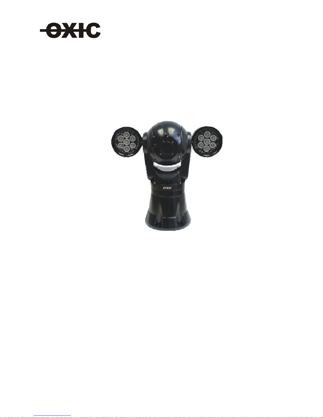
INTEGRATED ROBO PTZ CAMERA
INSTALLATION & PROGRAMMING MANUAL
MODELS :
XPM9A261A SONY 26X Optical zoom
XPM9A261AL SONY 26X Optical zoom with laser ( optional 150, 200 or 300 m )
XPM9A261AR SONY 26X Optical zoom with IR
XPM9A261AS SONY 26X Optical zoom with picture stabilization
XPM9A261ALS SONY 26X Optical zoom with picture stabilization and laser ( optional 150, 200 or 300 m )
XPM9A261ARS SONY 26X Optical zoom with IR and picture stabilization
XPM9A361A
SONY 36X Optical zoom
XPM9A361AL SONY 36X Optical zoom with laser ( optional 150, 200 or 300 m )
XPM9A361AR SONY 36X Optical zoom with IR

Contents
Chapter 1 INSTRUCTION
1.1 Forward
1.2 Appearance
1.3 Function explanation
Chapter 2 Notice proceeding of Installation
2.1 Safety Notice
2.2 Preparation of installation
2.3 Notice of installation
Chapter 3 Notice proceeding of Installation
3.1 Pedestal stand mode
3.2 Wall stand mode
Chapter 4: TECHNICAL PARAMETER
4.1 Structure
4.2 Rotation Index
4.3 Electric Index
4.4 Camera module Parameter
4.5 IR lamps Parameter
Chapter 5 OPERATION
5.1 Auto configure after Power On
5.2 Basic Function Operation
5.3 Special Function Preset
5.4 screen character display
Chapter 6 OSD OPERATION
6.1 Operation Introduction
6.2 Main Menu
6.3 Second Menu
6.3.1 System Menu
6.3.2 Screen display setting menu
6.3.3 Camera parameter setting menu
6.3.4 Pan/Tilt Menu
6.3.5 Privacy Zone Menu
6.3.6 Power on Mode
6.3.7 AUX Control
6.3.8 Language setting menu
6.3.9 Camera Reset
Appendix 1 Dial Switching Setting
Appendix 2 Pelco P Protocol
Appendix 3 Pelco D Protocol
Appendix 4 Troubleshooting and Resolution

Chapter 1: INSTALLATION MANUAL
1.1 FORWARD
1.2 Appearance
1.3 Function explanation
1.1 FORWARD
This manual introduces the function, installation and operation of the shock-proof integrated high speed camera in
details. Please thoroughly familiarize yourself with the information in this manual prior to installation.
This series integrated camera system is ideal for special occasions, such as airports, frontier defense, customs and
highway etc. It has many features: reliable, stable, airproof, acid water proof, , be able to bear high temperature, aging,
strong wind and so on. It adapt to the following hard conditions, such as high wind power, gap difference temperature
conditions, high electromagnetism and thunder disturb, all day working conditions.
This series system is high speed,changeable system and it can run smoothly and stablely.
This series camera is integrated with high speed decoder, IOP shield, heater, wiper, sun shade and insulating
materials. The optical module with a changeable focus lens which is DSP(Digital Signal Processing) camera.
Protocol P/D is used in this series of cameras. It can support most popular system platforms. This manual will not
explain the operation of other system if connecting with other system, please contact with the system manufacture or
dealer.
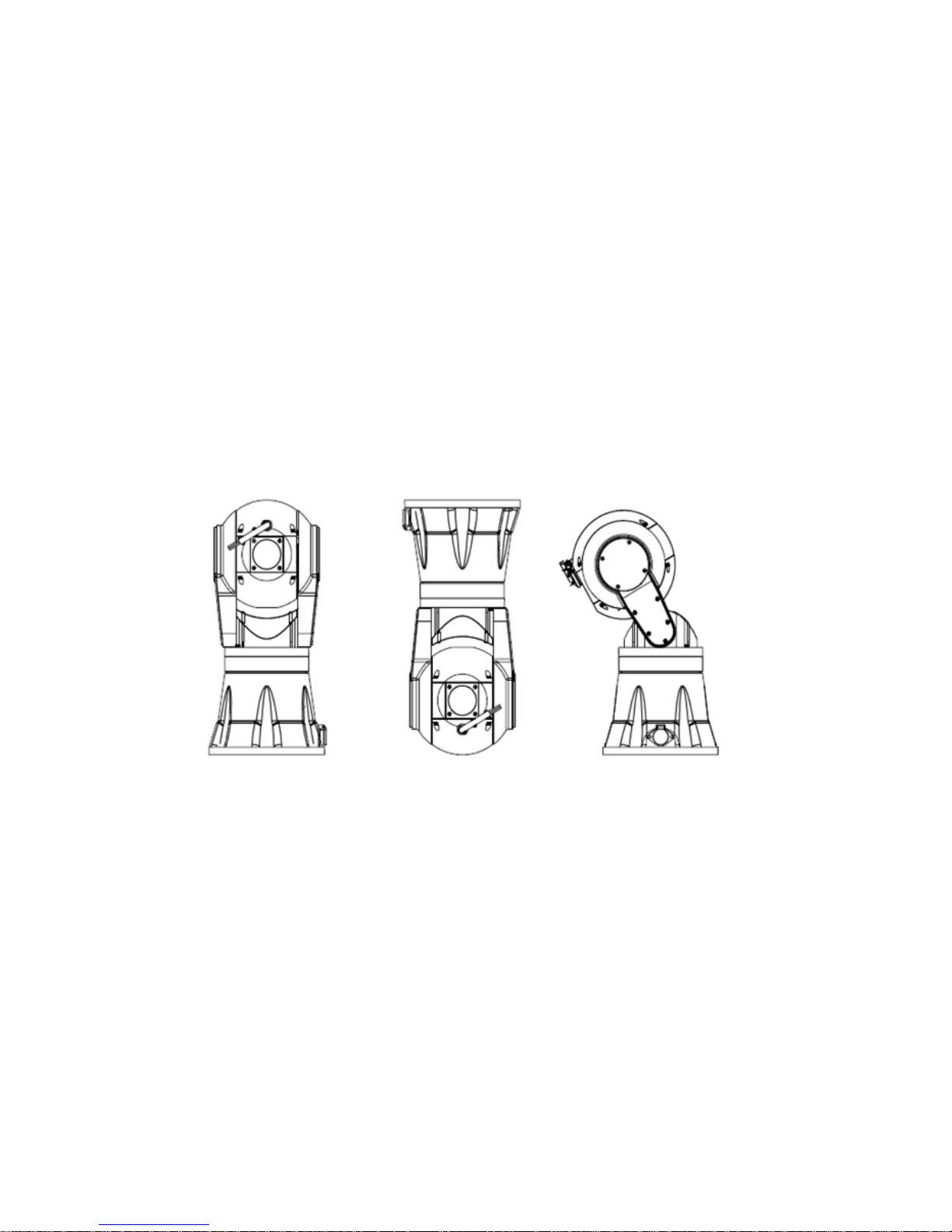
1.2 Appearance
pedestal stand mode in-ceiling mount installation pedestal with angle of 30°
1.3 Feature:
1.3.1 Function explanation:
z
The ball is made from aluminum alloy (thick: 5mm -15mm). It is firm and airproof
flat designed optical window uses toughened glass whose thickness is 5mm, and prevent distorted images with greatest
extend and protect the built-in integrated camera.
z 360° continuous pan rotation, 125° tilt rotation (new version)
z Multi installation way:pedestal stand mode and pedestal with angle of 30°, in-ceiling mount installation(camera with
an angel of 30° do not apply to in-ceiling installation )
z High reliability and the internal data will not lost after power cutoff

Pan/Tilt feature:
z Accurate step motor driving, smart operation, sensitive reaction and accurate orientation
z Manual control speed for pan: 0.1
0
~900/sec
z Manual control speed for tilt: 0.1
0
~400/sec
z Preset target speed: 90
0
/sec for pan, 400/sec for tilt
z Alterable auto scan speed: 1
0
~400 /sec can be set by the in-built menu
z Variable Apple peel scan speed: 1º-40º/sec for pan; 1º-20º/sec for tilt
z a pair of IR lamps available, more than 100meters of IR distance or laser lamp with distance of 300m(outdoor)
z Tilt rotation for pedestal stand mode:-35°~ +90° (0°for pan)
z Tilt rotation for pedestal with pitching angle of 30°: -65°~+90° (0°for pan)
z Tilt rotation for conversed mount: -35°~ +90° (0°for pan)
Camera Features:
z Built-in high resolution and variable high zoom camera module
z Black Light Compensation function
z Selectable Color or B&W image function
z Wide Dynamic Video function
z Image Stabilizer function
z Privacy mask function, can support up to 24 privacy zones
z Video Freeze function for high speed presets
Built in Decoder features:
z Integrated multi decoder controller: PELCO P/D protocol
z RS-485 feed back the orientation the pan& tilt
z Baud rate: 1200/2400/4800/9600b selectable
z Soft address and hard address are selectable
z Built-in function menu, the function of camera and pan/tilt can be set.
z Environment checking function, check the inside temperature real time;
z High reliability and the internal data will not lost after power cutoff
z Powering on self-restoring function: users can assign the camera
movement after powering on.
z Change speed proportionally function: Pan/tilt speed and
the depth of zoom lens decline proportionally and continuously
z The Pan/tilt orientation displays and camera zoom displays
variably. Data feedbacks the PTZ orientation.
z With pan auto scan function, the pitching angle can be set
z Virtual home position can be set
z With apple peel scan function
z 2 pattern function
z 4 presets tour function, dwell time can be set
z 255 preset positions with precision error less than ± 0.1
0
z 5 channels fixed time auto activate function, to run the preset movements
z 3 modes to control the wiper function

z Camera orientation display function(N,NE,E,SE,S,SW,W,NW total 8 orientations)
z 2 alarms input, 1 AUX output
OSD Menu Features:
z Built-in Chinese/English menu, easy to switch menu between 2 languages
z With OSD passport protect function
z Support Chinese/English input, can edit title of the user name, camera position and preset position
z Can set, run, clear presets, preset tours, privacy zone by menu
z Inside temperature and pan tilt orientation information display
Protect Features:
z Embed in surge and lightning protector
z Meeting IP66 standards, CE,ROHS, FCC standards
1.3.2 Function explanation
Screen menu function (OSD)
It has screen menu function. All information of camera and pan& tilt can be displayed by menu and to set the
function and parameter
Multi-camera control function
Select different camera only by mending dial switch setting, no any hardware or software needed. It supports
SONY, HITACHI cameras and so on.
Proportional pan
Horizontal and tilt speed change automatically with the zoom changes. When zooming wide, the camera speeds
down; then zooming narrow, the camera speeds up to catch better tracing effect.
Auto scan
Auto scan refers to the function of 360
0
continuous scan the images at certain speed on the horizontal lever when
keeping the pitching angle unchanged. The left and right limits can be set for continuous scan at certain speed on
the horizontal lever.
AUTO FLIP
When the camera tilts downward and goes just beyond the vertical poison, the dome rotates 180°. When the dome
rotates, the camera starts moving upward as you continue to hold the joystick in the down position. Once you let
go of the joystick after the dome rotates, joystick control returns to normal operation. The auto flip function is
useful for following a person who passes directly beneath the camera.
Preset
Any position of dome camera PTZ can be conserved. We call it preset (pre-established position). The preset can be
transferred and cleaned.
Preset tour
The dome camera will transfer pre- established preset 1-8 every 10 second. It will leap over to next preset position
if position in not among 1-8.
Pattern
The PTZ orientation move track of the camera can be stored, we call it pattern. The pan& tilt’s UP, DOWN, LEFT,
RIGHT and the lens’ FAR, NEAR can be stored. Also we can call the presetting. This function can be used to record
and simulate the operator’s operation process.

Zero test
The camera will turn to horizontal and tilt zero by preset 34 when the inevitable desynchronizing appears or the
operator wants to find zero position during working process. It can reset the orientation and is convenient for
operator
Low pharosage (colors/ black& white swift) function
The camera automatically changes CCD pharosage according to surrounding light. Color image changes to black&
white one in low pharosage; black& white image changes to color one in high pharosage.(related to camera)
Auto focus
The camera automatically adjusts lens focus to keep clear image if auto focus mode. Manually operate FAR or NEAR
focus adjustment can also adjust focus. The dome camera will recover auto focus adjustment function if operate
horizontal, vertical rotation or control lens zoom.
Auto iris function
The camera automatically adjusts iris to keep normal brightness in auto iris mode. Manually operate OPEN or
CLIOSE iris adjustment button can also adjust iris. The dome camera will recover auto adjustment function if operate
horizontal, vertical rotation or control lens zoom.
Backlight compensation
The object will become black as the shadow if strong light appears in background. Backlight compensation
function can compensate the brightness automatically to dark objects in bright light background and adjust the
brightness background to avoid the image full of brightness and get clear image. Too strong backlight can make
the object illegibility.
WDR (Wide Dynamic Range)
If there is quite dark and quite bright in the image, WDR can make the darkest and brightest balance to keep clear
image
Privacy Zone
Be sure protected zone be blocked when using the speed dome camera. The covered image moves with the
rotation of pan/tilt and varies with zoom, to keep the privacy zone covered.

Chapter 2 Notice proceeding of Installation
2.4 Safety Notice
2.5 Preparation of installation
2.6 Notice of installation
2.1 Safety Notice
Aim to guarantee user to use the product correctly and avoid danger or loss of property.
Defence measure is including two parts “Warning” and “Notice” as follows:
Warning: Ignoring warning may cause death or great damage.
Notice: Ignoring notice may cause damage or loss of property.
Warning remind user to defend potential
factor of causing death and great
damage
Noitce remind user to defend potential
factor of causing damage or loss of
property.
Warning
1, Completely according to the national or regional electric specification when installing and using the product.
2, Please using adapters from normal supplier.
Don’t connect multi cameras with one adaptor ( Exceeding the loading of adapter may generate excess heat or fire)
3, Turn off the power supply when connecing or dismantling the camera, never operate the dome camera with power.
4, Completely fix the speed dome camera when installing the item on wall.
5, If there is fume, fetor or noisy of the dome camera, please turn off power supply immediatly and pull out the cable;
And contact with our sales department right away.
6, If the camera can’t work normally, please contact with us and never dismantle it. (We are not responsible for any
unauthorized modification or dismantling.
Notice
Prior to installation and use of this product, the following WARNING should be observed. This product can be only
used in specified range in order to avoid any damage or danger.
z Installation and servicing should only be done by qualified service personnel;
z It can not be used in unqualified temperature( over 55℃ or below -40℃), high humidity ( otherwise firing may
be caused)
z Only use replacement parts recommended by us.
z After replacement/repair of this unit’s electronic components, conduct a resistance measurement by
multimeter to avoid short circuit or turnoff.
z Please use the soft cloth to clean the camera. Use neuter cleanser if bad smeared. No use the strong or corrosive
cleanser avoiding scuffing.
z The installation bracket should be capable of supporting five times the total weight of the integrated camera.
z Keep the product away from anti-magnet fied, make sure not to install it shook and impactive area, and never
let other objects fall on the product. (ignoring the tip may cause equirpment damage)
Please thoroughly read this manual prior to installation and operation.

2.2 Preparation of Installation
1, Basic requirement
1) All electric working must be accorded to latest electric, fire proof and related specification.
2) Be sure all accessories are included as packing list and application and installation way are as required. If not,
please contact with supplier.
3) Be sure the product is suitable for the working environment.
2, Check installation space.
Make sure there be enough space for the product and accessory.
3, Make sure the wall can afford 5 times of the speed dome camera and accessories.
4, Preparation of cable.
Using video cable according to transmitting distance. Specification of video coaxial cable is:
1) 75 ohm resistance
2) copper core cable
3) 95% copper shield.
2.3 Safety notice of installation.
1, Prior installation, read the instruction carefully.
2, To use the power supply and voltage as the label instruction of cable, standard voltage is
AC24V, DC12V 、DC24V
is available; Best voltage is
AC24V±10%. Long time excess high or low voltage will cause damage of speed dome camera.
Electric power must be kept over 50W, otherwise abnormal reset and control may occur.
3, Don’t aim the lens at high light object, otherwise CCD will abate and no image or image fuzzy.

Chapter 3 Notice proceeding of Installation
3.1 Pedestal stand mode
3.2 Wall stand mode
3.1 Pedestal stand mode
Remark: Installation of pedestal stand mode with pitching angle 30°, pedestal reversed
mode and pedestal stand mode is same.
3.1.1 Equipment list:
The mode of camera contains following parts. Inspect each package to make sure all parts are present.
Integrated high speed PTZ camera Power supply box
Camera body 1 pc
Connecting cable 1 pc
Manual 1 copy
Glove 1 pair
Power Supply box 1 pcs
M8×35 hexagonal Screw 6 pcs
Nut cap spanner 1 pc
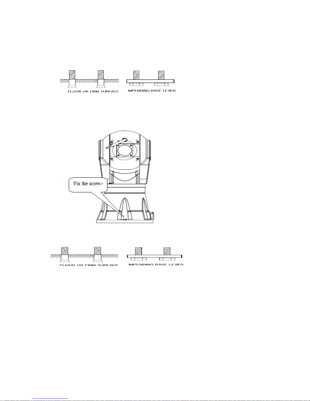
Steps of installation:
STEP 1 Locate the floor or impending base level that can support 5 times the weight of camera. Fix the bulgy snail
Φ8mm on the floor or firm surface.
STEP 2 Fix the camera body on the floor or impending base level
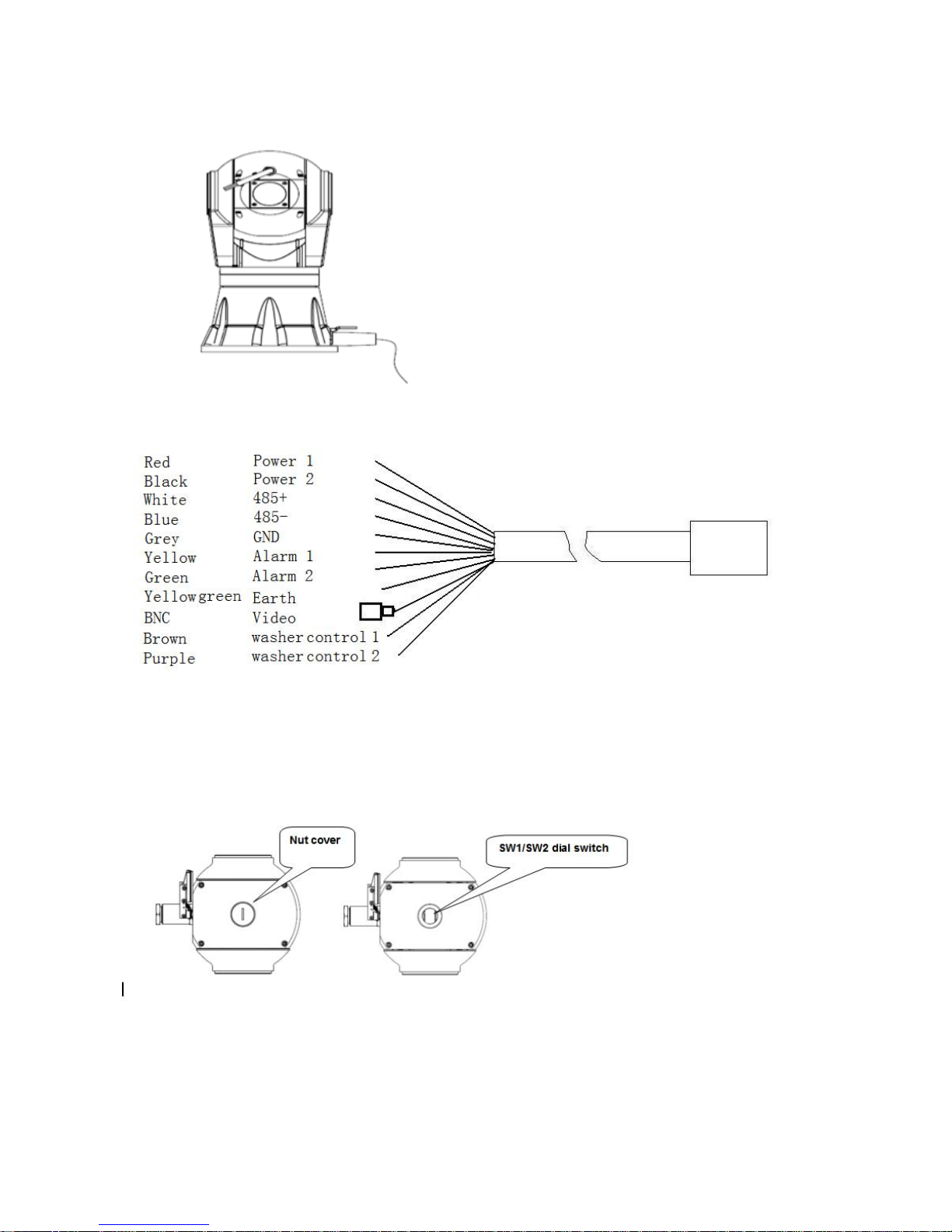
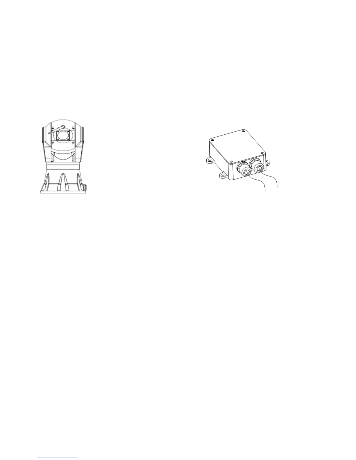
STEP 3 Put power supply, video output, RS485 control input wiring through waterproof connector plugs, and connect
them correspondingly to power supply, video, RS485 wiring of the connecting cable.
Remark: Cable can be from either side or bottom. Just take camera with cable from side for example
Connect the cable refer to the following picture:
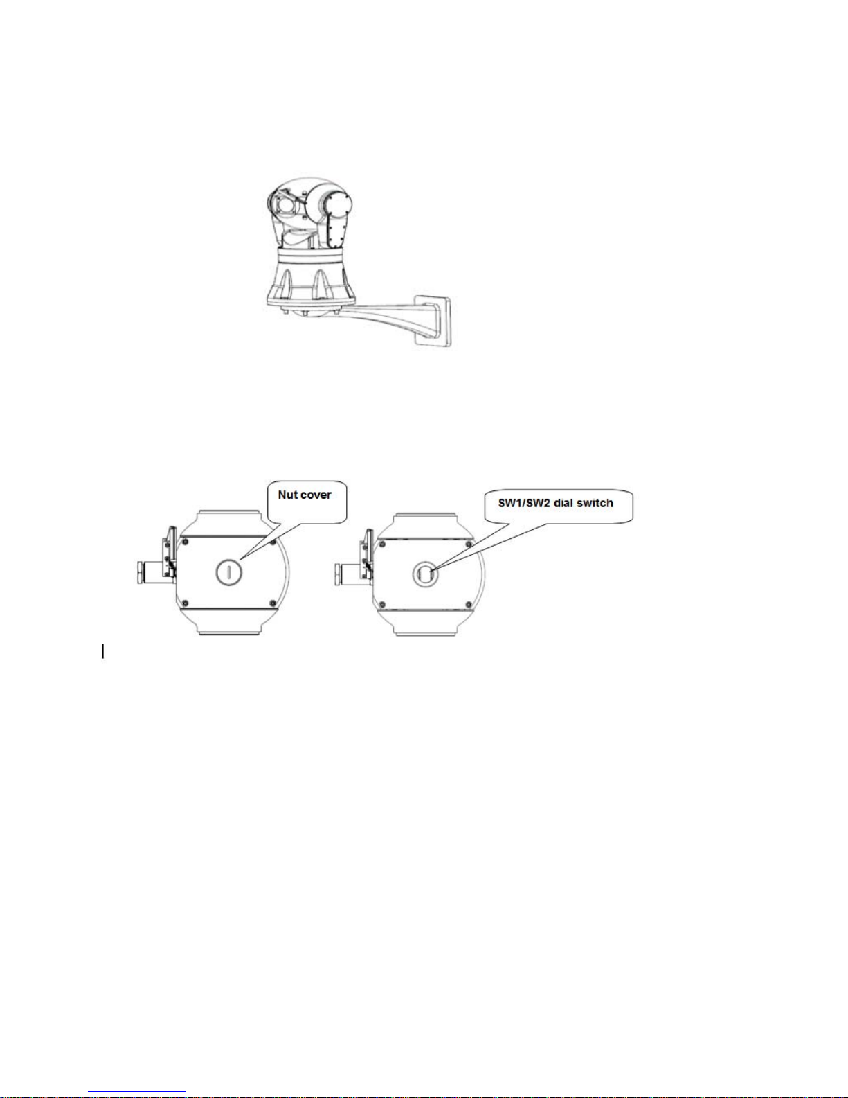
STEP 4 screws loose the nut cover on the camera, then you will see the 8 bit dial switch. Set the protocol, boud rate,
address for the camera making reference to Appendix 1. Screw tight the nut cover when finish setting.
STEP 5 Turn on the power after finishing check
3.2 Wall pedestal stand mode
Remark: Installation of pedestal stand mode with pitching angle 30° and pedestal stand mode is same.
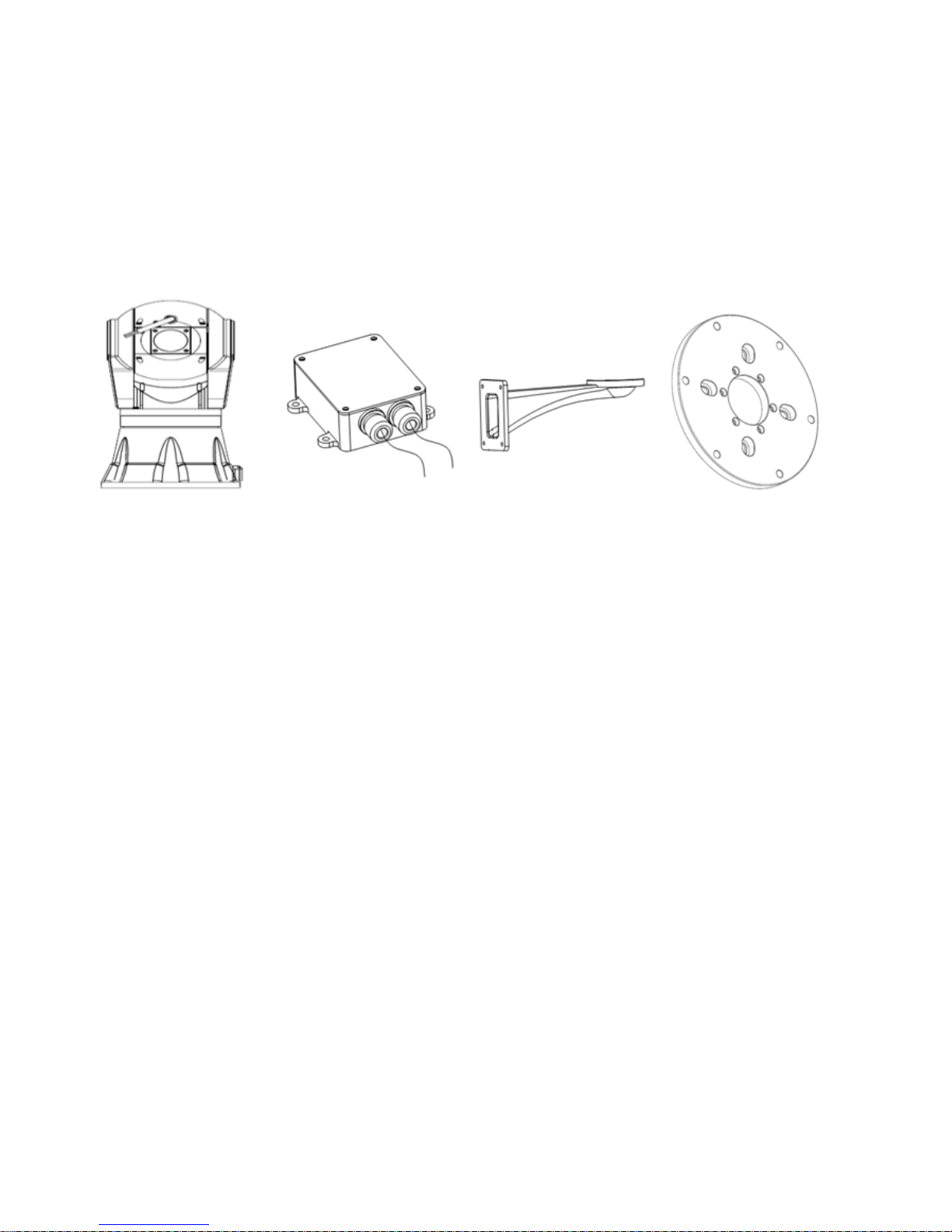
3.2.1 Equipment list:
The mode of camera contains following parts. Inspect each package to make sure all parts are present.
Integrated high speed PTZ camera Power supply box(undetermined) Wall mout bracket connecting tray
Camera body 1 pc
Connecting cable 1 pc
Wall mount bracket (choosable) 1 pc
Connecting Tray 1 pc
10. outer hexagonal wrench 1 pc
6. inner hexagonal wrench 1 pc
13. two-sides outer hexagonal wrench 1 pc
Manual 1 copy
Glove 1 pair
M8X35 inner Hexagon bolt 4 pcs
Power Supply box(undetermined) 1 pc
M8×35 Outer hexagonal screws 6 pcs
Nut cap spanner 1 pc
3.2.2 Steps of installation:
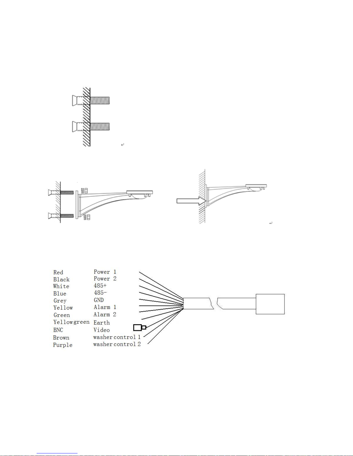
STEP 1 Locate the wall or impending base level that can support 5 times the weight of camera. Fix the bulgy snail
Φ8mm on the floor or firm surface.
STEP 2 If the power supply box is needed, fix the power supply box on the wall firstly, then fix the wall bracket on the
power supply box; If the power supply box is not needed, then fix the wall bracket on the wall directly.
STEP 3 Put power supply, video output, RS485 control input wiring through waterproof connector plugs, and connect
them correspondingly to power supply, video, RS485 wiring of the connecting cable.
Connect the cable refer to the following picture
STEP 4 Install the PTZ camera, insert the cables to the wall bracket, fix the bracket wall and connecting tray with 4pcs
M8 x 35 outer hexangular screws, and then fix the PTZ camera with connecting tray by M8 x 30 outer hexangular screws.
STEP 5 screws loose the nut cover on the camera, then you will see the 8 bit dial switch. Set the protocol, bound rate,
address for the camera. Screw tight the nut cover when finish setting.
STEP 6 turn on the power after finishing check

Chapter 4: TECHNICAL PARAMETER
4.1 Structure
4.2 Rotation Index
4.3 Electric Index
4.4 Camera module Parameter
4.5 IR lamps Parameter
4.1 Structure
●Integrated dome drive: aluminum-alloy
●Standard weight loading: 5KG
way of installation: pedestal mount wall mount, in-ceiling mount
the requirement for bracket :can stand more than 5 times the weight of camera
Net weight shipping weight
One without IR 12kg 14kg
One with IR 16kg 19kg
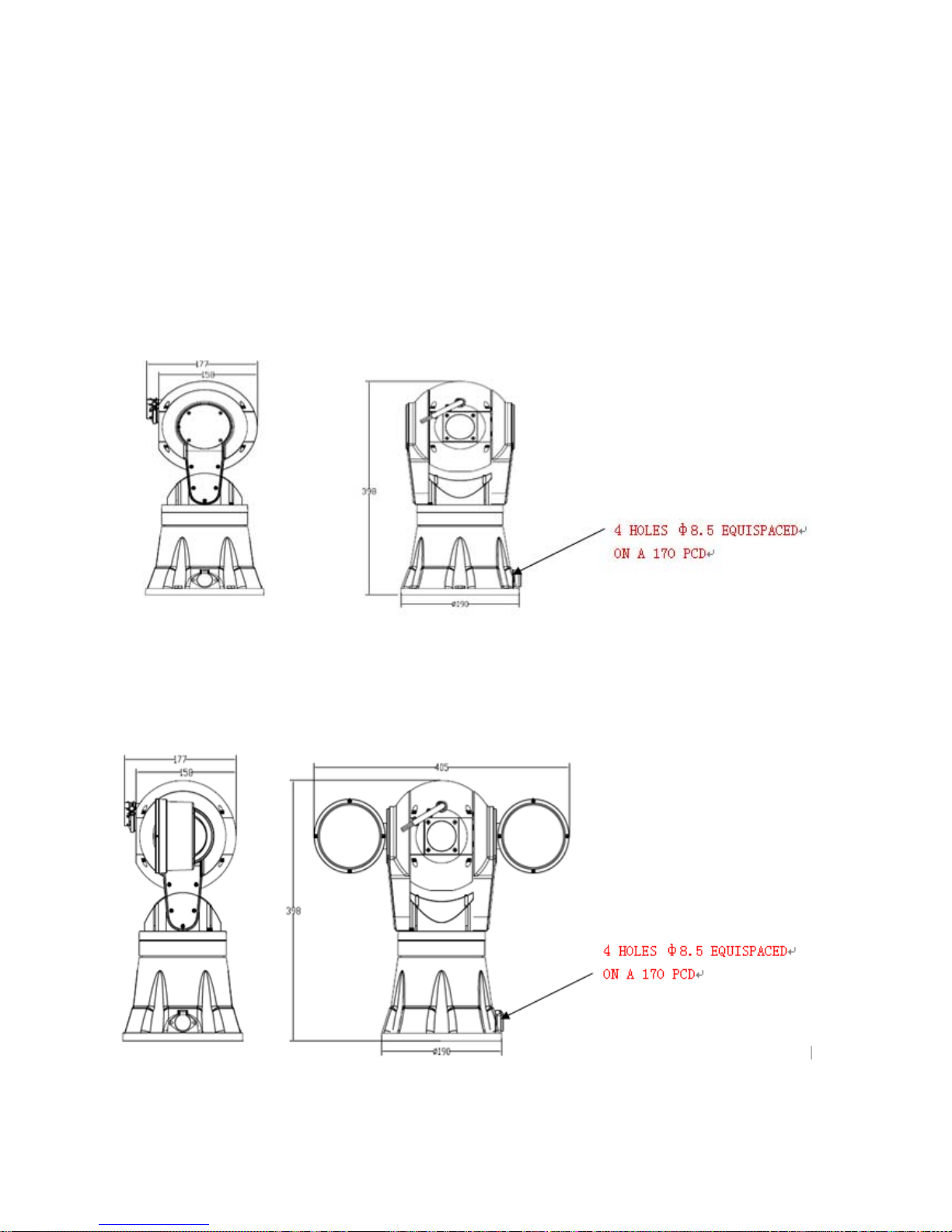
Dimension: see the following Dimension Drawing:
With IR lamps one:
●Operation Environment: indoor/outdoor
●working temperature: -40ºC ~55ºC(outdoor)
 Loading...