

oxic XD-S16200 User Manual
1
MULTI-CHANNEL
DIGITAL VIDEO RECORDER
Version 92040729

2
Introduction
This manual is for the users who attempt to use Multi-channel Digital
Video Recorder (MDVR). It illustrates features, installation guide, connecting to
peripherals, and Graphic User Interface (GUI) operation. Please familiarize
yourself with the contents in this manual before using the DVR. Make sure that
you have referred to an expert when opening the outer case for repair or
installing HDD. If you have any inquiries or questions on the products, please
consult to your local dealer.
When you have received your new MDVR system, inspect the contents of the
package to verify that all units have been shipped before you begin the
installation process.
Caution Several connectors on the rear panel of the MDVR system are keyed
and must be properly aligned before inserting them into the port. Failure to
align the plug can damage connector’s functionality.
3
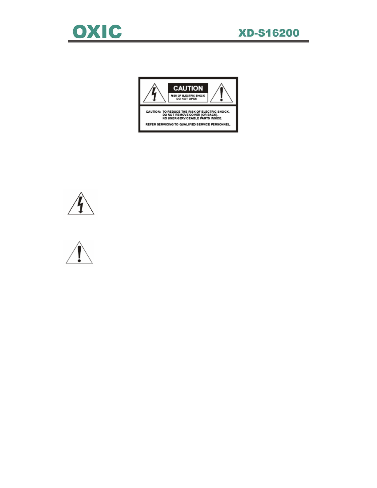
Caution
WARNING
To prevent fire or electric shock, do not expose this product to rain or moisture.
Dangerous high voltages are present inside the enclosure. Do not open the
cabinet. Refer servicing to qualified personnel only.
The lightning flash with arrowhead symbol, within an equilateral
triangle, is intended to alert the user to the presence of un-insulated
“dangerous voltage” within the product’s enclosure that may be of
sufficient magnitude to constitute a risk of electric shock to persons.
The exclamation point, within an equilateral triangle, is intended to
alert the user to the presence of important operating and
maintenance (servicing) instructions in the literature accompanying
the appliance.

4
About This Product
USA
This product has been tested and found to comply with the limits of a Class A
computing device pursuant to part 15 of the FCC rules, which are designed for
reasonable protection against harmful interference when operated in a
commercial environment.
Europe CE
This product adheres to the requirements for radiated emission according to
the limits of the European Standards.
Liability
This manual has been taken every care for user when preparation. If user
detected any inaccuracies or omissions, please contact your local vendor for
more information.
Legal Consideration
Camera surveillance may be against the laws that vary from country to country.
Please check the laws in your local region before using this product for
surveillance purpose.
Electromagnetic Compatibility (EMC)
This product can generate and radiate radio frequency energy, and if not
installed or used followed by the instruction manual, may cause interference to
radio communications. Operation of this product in a residential area is likely to
cause interference, in which case the user will be required to take whatever
measure and cost to correct the interference. To ensure compliance with EMC,
shielded cables should be required to use with this product.

5
Table of Contents
Chapter 1 Products Overview 9
1.1 Unpacking...........................................................................................9
1.2 DVR Overview .................................................................................. 11
1.2.1 DVR Functions and Features ................................................. 11
1.2.2 DVR Front Panel.....................................................................12
1.2.3 DVR Rear Panel ..................................................................... 13
1.3 Multi-Keyboard Overview..................................................................14
1.3.1 Keyboard Front Panel.............................................................14
1.3.2 Keyboard Rear Panel .............................................................15
1.4 Remote Controller.............................................................................16
Chapter 2 Hardware Installations with DVR 17
2.1 Cautions in Installation...................................................................... 18
2.2 HDD Installation................................................................................19
2.3 Multi-Keyboard & MDVR Connections.............................................. 20
2.3.1 Single Multi-Keyboard with Single MDVR Connection............20
2.3.2 Single Multi-Keyboard with Multiple MDVRs Connection........20
2.3.3 Multiple Multi-Keyboards with Single MDVR Connection........21
2.3.4 Multiple Multi-Keyboards and MDVRs Connection .................21
2.4 Video Output Connection.................................................................. 23
2.4.1 Connect with CCTV Monitors .................................................23
2.4.2 Connect with TV .....................................................................23
2.4.3 Connect with CRT or LCD Monitors........................................24
2.5 Network Installation...........................................................................25
2.5.1 Connect with DVR ..................................................................25
2.5.2 Setup LAN Configuration in DVR Main Manu .........................25
2.6 Cameras Installation .........................................................................26
2.6.1 Connect with Cameras ...........................................................26
2.6.2 Setup RS-485 in Main Menu to Control Cameras................... 26
2.6.3 Setup Camera ID & PTZ Camera Enable in DVR Main Menu 27
2.6.4 PTZ Camera Control...............................................................28
2.6.5 Set Preset for PTZ Camera ....................................................29
2.6.6 Goto Preset ............................................................................30
2.6.7 Setup Camera Adjust in DVR Man Manu................................31
2.6.8 Setup Camera Action in DVR Main Manu...............................32
2.6.9 Setup Camera Title in DVR Main Manu .................................. 33
2.6.10 Setup Sequence Time in DVR Main Manu ...........................34

6
2.7 Alarm Setup ......................................................................................35
2.7.1 Connect with Alarm Devices...................................................35
2.7.2 Connecting to DVR ................................................................. 36
2.7.3 Setup Respondent Cameras for Alarm in DVR Main Menu ....37
2.7.4 Setup Alarm Out Enable in DVR Main Menu ..........................38
2.7.5 Setup Alarm In Type in DVR Main Menu ................................40
2.7.6 Setup Alarm Response in DVR Main Menu............................43
2.7.8 Setup Alarm List in DVR Main Menu.......................................45
2.7.9 Setup Motion in DVR Main Menu ...........................................46
2.7.10 Setup Alarm/Motion Setup in DVR Main Menu .....................47
Chapter 3 Basic Operations 48
3.1 Single Screen ...................................................................................48
3.2 Single Screen with Zooming .............................................................49
3.3 Display Screen..................................................................................50
3.4 Sequencing Screen ..........................................................................53
3.5 Main Menu Screen............................................................................54
3.6 List Screen........................................................................................55
3.7 Help Screen ...................................................................................... 58
3.8 Playback Screen...............................................................................59
3.9 Freeze...............................................................................................60
3.10 Keyboard Lock................................................................................60
Chapter 4 Menu Setup 62
4.1 Main Menu Overview ........................................................................62
4.1.1 Menu Tree ..............................................................................64
4.2 Camera.............................................................................................65
4.2.1 Camera Adjust ........................................................................67
4.2.2 Camera Action ........................................................................68
4.2.3 Camera Title ...........................................................................69
4.2.4 Camera Sequence Time.........................................................70
4.3 Display and Language ......................................................................71
4.3.1 Screen Center Point & Size ....................................................71
4.3.2 Date/Time Position .................................................................72
4.3.3 Camera Title Type...................................................................73
4.3.4 Date/Time Display ..................................................................74
4.3.5 Clock Mode.............................................................................75
4.3.6 Anti-Flicker..............................................................................76
4.3.7 Test Pattern.............................................................................77
4.3.8 Language................................................................................78

7
4.4 Record ..............................................................................................79
4.4.1 Record Setup..........................................................................79
4.4.2 Frame Rate.............................................................................81
4.5 Alarm/Motion Setup ..........................................................................84
4.5.1 Alarm In Event ........................................................................84
4.5.2 Alarm Out Enable.................................................................... 85
4.5.3 Alarm In Type.......................................................................... 87
4.5.4 Alarm Response .....................................................................88
4.5.5 Alarm List................................................................................90
4.5.6 Motion Setup ..........................................................................91
4.5.7 Alarm/Motion Enables.............................................................93
4.6 Schedule...........................................................................................93
4.7 Installer Setup...................................................................................96
4.7.1 Date/Time Setup.....................................................................96
4.7.2 LAN Setup ..............................................................................97
4.7.3 RS-485 Setup .........................................................................98
4.7.4 Camera ID Setup....................................................................99
4.7.5 Password Setup ...................................................................100
4.7.6 Password Management ........................................................101
4.7.7 Auto Demo............................................................................103
4.7.8 Make Boot Disk.....................................................................104
4.7.9 Compress Information ..........................................................105
4.8 System Information.........................................................................107
4.8.1 DVR ...................................................................................... 107
4.8.2 Disk.......................................................................................108
4.8.3 Video Size ............................................................................109
4.9 Save/Load Configurations............................................................... 110
4.9.1 Save/Load ............................................................................ 110
Chapter 5 System Operation 111
5.1 How to Set Recording..................................................................... 111
5.1.1 Sample System Configuration .............................................. 111
5.1.2 Schedule Setting................................................................... 113
5.1.3 Alarm In and Alarm Out Setting ............................................ 114
6.1.4 Motion Detection Setting....................................................... 116
5.1.5 Frame Rate, Quality, and Recording Time Setting................ 117
5.1.6 Enable Recording ................................................................. 119
5.1.7 Check Recording .................................................................. 120
5.2 How to Estimate Recording Time....................................................121

8
5.3 Image Backup System ............................................................... 122
5.3.1 CF Card Backup System.................................................122
Chapter 6 Trouble Shooting 126
6.1 Installation.......................................................................................126
6.1.1 The DVR is not power on......................................................126
6.1.2 Power is on, but the DVR dose not operate..........................126
6.1.3 Images are not showing on the monitor................................126
6.1.4 The picture quality on the monitor is poor.............................126
6.2 Recording .......................................................................................127
6.2.1 The DVR will not start recording ...........................................127
6.2.2 The DVR can not perform alarm recording ...........................127
6.3 Playback ......................................................................................... 127
6.3.1 The DVR can not perform playback......................................127
6.4 Others.............................................................................................127
6.4.1 The DVR will not detect motion.............................................127
Appendix A: Specifications 128
Appendix B: Recording Time and HDD Space 131
Appendix C: Glossary 132
9
Chapter 1 Products Overview
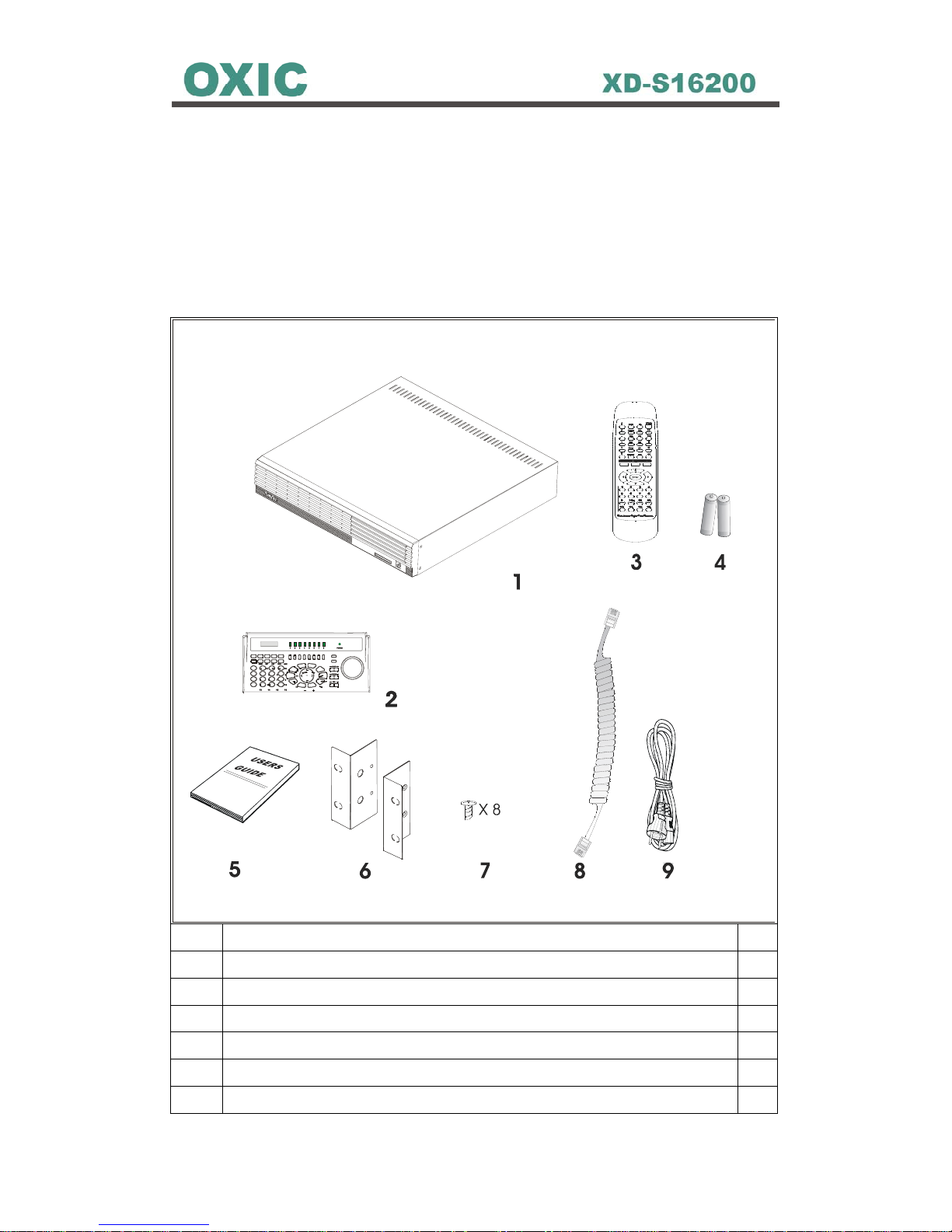
1.1 Unpacking
Please place the product on a flat surface to inspect if there is any part
missing among the following items list.
Item Name and Description Pcs
1 Mainframe *1
2 Front Keyboard *1
3 IR Remote controller *1
4 AAA NO.4 Battery: for IR Remote controller *2
5 User’s Manual *1
6 Rack Mount Ears *2

10
7 RS-485 Cable 40 CM: used to connect Mainframe and Front
Keyboard
*1
8 AC Power Cord *1
9 IDE Cable 40CM *2
Note: If there any part is missing or damaged, please contact your local vendor
as soon as possible.

11
1.2 DVR Overview
1.2.1 DVR Functions and Features
Key Features:
z Reliable and Stable Stand-Alone System
z Individual Unit Accommodates 8/16 Camera Inputs
z Simultaneous Real-Time Recording, Live Images, Playback and
Networking
z MPEG2-Like and JPEG Compression Algorithms
z 16 Alarm Inputs, 4 Alarm Outputs And 1 Relay Output
z Programmable Recording Schedule and Frame Rate Setting
z High-Speed Searching by Time or Events
z Remote Viewing, Access and Control via LAN/WAN/INTERNET
z Support Various PTZ Cameras
z Support RAID Disk (Option)
z CF Card Backup Mode
z Remote 16-Channel Playback
z Evidence Preservation Lock
12
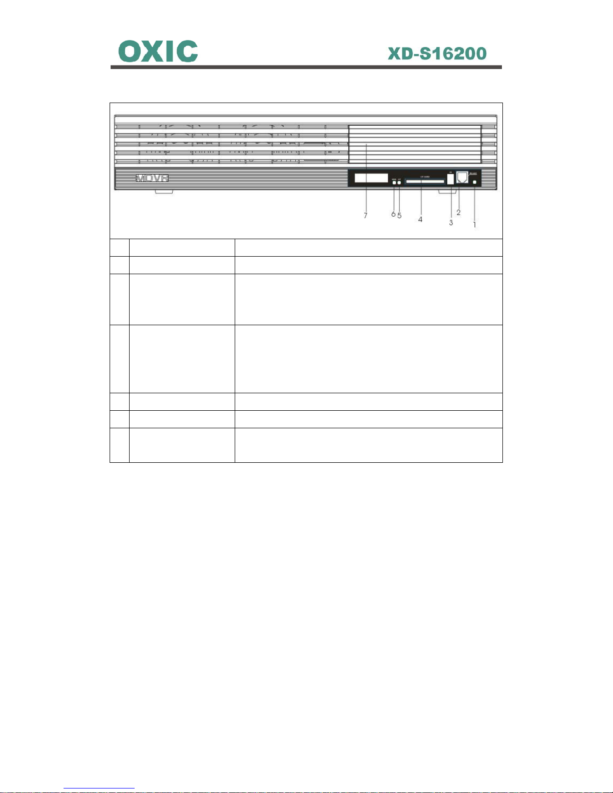
1.2.2 DVR Front Panel
1 Power Indicator This light Indicates the power status of the DVR.
2 RS-485 Connector This port is a socket for RS-485 of front keyboard..
3 IR Receiver This receiver is for infrared remote controller,
NOTE: keep the receiver from disturbs for IR remote
controller.
4 Compact Flash (CF)
Card Socket
This socket is for user inserting a CF Card to backup
files from HDD or internal CF Card.
NOTE: Please don’t remove CF Card while power
on.
5 CF Card Indicator This light Indicates the CF card status of the DVR.
6 HDD Indicator This light Indicates the HDD status of the DVR.
7 Reserved CDRW /
DVDRW Socket
Only Advanced Model will come with
CDRW/DVDRW driver.
13
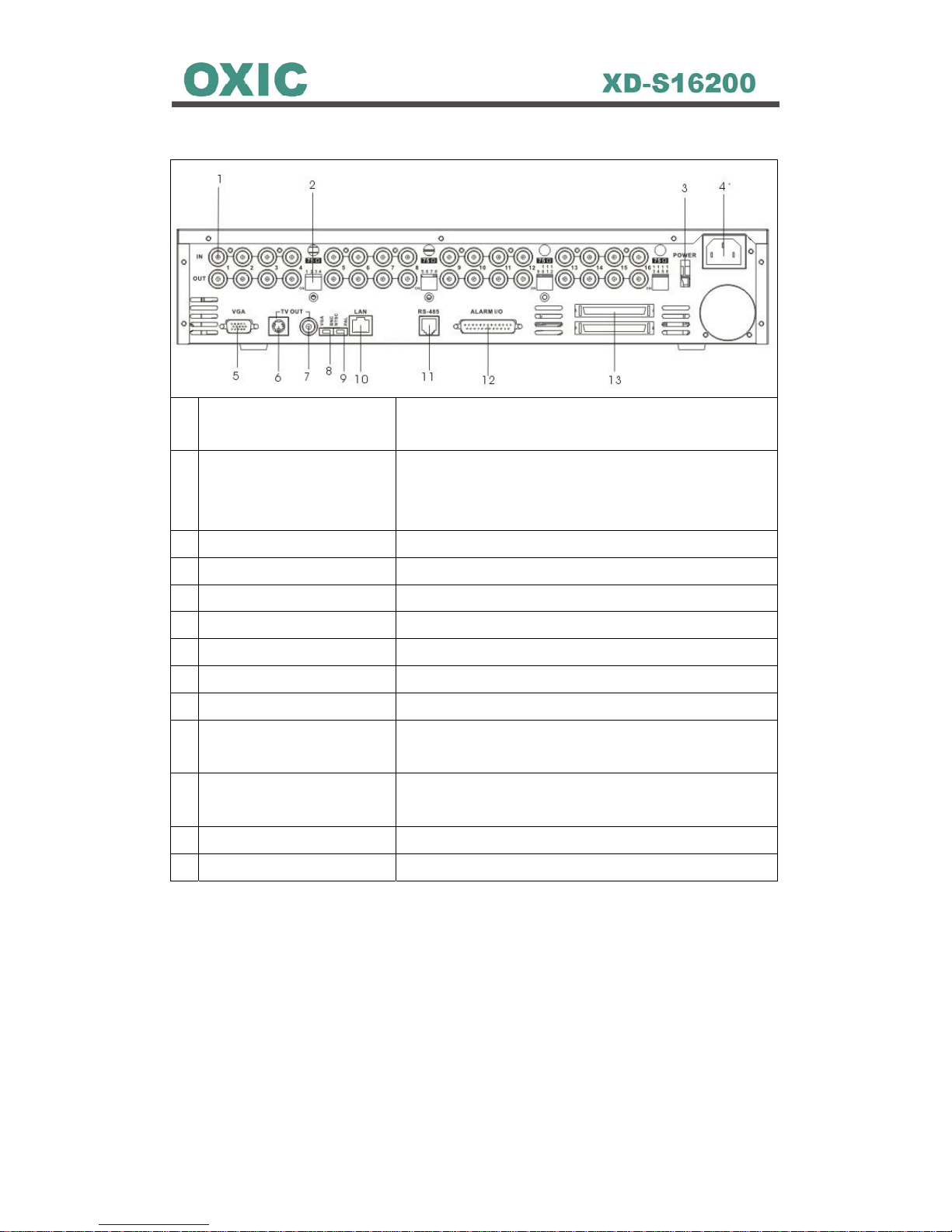
1.2.3 DVR Rear Panel
1 Video-In Looping and
Video-Out Connector
This BNC connector is used to connect a camera
or video output of another DVR.
2 Dipswitch This dipswitch sets Video Looping Terminal
Resistor.
Note: Set ON, if there is no video looping.
3 Power Switch This button sets power ON or OFF.
4 Power Core Connector Power Core input.
5 VGA Out Connector Provides VGA signal.
6 S-Video Out Connector Provides S-Video signal.
7 BNC Out Connector Provides a composite video signal.
8 VGA/BNC Switch Switch VGA or BNC.
9 NTSC/PAL Switch Switch NTSC or PAL
10 LAN Port Connector Provides a standard RJ-45 socket for 10/100
Mbps Ethernet networks.
11 RS-485 Port Connector This socket is a RJ-11 connector. It provides a
RS-485 control signal port.
12 ALARM I/O Connector Receives/Provides alarm I/O signals.
13 IDE RAID Connector (Optional). IDE RAID connector port.
14
1.3 Multi-Keyboard Overview
The Multi-Keyboard is designed for User(s) more conveniently to control the
MDVR(s).
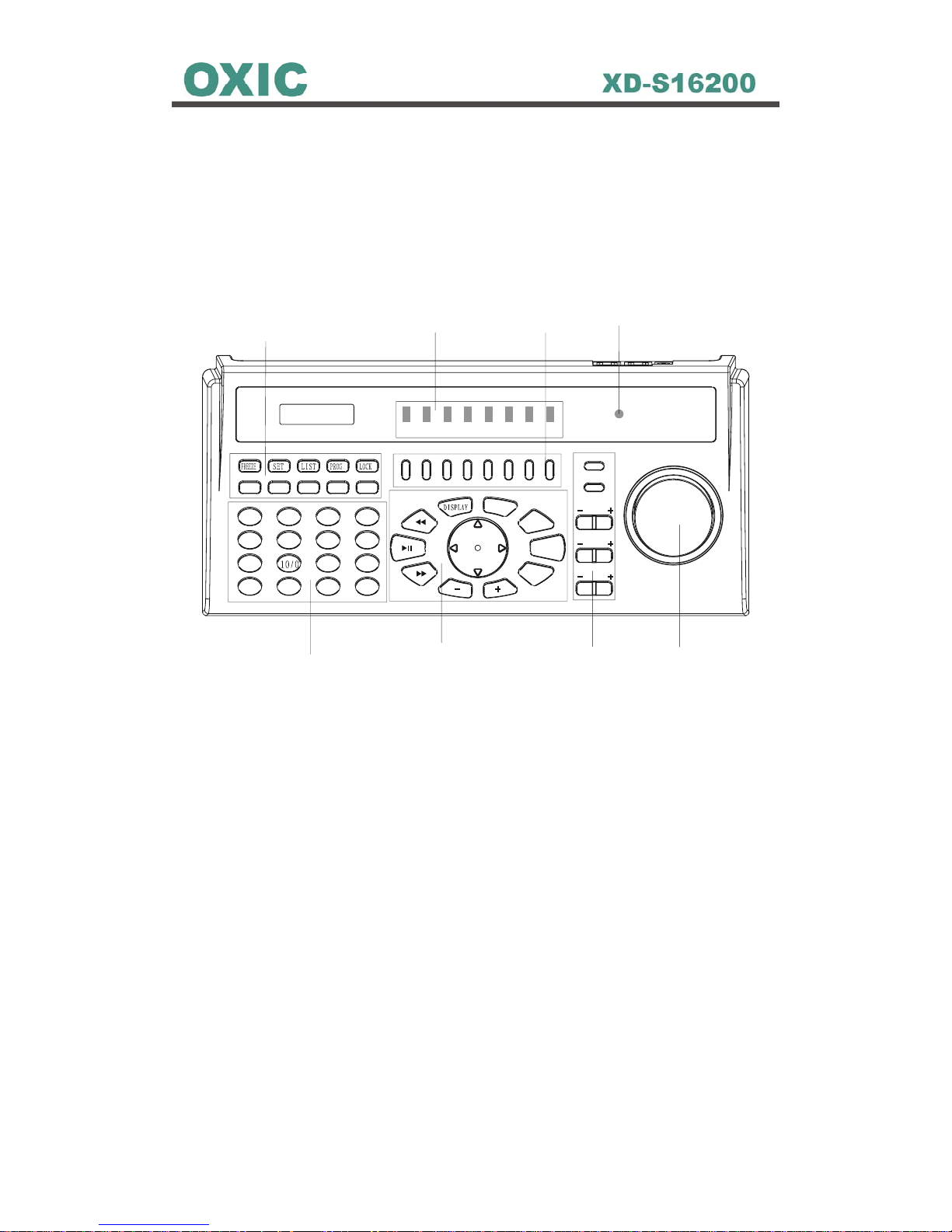
1.3.1 Keyboard Front Panel
F1 F2
F3
F4
F5
ENTER
ESC
M
E
N
U
SEQ
12
3
4
5
678
9
11 12
13
14
15 16
ZOOM
IRIS
F
OCUS
SET PRESET
GOTO PRESET
P
OWER
1234
5678
1
2
3
4
5
6
7
8
1. Power Indicator
2. DVR ID Buttons
3. DVR ID Indicators
4. Keyboard control Functions
5. Channels Control Buttons
6. Playback Control Buttons
7. PTZ Cameras Control Buttons
8. Encoder
15
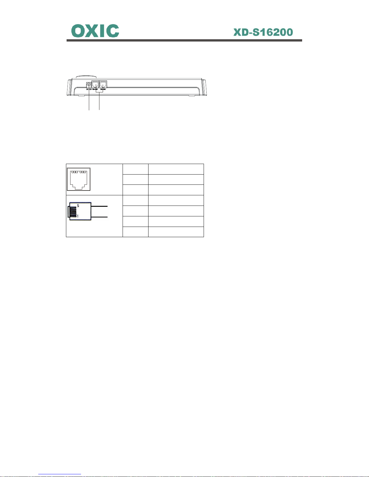
1.3.2 Keyboard Rear Panel
1
2
1. Power Cord Jack
2. RJ11 Connector (for RS485)
Pin no Pin define
1 No Connected
123 456
2 DC +12V
3 GND
4 DATA A (+)
5 DATA B (-)
6 No Connected

16
1.4 Remote Controller
1
Provide basic function operations.
2 Replace the Keyboard encoder Knob.
3
Basic operation keys.
4 Alarm key. Press this button to trigger
alarm signals to the DVR.
5
Provide playback operation.
6
Function keys for setting menu
7
Function keys for setting menu
8
Select video channel directly.
17
Chapter 2 Hardware Installations with DVR
18
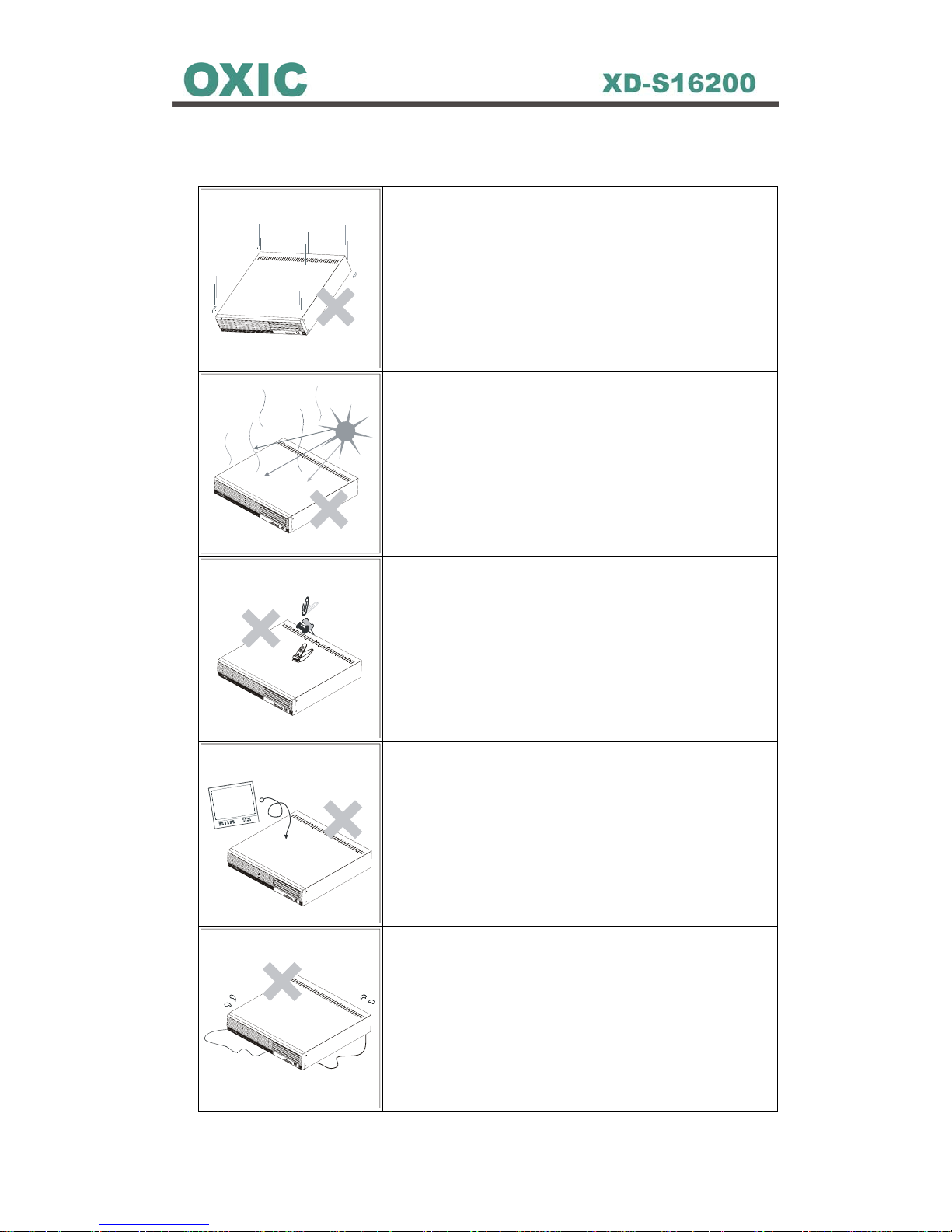
2.1 Cautions in Installation
Severe impact or vibration may cause malfunction.
Avoid a direct ray of light, and keep the safe
distance between crowded place and the product
as well as its assemblies.
Be careful not to insert any conducting material in
the ventilation space of product.
Avoid places with strong magnetic or electrical
field, or places near a radio or TV.
Always keep the place dust-free when installing or
moving DVR.
19
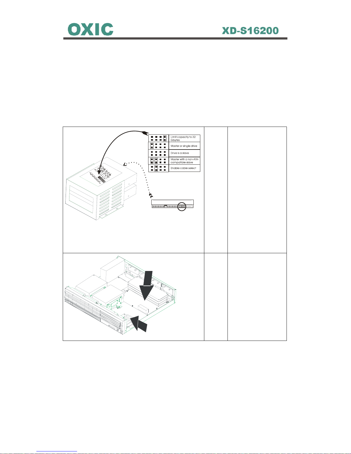
2.2 HDD Installation
To install Hard Disk for DVR, make sure turn off the power switch of the DVR
rear panel and pull off the power plug from the socket first. Afterward using
cross screwdriver removes all screws around the case to open the DVR’s
upper case, and then follow the three steps below to install the Hard Disk for
DVR.
STEP 1 Set IDE selectable
jumper correctly as
default
configuration on the
HDD before
installation. (It must
refer to HDD user
guide)
Please note the one
is set to Master, the
other one is Slave,
and no HDD brand
is limited.
IDE So c k et f o r HDD2
H
D
D
1
H
D
D
2
IDESocket for H
DD1
STEP 2 Use IDE Cables to
connect with HDDs
and IDE sockets.
20
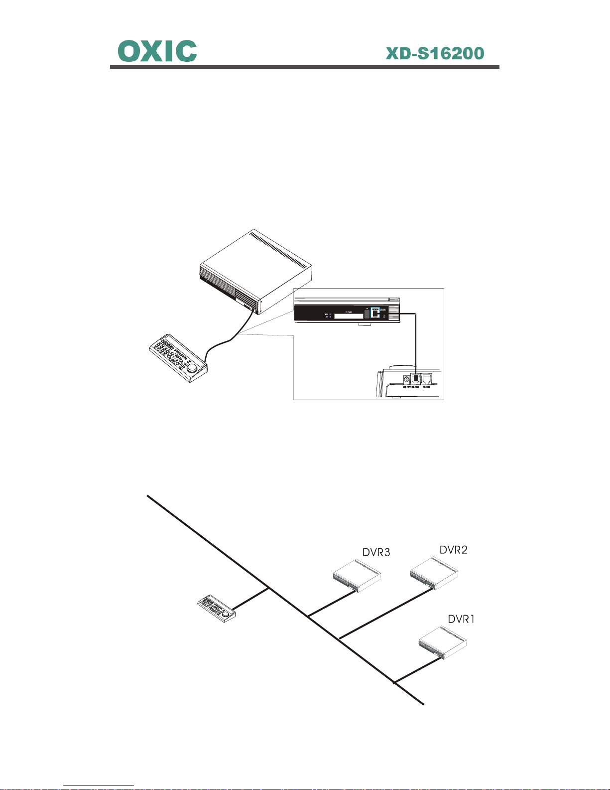
2.3 Multi-Keyboard & MDVR Connections
Use Multi-keyboard RS-485 port to connect MDVR’s front RS-485 port. There
are 4 variable connections for MDVR(s) and Multi-Keyboard(s):
2.3.1 Single Multi-Keyboard with Single MDVR Connection
2.3.2 Single Multi-Keyboard with Multiple MDVRs Connection
R
S
4
8
5
B
U
S
-
Multi Keyboard
-
.
.
.
.
.
DVR8
123456
21
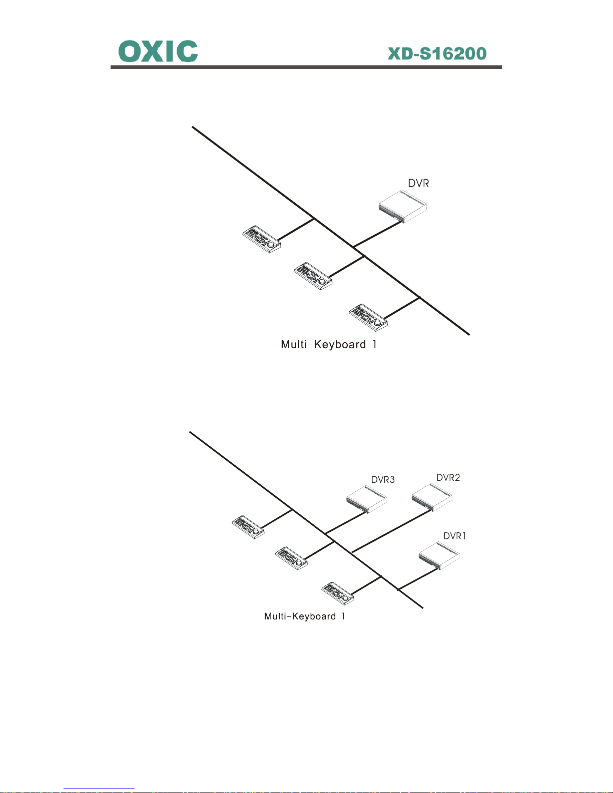
2.3.3 Multiple Multi-Keyboards with Single MDVR Connection
Multi Keyboard
-
2
R
S
4
8
5
B
U
S
-
Multi Keyboard
-
3
.
.
.
.
Multi Keyboa rd 8
-
2.3.4 Multiple Multi-Keyboards and MDVRs Connection
Multi Keyboard
-
2
R
S
4
8
5
B
U
S
-
Multi Keyboard
-
3
.
.
.
.
Multi Keybo a rd 8
.
.
.
.
.
DVR8
22
2.3.5 Multi-keyboard with Multiple DVRs ID Setup
While user tries to control multiple DVRs to do different job, user must set up
each connected DVRs’ different ID in Main Menu first.
To set up DVR’s ID for keyboard, simply go to the Main menu path:
Main Manu Æ Installer Setup Æ RS-485
Figure 2.3.5: DVR ID Setup
Use to move cursor for selecting the ID section. Press
PROG
key for 3
seconds and use
-
+
to set up DVR ID number (0~7). Then, press
PROG
key for 3 seconds again and press the keyboard ID key (1~8) (the buttons
below the LEDs numbers on the keyboard).
NOTE: The MDVR ID number 0~7 are with corresponding Keyboard ID 1~8. For
example, if set DVR ID is 5, then press keyboard ID button number 4.

23
2.4 Video Output Connection
Video output connection ports all are on the DVR’s rear panel.
2.4.1 Connect with CCTV Monitors
Use standard “TV Out” BNC Port on the DVR real panel
1. Video
2. Ground
2.4.2 Connect with TV
Use standard S-Video Port
1
2
4
3
1. C Ground
2. C (Chrominance)
3. Y Luminance + Sync
4. Y Ground
1
2
24
24
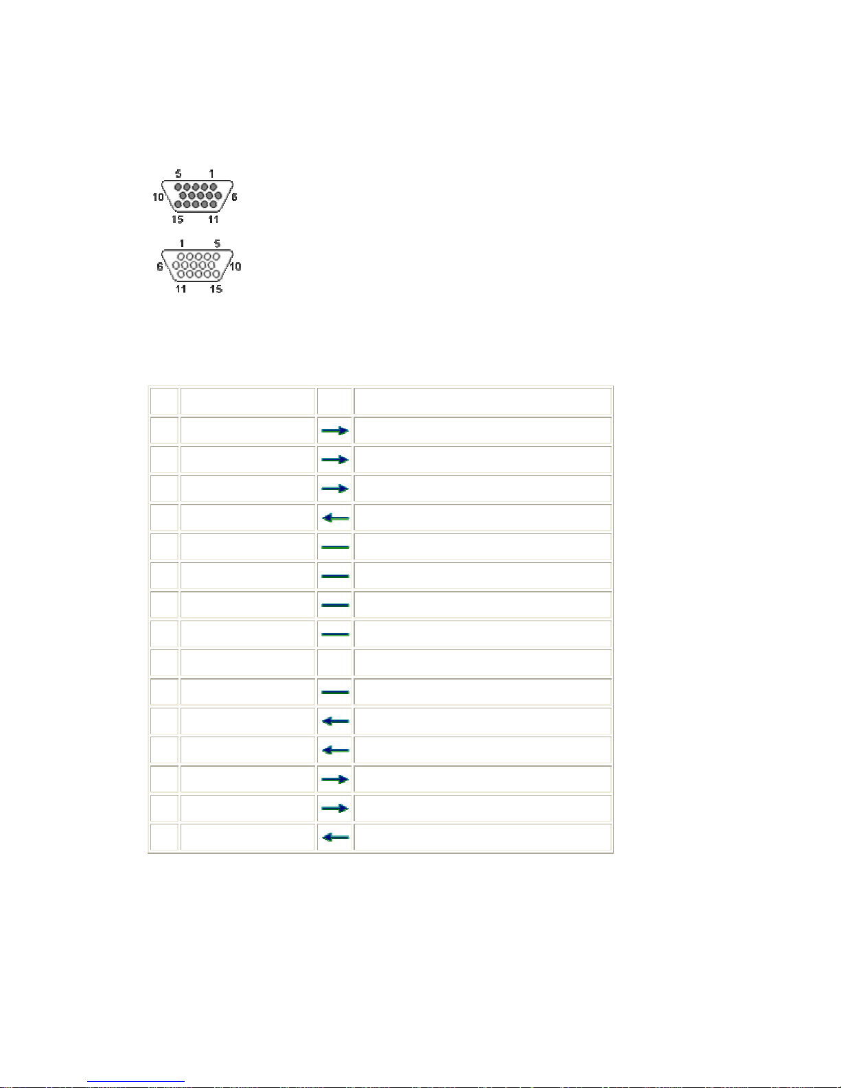
2.4.3 Connect with CRT or LCD Monitors
Use standard VGA Port
(At the DVR)
(At the monitor cable)
z 15 PIN HIGHDENSITY D-SUB FEMALE at the DVR.
z 15 PIN HIGHDENSITY D-SUB MALE at the monitor cable.
Pin Name Dir Description
1 RED
Red Video (75 ohm, 0.7 V p-p)
2 GREEN
Green Video (75 ohm, 0.7 V p-p)
3 BLUE
Blue Video (75 ohm, 0.7 V p-p)
4 ID2
Monitor ID Bit 2
5 GND
Ground
6 RGND
Red Ground
7 GGND
Green Ground
8 BGND
Blue Ground
9 KEY - Key (No pin)
10 SGND
Sync Ground
11 ID0
Monitor ID Bit 0
12 ID1 or SDA
Monitor ID Bit 1
13 HSYNC or CSYNC
Horizontal Sync (or Composite Sync)
14 VSYNC
Vertical Sync
15 ID3 or SCL
Monitor ID Bit 3
25
25
2.5 Network Installation
2.5.1 Connect with DVR
Use RJ-45 port on the DVR’s rear panel to connect with network. Network
function provides user to remote view the DVR’s image on a PC by the
NetView application. To install the Network for DVR, please insert the LAN
cable into RJ-45 port on the DVR rear panel.
LAN Connector
1234 5678
LED1
LED
2
The pin-out of the RJ-45 jack is the same as a standard
Ethernet UDP jack.
LED1: YELLOW LIGHT Indicates the MESSAGE
Transaction.
LED2: GREEN LIGHT Indicates the LAN PORT ON LINE.
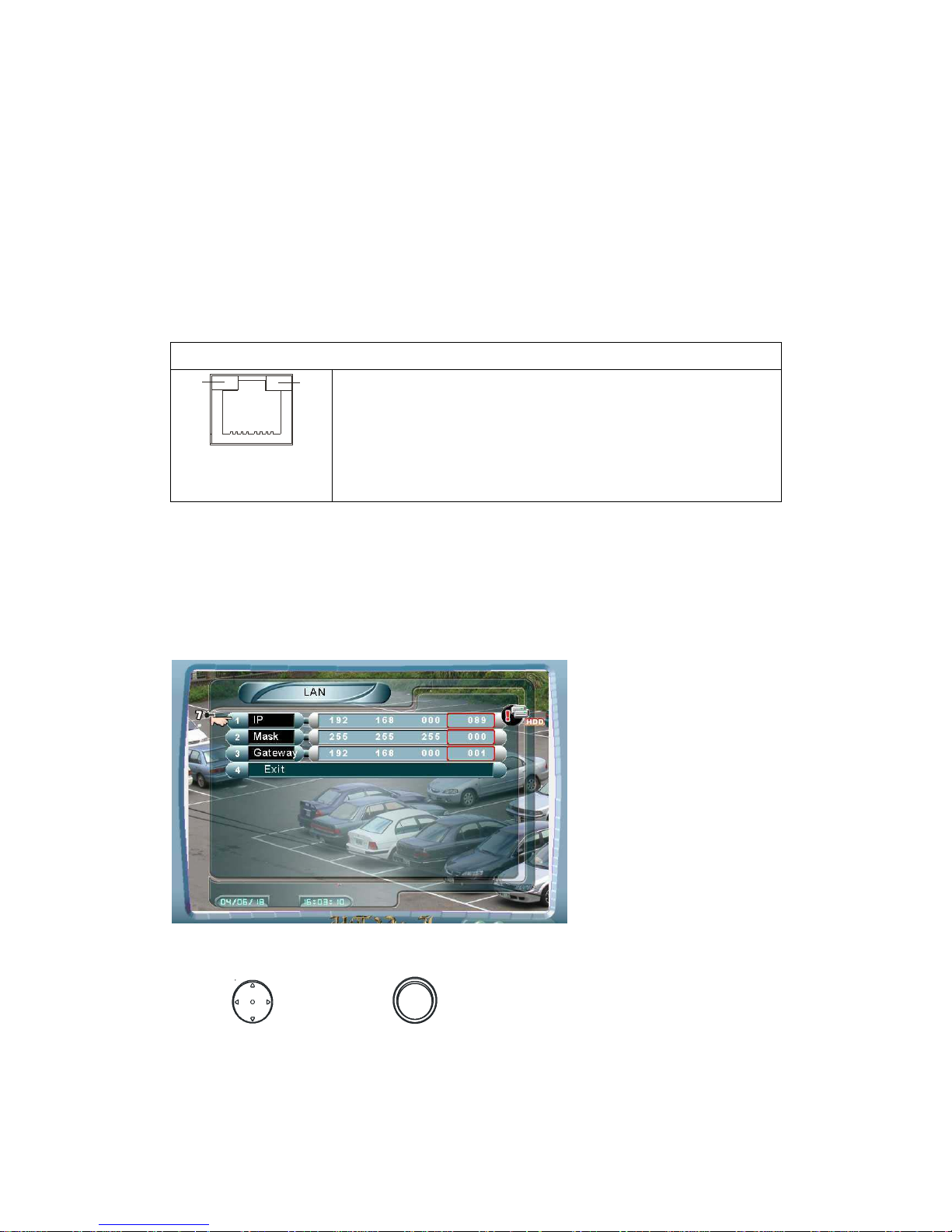
2.5.2 Setup LAN Configuration in DVR Main Manu
1. Go to the path: Main Manu Æ Installer Setup Æ LAN
Figure 2.5.2: LAN Configuration
2. Use and Encoder ( ) to set IP, Mask and Gateway values.
Note: The numbers of IP, Mask and Gateway in Figure 2.5.2 is an example. To
set LAN configuration, users need to contact their local internet provider or the
company network administrator for correct information.
26
26
2.6 Cameras Installation
2.6.1 Connect with Cameras
Use “In” standard BNC Port on the DVR real panel
1. Video
2. Ground
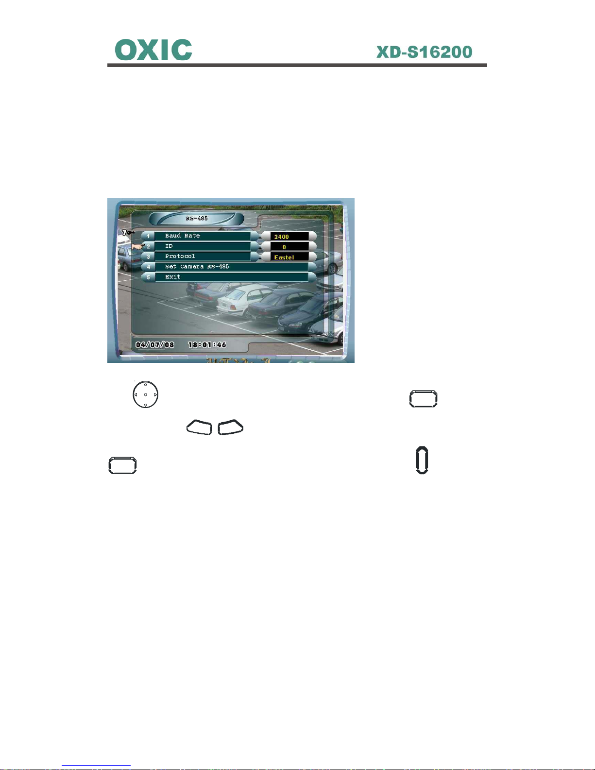
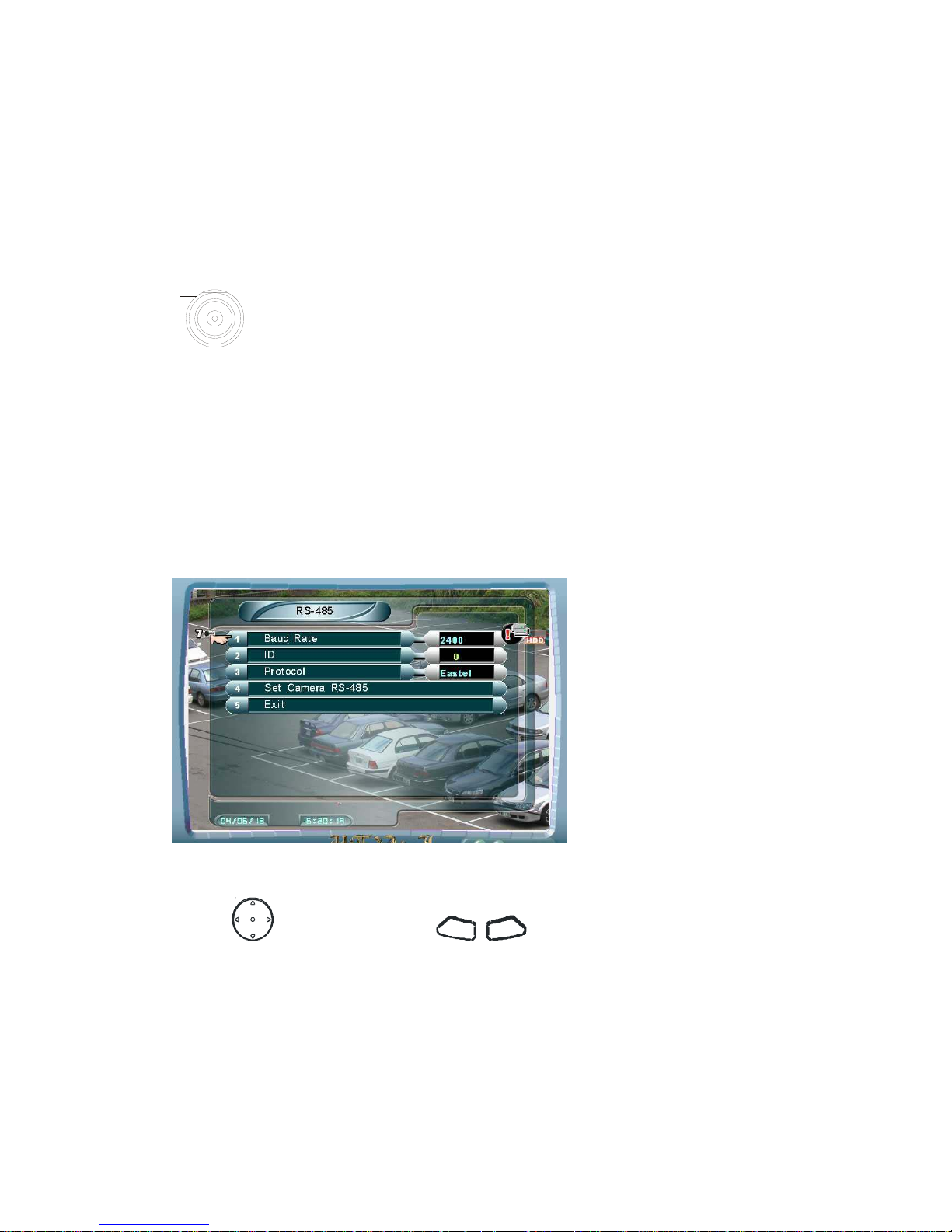
2.6.2 Setup RS-485 in Main Menu to Control Cameras
1. Go to the path: Main Menu Æ Installer Setup Æ RS-485
Figure 2.6.2: RS-485
2. Use
to select item. Use
-
+
to change value.
3. Baud Rate: DVR support 7 kinds of PTZ camera manufacturers protocols,
User needs to refer Dome’s manufacturer manual to set Baud Rate
4. ID: The ID panel here is for DVR’s ID.
5. Protocol: select the brand of the PTZ camera.
1
2
27
27
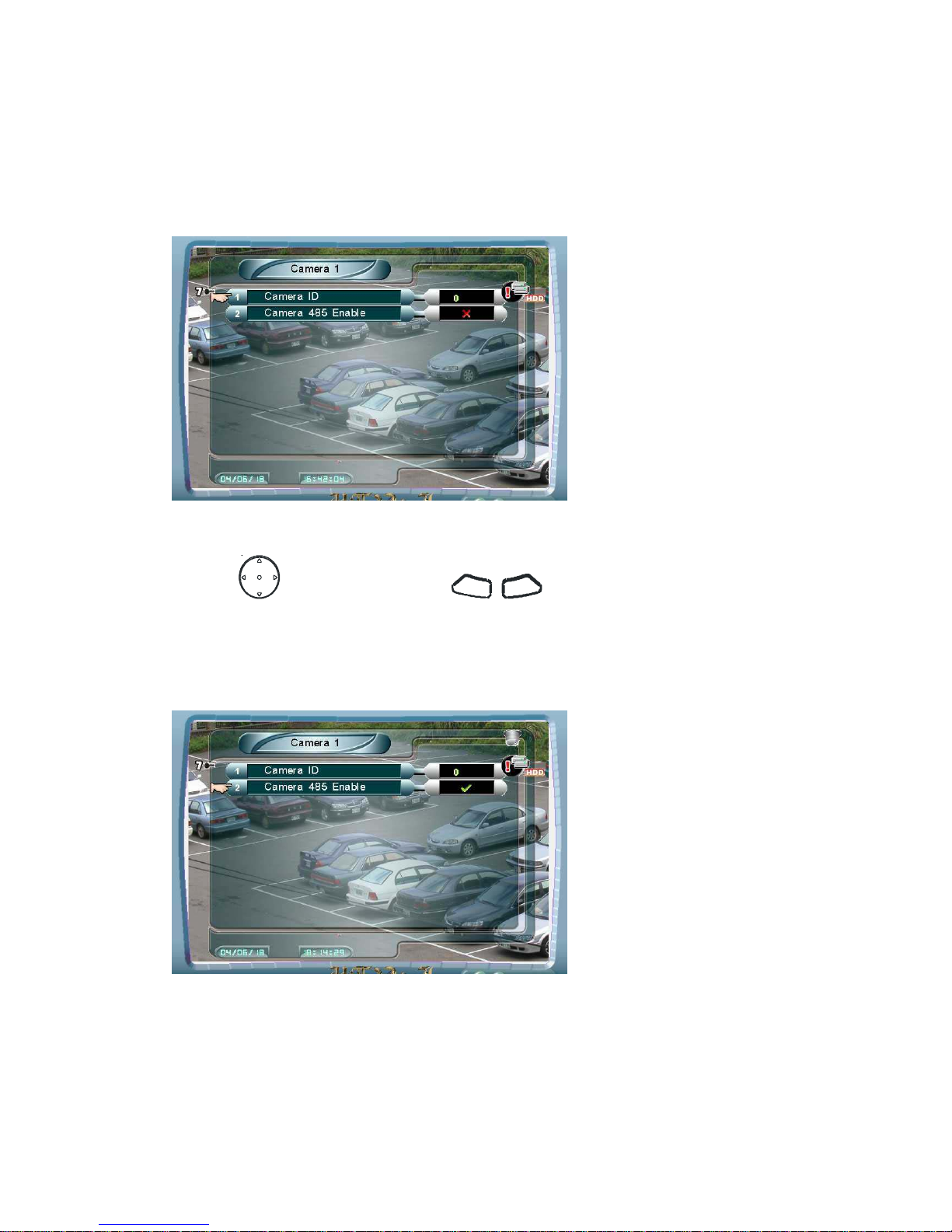
2.6.3 Setup Camera ID & PTZ Camera Enable in DVR Main Menu
1. Go to the path: Main Menu Æ Installer Setup Æ RS-485 Æ Set Camera
RS-485 Æ Camera #
Figure 2.6.3.1: Set camera ID
2. Use to select items. Use
- +
to change values.
3. Set the Camera ID as the same as the switch ID of the dome.
4. Set the Camera 485 Enable enabled for PTZ camera. Dome icon will be
showed on the upper right corner of the screen.
Figure 2.6.3.2: Set Camera 485 Enable
28
28
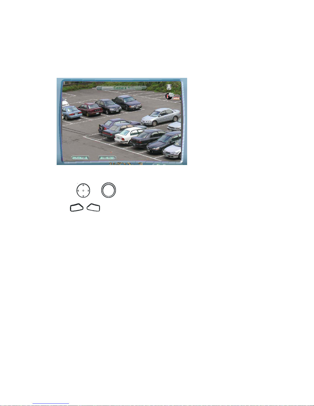
2.6.4 PTZ Camera Control
1. When Camera 485 Enable has been set enabled, there will be a dome label
on the upper right corner in the full screen mode:
Figure 2.6.4: PTZ Camera Control
2. Use or to control PAN left, PAN right, Tilt up, and Tilt down.
Use
+ -
to zoom in/out.
29
29
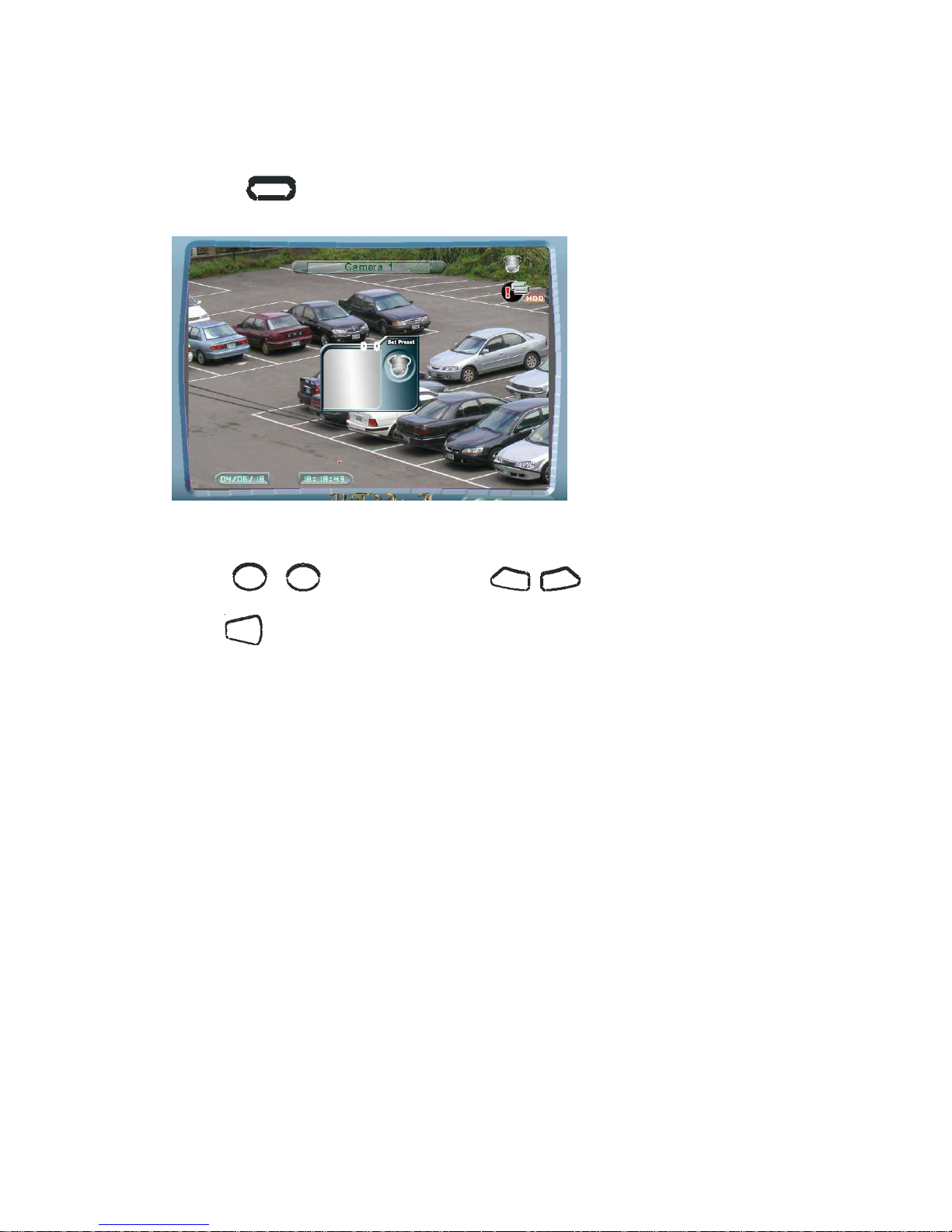
2.6.5 Set Preset for PTZ Camera
1. Press
SET PR ESET
to enter Set Preset mode.
Figure 2.6.5: Set Preset for PTZ Camera
2. Use
1 16
~
to set preset or use
- +
to select preset, then
press
EN TER
to set preset.
NOTE: For Lilin, use the following procedure to set preset point.
Procedure: Recall Goto Preset, set dome at specific location, then Set
Preset.
30
30
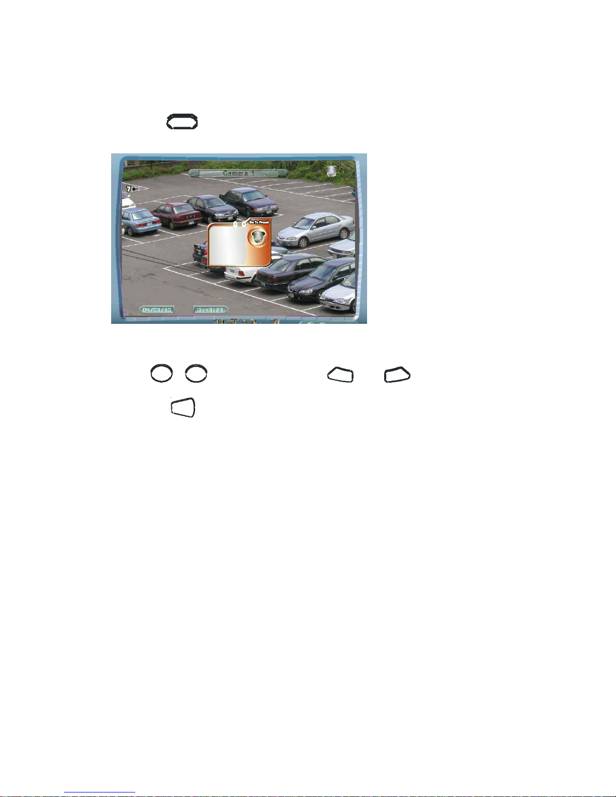
2.6.6 Goto Preset
1. Press
G O TO PR ESET
to enter Go to Preset mode.
Figure 2.6.6: Goto Preset
2. Use
1
16
~
to go to preset or use
-
and
+
to select preset,
then press
EN TER
to go to preset.
 Loading...