

oxic AC24V12VDC Operating Manual

Thank you for choosing this high quality camera, before attempting to
connect or operate this product, please read these instructions completely
DIGITAL COLOR VIDEO CAMERA
ON-SCREEN-DISPLAY
HIGH RESOLUTION
AC24V12VDC Model
AC85 〜 265V
OPERATING MANUAL
z WA RN IN G:
TO REDUCETHE RISK OF FIRE OR ELECTRONIC
SHOCK, DO NOT EXPOSE THIS APPLIANCE TO RAIN OR
MOISTURE AND DO NOT REMOVE COVER OR BACK.
z CAUTION:
1.CONNECT 24VAC UL LISTED CLASS 2 POWER SUPPLY.
2.INSTALL THE CAMERA UNDER UNSTABLE LIGHT SOURCE
MAY CAUSE THE ABNORMAL FUNCTION.
3.ONLY USE CAMERA UNDER CONDITIONS WHERE
TWMPERATURES ARE BETWEEN -10°C to 50°C.
z FIELS INSTALLATION MARKING:
THIS INSTALLATION SHOULD BE MADE BY A QUALIFIED
SERVICE PERSON AND SHOULD CONFORM TO ALL LACAL
CODES
P02-KL-007-C

-2 -
1. General
This a color CCD video camera employs a 1/3 inch charge coupled device
solid-state imaging device with 470/410 k or 310/270k picture elements, This
unit is equipped with a newly developed DSP (Digital Signal Processor) for
processing the video signal. This superior and high sensitive series ensure to
meet any strike 24 hours’ surveillance monitoring demand. A micro-controller is
also introduced to provide high color reproduction, sharp, stable picture and
most of the function’s control; the special feature for this camera is it can
accept IR illumination under minimal lighting condition.
2. Features
z 1/3” SONY Exview HAD / Super HAD with 470 K pixels (410K pixels for NTSC)
z SONY digital signal processor (DSP) allows better picture quality
z Advanced Dual mode resolution form more than 500 TV Lines in color mode to
540 TV Lines in B/W mode
z IR accuracy: Vivid color performance in the day time and sharp B&W image with
no focus shift in the nighttime.
z Smart Optical Low Pass Filter (O.L.P.F) switching mechanism allows changing
between color and monochrome.
z Enhanced O.L.P.F control system (4 modes)
Automatic
Manual
Schedule
External I/O
z Integration GPIO (day/night, IR projector control)
z On Screen Display control (OSD)
z Remote control by RS232C
z Infrared light-sending response wavelength from 700 to 1100 nm
z Intelligent time delay switch
z Friendly back focus mechanical structure to adjust focus distance
z Advanced intelligent circuit design to increase the low light sensitivity 0.1 Lux
color mode down to 0.01 Lux B&W mode (Exview HAD)
z Outstanding signal to noise ratio better than 50 dB
z 255 Areas Auto detects back light compensation
z Internal or
Line-lock external sync
z Isolated switching power DC12V /AC24V , AC85 〜 265 V
.
-3 -
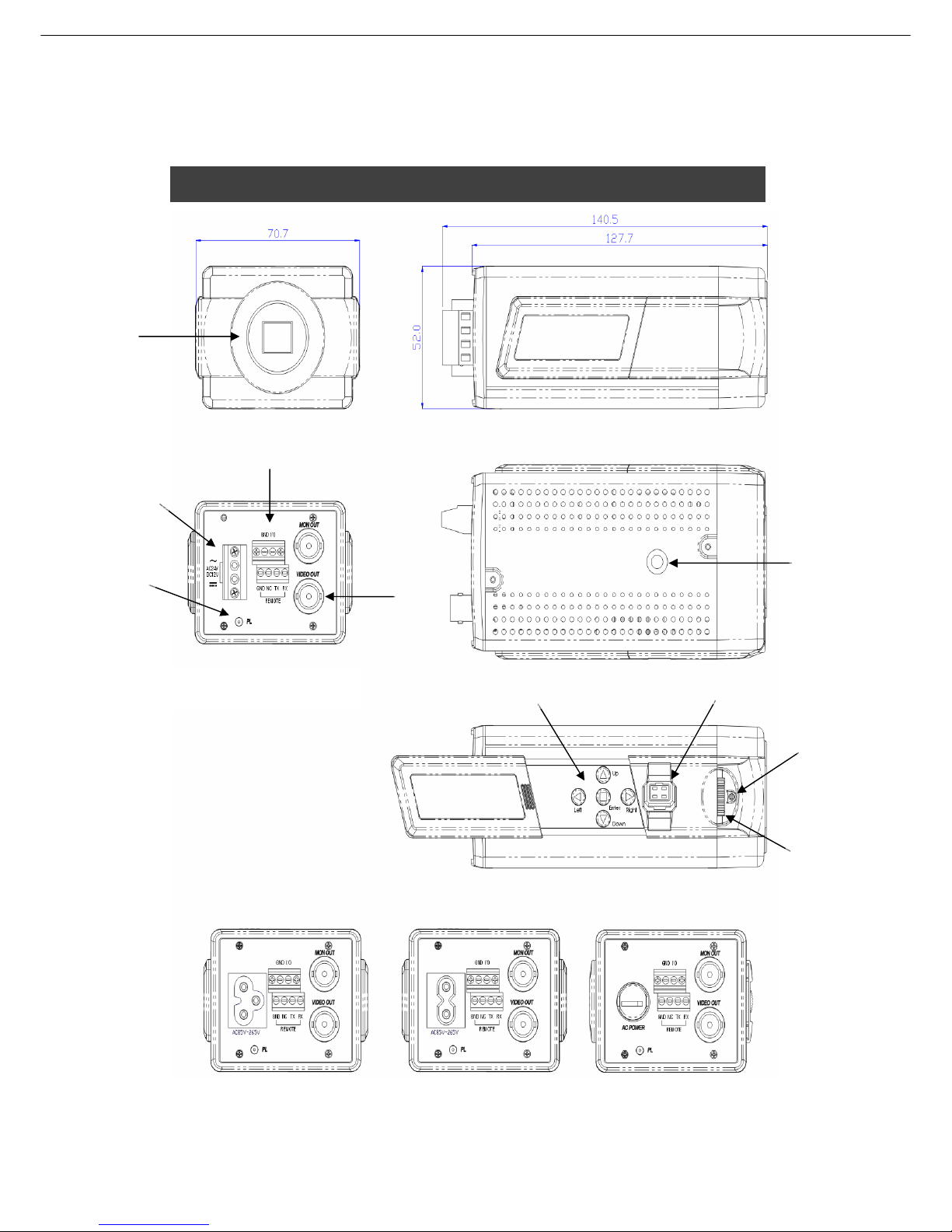
3. Name of Parts and Functions
A
B
C
D
E
F
K
G
I
J
DC12V/AC24 MODEL
AC 85V ~ 265V
3P-PLUG MODEL
AC 85V ~ 265V
2P-PLUG MODEL
AC 85V ~ 265V
AC CORD MODEL
-4 -
A. C (CS) mount adapter if a CS mount lens is to be used, remove the C mount ring
B. Holder screw hole
Standard photographic pan-head screw size (1/4” – 20) Flange focal lock screw
C. Flange focal lock screw
D. Flange focal distance adjuster—if back focus adjustment this ring
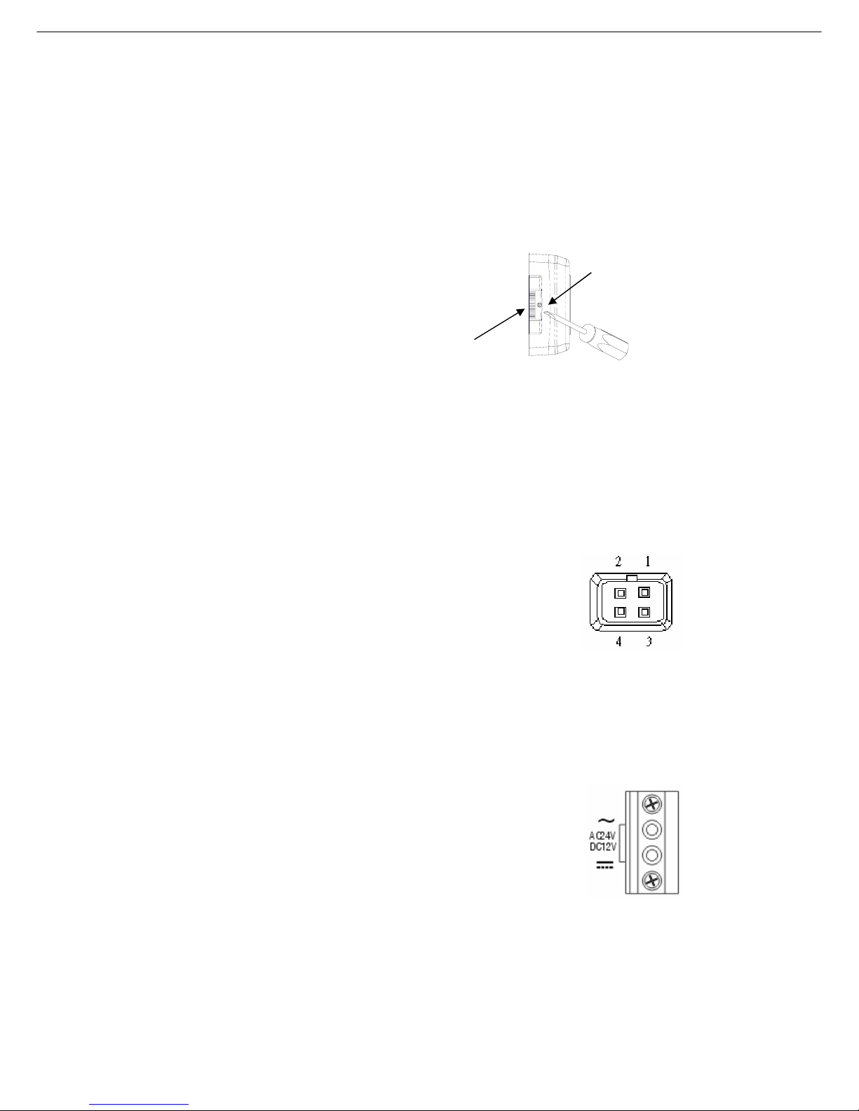
E. Auto iris lens connector (MINI JACK)
Use the accompanying auto iris lens control connector plug.
For auto iris lens is with built-in EE amp. (VIDEO Type)
Set the lens selector switch to ”VD” position.
Connector cable leads
1.Red --- power 3.White --- video
2.NC 4.Black --- shielded
For auto iris lens is without EE amp. (DC Type)
Set the lens selector switch to “DD” position.
Connector cable leads
1. Damping coil (-) 3. Driving coil (+)
2. Damping coil (+) 4. Driving coil (-)
F. Video output terminal (BNC)
This connector is used to connect with the VIDEO IN connector of monitor.
G. On-Screen Display keypad
H. Slide out for control panel
I. Power pilot LED
J. DC12V / AC 24V Block Terminal
This terminal accepts DC 12V(Non-polarity) or AC 24V.
The other model: AC 85 ~ 265V.
K. External project control I/O and Remote control terminal
Back focus
thumbwheel
Thumbwheel locking screw
and provided screwdriver
-5 -
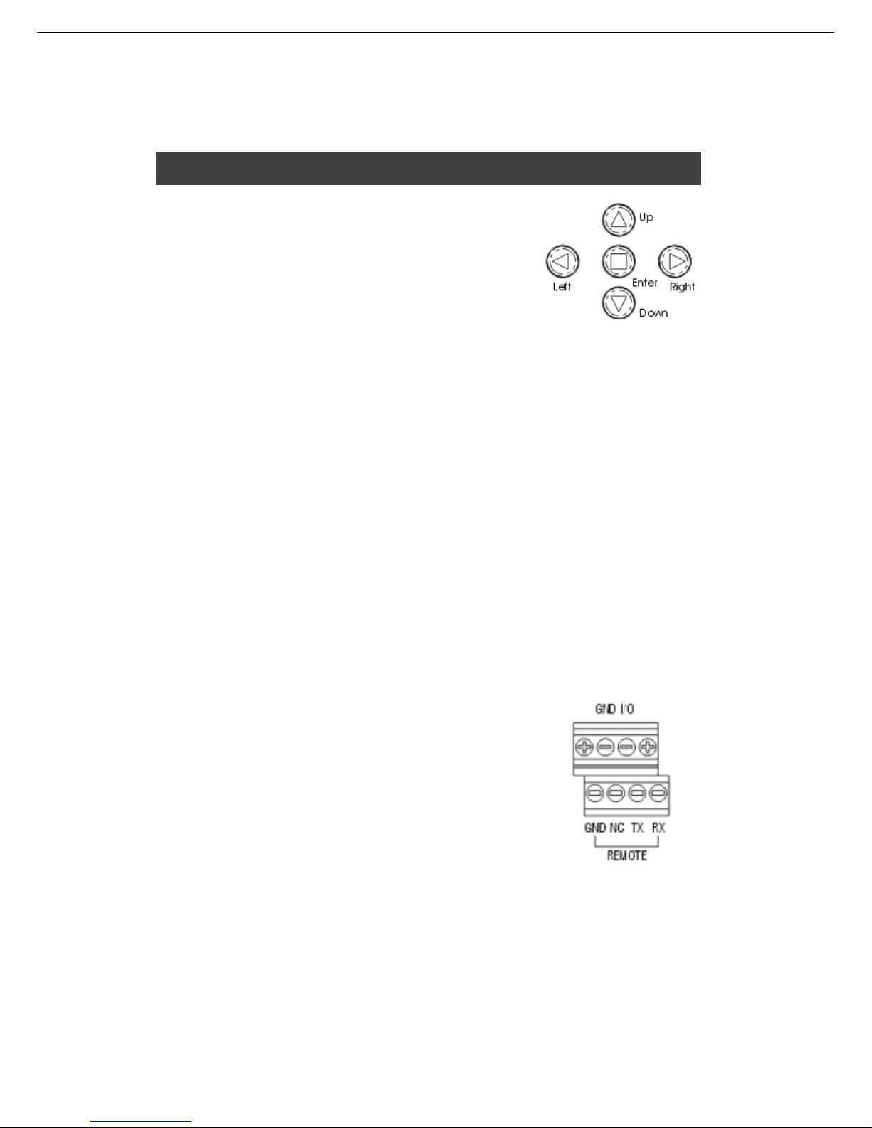
4. USER OSD SETTING
SETTING SWITCHES AND FUNCTIONS
1.UP Button-This button is used to move the cursor
upwards. Use this button to select item.
2.LEFT Button –This button is used to move the cursor
left. Use to select or adjust the parameters of the
selected item.
3.RIGHT button-This button is used to move the cursor to the right. Use to select or
adjust the parameters of the selected item.
4.DOWN Button-This button is used to move the cursor downwards. Use this button
to select item.
5.ENTER Button-Press this button to display the setting menu, if the selected item
has its own menu; press this button to enter sub menu.
PC control
For window 95/98
1. Insert the floppy into diskette, and run OSDV1.exe for auto extract all files into
hard disk
2. Execute Kampro_VK.exe
3. A virtue keypad icon will display on screen
4. Use mouse to point the icons for on-screen-display setting.
RS-232 Connection Please refer to the Setup option
In the program window (com2 default)
1.RX pin----SD (D-sub 9) pin 3 from PC
2.TX pin----RD (D-sub 9) pin 2 from PC
3.NC
4.GND------GND (D-sub9) pin 5
I/O PORT The port can send or receive signal by external device.
Select option mode by OSD D/N function.
The camera can switch day or night by external device when it select external mode.
And other mode can send signal to external device. Day (0V). Night (+5V).
 Loading...