

Oxgard Praktika T-05, Praktika T-05K Installation Manuallines

Praktika T-05(K) speedgate
Installation
guidelines
www.oxgard.com
info@oxgard.com
Tel.+7(812) 366-15-94


Content
1. Basic specifications .................................................................................. 5
2. Product design .......................................................................................... 6
3. Safety requirements .................................................................................. 9
4. Installation of speedgate ......................................................................... 10
4.1. Required equipment ........................................................................ 10
4.2. Installation of speedgate .................................................................. 11
5. Connecting speedgate ............................................................................. 14
5.1. Connecting power supply ................................................................ 15
5.2. Connecting remote control panel .................................................... 16
5.3. Connecting side units ...................................................................... 17
5.4. Connecting access control system (optional).................................. 19
6.1. Card collector description ............................................................... 24
6.2. Connecting power supply ................................................................ 26
6.3. Connecting operating device ........................................................... 27
6.4. Connecting ACS controller ............................................................. 28
6.5. Installation of proximity card reader ............................................... 30
Appendix 1. Summary of the data bus CAN2.0 ........................................ 33
Appendix 2. Block diagram of ACS with using the card reader ............... 35
Appendix 3. Location of mounting holes in relation to the overall
dimensions of the
speedgate…………………………………………………….....38
Appendix 4. Block diagram of minimal connections for synchronized
operation of wings with the use of one RC panel. ..................................... 40
Installation guidelines 3

List of abbreviations
PS – power supply
FA – fire alarm
RC – remote control
ACS – access control system
OD – operating device (turnstile)
NC – normally connected
NO – normally opened
Speedgate firmware version FW v2.0-2.2
Card collector firmware version FW v1.52
Praktika T-05(K) speedgate 4
Dimension of side unit depending on
depending on passage
1. Basic specifications
Table 1 Basic specifications
Description Speedgate RC panel
Dimension of side unit with open wings
(mm) (HхWхL)
passage lane (mm)
660
900
Weight of side unit
lane, kg
660
900
Temperature range, 0C
operation
- transportation and storage
1050х1500х200
1050х1500х500
1050х1500х620
110,0
113,0
+1...+40
+1...+40
107х107х25
107х107х25
0,5
+1...+40
+1...+40
Atmosphere relative humidity, no more
than %
Throughput, persons per minute
Card collector capacity (pcs.)
Max. number of connected RC panels, pcs
Lifetime, years
**
More than 500
80 80
30
2
8 8
Installation guidelines 5
in standby
current operational
1 side
of card
Table 2 Electrical specifications
Description Speedgate Card collector** RC panel
Supply voltage, V:
- nominal
- working
10,8...15,0
12,0
Average current
0,4 0,2
mode * A
Average
3,0
mode * A
Maximal current of
5,0
unit*/***, A
Maximal current
1,5
collector*, A
*- values mentioned at a nominal supply voltage
**-optional
12,0
8…18,0
12,0
7,5...15,0
***- to form a passage area required 2 side units, i.e. 2 power supply 12V 5A
The producer reserves the right to change the packaging, specifications and appearance without
notice
2. Product design
Speedgate housing
Speedgate housing is made of brushed stainless steel, wings are made
of tempered glass. Additionally the card collector can be integrated in the
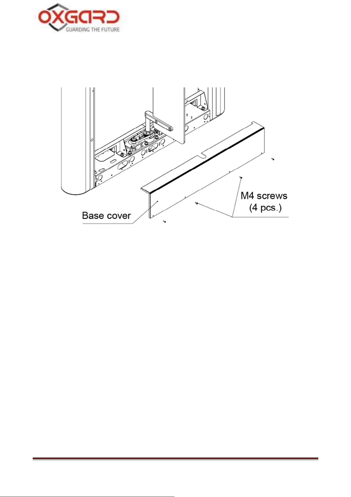
design of the speedgate. Base covers for access to PU, RC and ACS cables
holes (Fig. 1) are provided at the bottom of side units.
Praktika T-05(K) speedgate 6
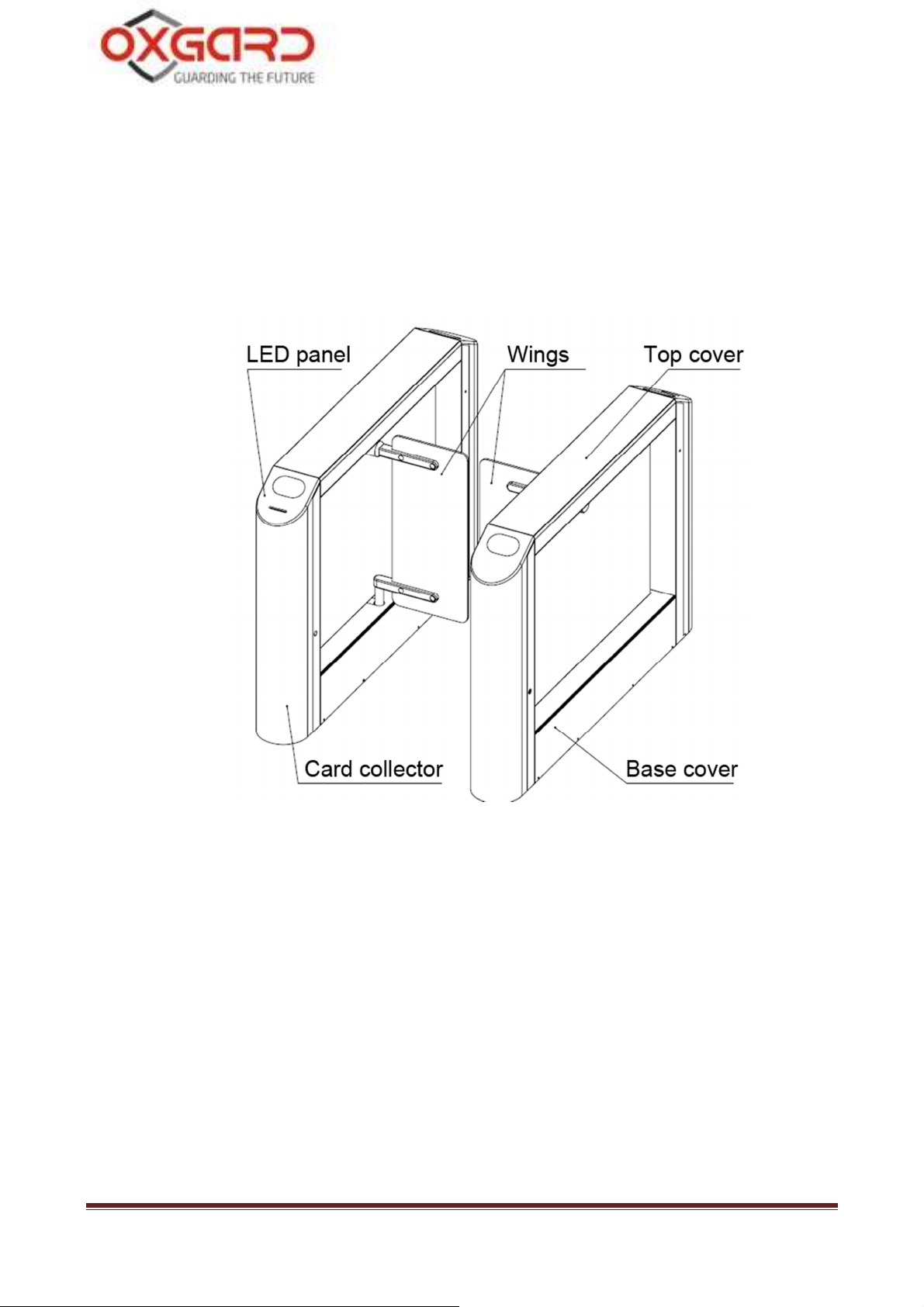
Speedgate may have only a single passage, however an unlimited
number of passages can be arranged with the use of side units and middle
units, depending on customer requirements.
Fig. 1 General view of speedgate
LED panel
Display panel of the speedgate is made of artificial stone with an
insertion made of acrylic glass. Speedgate operating modes are displayed
on the panel in the form of mnemonic signs depicting authorization and
non-authorization (Fig. 2).
Installation guidelines 7
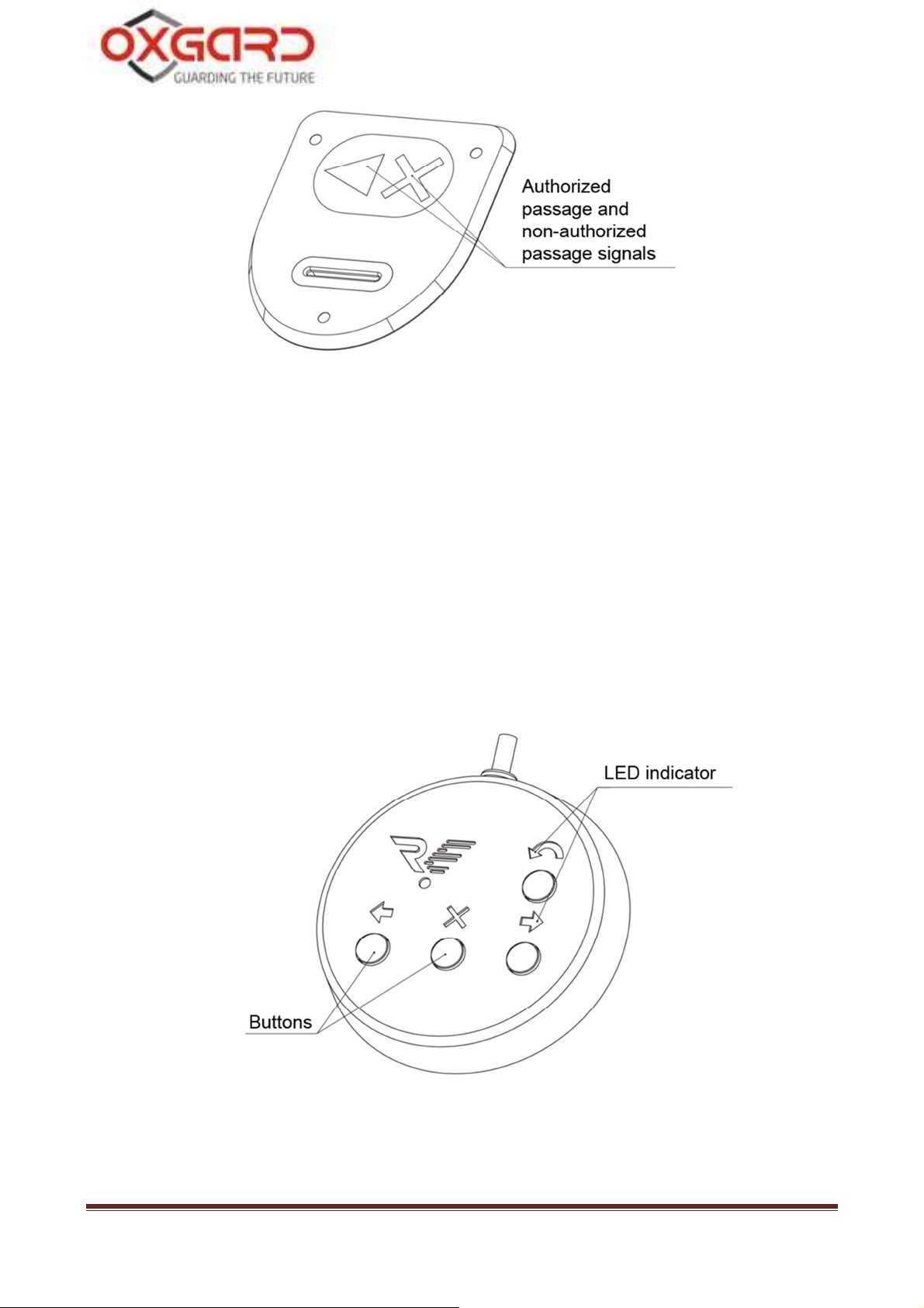
Fig. 2 General view of LED panel display
Remote Control Panel
The housing of RC panel is made of polished stainless steel. On the
front side there are control buttons and LED indicators of RC operational
modes (Fig. 3). The standard supplied cable is 5 m long.
Fig. 3 General view of remote control panel
Praktika T-05(K) speedgate 8
3. Safety requirements
CAUTION! Failure to comply with the safety requirements specified in
this section may result in damage to human life and health, total or partial
loss of workability of products and (or) auxiliary equipment.
CAUTION! The producer disclaims any liability for damage to human life
and health, total or partial loss of workability of products and (or) auxiliary
equipment for non-compliance of the safety requirements specified in this
section, as well as terminates the product warranty.
IT IS NOT ALLOWED TO:
• Set the power supply unit inside the speedgate housing as this could
lead to electric shock to persons;
• Set the speedgate other than in dry and heated places;
• Impede or accelerate the speedgate wings;
• Apply chemically aggressive cleaning detergents as pastes and
liquids.
Installation guidelines 9
4. Installation of speedgate
CAUTION: The speedgate should be installed securely to avoid swinging
and (or) overthrow during operation. In case of installation on the low
strength floors - take action to strengthen the floor at the installation site.
Before checking operability of the speedgate carefully read this section of
the Regulations.
4.1. Required equipment
Tools used for card reader mounting:
• Electric perforator;
• 20mm diameter carbide drill for drilling holes in the floor for anchors
(recommended anchor - SORMAT PFG LB 12-50);
• wrench for hexagon socket head screws S10;
• slotted screwdriver;
• plumb line or level;
• steel underlayer for turnstile alignment
• round file
• side cutters
Praktika T-05(K) speedgate 10
mark the mounting holes corresponding to
ness of installation
take into account
4.2. Installation of speedgate
CAUTION! We recommend to
side unit base holes when the wings are already installed.
CAUTION! During installation take into account that glass wings cannot
be adjusted. It is recommended to check the correct
before fixing the side units.
CAUTION! During preparation of the installation site
that each side unit requires a separate power supply.
CAUTION! During installation of the speedgate prepare conduits for cable
routing of CAN-bus to connect side units
4.2.1. Prepare horizontal surface at the installation site of
speedgate.
4.2.2. Prepare conduits or cable channels from the site to the
installation site of PU, RC, as well as, if required, to the point of ACS
connection and FA.
4.2.3. Follow the layout and drill 12 holes of 20mm diameter for
floor anchors. Location of mounting holes related to the outer
dimensions of the speedgate and its dimensions are shown in Appendix
4. Depth of the hole should exceed the length of the anchor more than
5mm. Put anchors into holes.
Installation guidelines 11
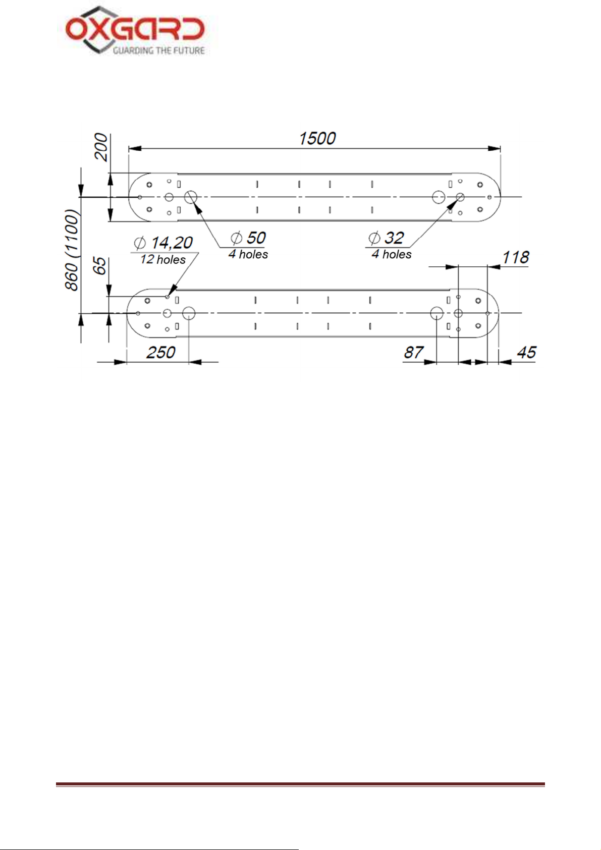
4.2.4. Cable routing is carried out through holes of 50 mm
diameter (Fig. 4) in the lower plate of side units.
Fig. 4. Linkage dimension with 660 (900) mm passage width
4.2.5. Open the box and unpack:
• side units;
• remote control panel with cable;
• lock keys (8 pcs.).
4.2.6. Route cable of RC panel, cable of PS unit, cable of
CAN-Bus, and, if provided, cables of FA and ACS into cable channel or
conduit.
4.2.7. Set the side units of speedgate on a prepared site. Unscrew
the 4 units of M4 screws and remove the base cover (Fig. 5).
Praktika T-05(K) speedgate 12
4.2.8. Put housing cables of RC, PS, CAN-bus and, if necessary,
cables of FA and ACS inside speedgate housing. Secure cables with
cable ties.
Fig. 5 Installation diagram of side unit
4.2.9. Align together the holes in the lower plate of side unit and
anchors in the floor. Check the vertical installation in 2 planes. If
necessary, use appropriate steel underlayers for proper installation of the
speedgate. Fix the housing of side unit with 12 screws M10, tightening
them to the corresponding anchors by using a wrench with internal
hexagon S10.
4.2.10. Remove protective film from the housing of the speedgate.
Installation guidelines 13
5. Connecting speedgate
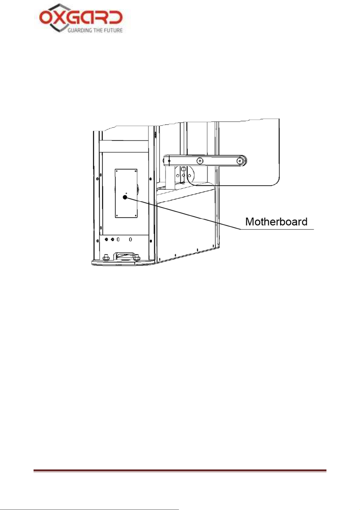
Connection of RC, PS and ACS is performed with the use of
motherboard. Figure 6 shows the location of motherboard at the front of
the side unit.
Figure 7 depicts the motherboard and connectors for PS, RC, ACS
and FA.
Fig. 6 Location of motherboard on the side unit
Praktika T-05(K) speedgate 14
 Loading...