

Page 1

VOZROZHDENIE, LLC
OKPD 2 26.30.50.110
TU 26.30.50-007-33120038-2017
APPROVED
VZR.235900.000 VZR.235900.000 LU
TURNSTILE
MODEL CUBE С-04
С-04-c, С-04-К, С-04-Кc, С-04-H, С-04-Hc, С-04-НК, С-04-НКc
VZR.235900.000 OM
OPERATIONAL MANUAL
Sheets 48
2019
Page 2

VZR.235900.000 OM
Turnstile Cube С-04
Operational Manual
CONTENTS
1. Description and Operation ............................................................................................................. 4
1.1 Description and operation of the Product ................................................................................ 4
1.3 Card collector description and operation (optionally) ............................................................ 11
2 Intended Use ................................................................................................................................. 12
2.1 Operating Limitations ............................................................................................................ 12
2.2 Preparing the product for use ............................................................................................... 13
2.3 Product Operation ................................................................................................................ 17
2.4 Procedure for actions in extreme situations .......................................................................... 26
2.5 Product Calibration ............................................................................................................... 27
3 Maintenance .................................................................................................................................. 28
3.1 General Guidelines ............................................................................................................... 28
3.2 Safety Precautions ............................................................................................................... 29
3.3 Product maintenance procedure ........................................................................................... 30
3.4 Product external examination ............................................................................................... 30
3.5 Product partial disassembly .................................................................................................. 31
3.6 Inspection of product assemblies.......................................................................................... 33
3.7 Lubrication of product mechanism moving parts ................................................................... 34
3.8 Product assembly and serviceability check ........................................................................... 34
4 Current Repair ............................................................................................................................... 36
4.1 Product current repair ........................................................................................................... 36
4.2 Current repair of product component parts ........................................................................... 37
4.3 Faults during warranty period ............................................................................................... 37
5 Storage .......................................................................................................................................... 38
6 Transportation ............................................................................................................................... 39
7 Disposal ......................................................................................................................................... 40
APP E NDI X A — Distributors and service centers ............................................................................. 41
List of approved abbreviations ........................................................................................................... 47
2
Page 3

VZR.235900.000 OM
Turnstile Cube С-04
Operational Manual
This Operational Manual (OM) applies to Turnstile Oxgard Cube С-04 and
its modifications (hereinafter referred to as “the product”). The firmware version of
the product: FW v2.2
The manufacturer reserves the right to change the product’s scope of
supply, technical data and appearance without any additional notices.
Prior to operating the product, the personnel should additionally become
familiar with Datasheet VZR.235900.000 DS.
This OM is the document certifying basic parameters and performance of
the product, which are guaranteed by the manufacturer.
OM is designed to instruct on the product’s principle of operation, its
structure and design in order to ensure its proper operation, full use of its technical
capabilities and to keep it constantly ready for operation.
3
Page 4

VZR.235900.000 OM
Turnstile Cube С-04
Operational Manual
1. DESCRIPTION AND OPERATION
1.1 Description and operation of the Product
Turnstile Oxgard Cube С-04 is designed to control access and
manage people’s streams by dividing their stream in a “one-by-one” manner.
The product can be used at checkpoints of enterprises, organiz ations and
banks, educational institutions, sports and entertainment centers, stores, stations
and other facilities. To provide easy and fast passage of people, it is
recommended to install one product for every 500 people working on a one-shift
basis.
The product’s scope of supply is detailed in Table 1.
Table 1 – Product’s scope of supply
Designation Description Quantity Note
Turnstile Cube С-04 1
RC panel Praktika multi-purpose control panel 1
Power supply unit* 1
Reader for PC* 1
Card collector* 1
Barrier section set* Praktika barrier 1
Note — The product’s component parts marked with (*) are supplied optionally.
4
Page 5

VZR.235900.000 OM
Turnstile Cube С-04
Operational Manual
1) two readers are built in housing with LED highlighting;
the turnstile is equipped with simple card withdrawal access
the turnstile is equipped with simple card withdrawal access
The individual features of the product modifications.
The turnstile housing can be designed in two options:
Option No.1: side covers and central overlays are made of stainless steel,
and the internal stand elements and the top cover are painted (color according tor
the Customer's choice).
Table 2 – Complete set of turnstile modifi ca tions.
Table 2 – Turnstile modifications (Option No.1)
Modification Features
С-04-Кс (Card collector +
Reader)
С-04-К (Card collector)
С-04-с (Reader)
С-04
2) built-in card collector, containing 200 visitor cards;
3)
system;
4) the housing includes the painted elements.
1) the built-in card collector, containing 200 visitor cards;
2)
system;
3) the housing includes painted elements.
1) two readers are built in housing with LED illumination;
2) the housing includes the painted elements.
1) the housing includes the painted elements.
2) without readers.
5
Page 6

VZR.235900.000 OM
Turnstile Cube С-04
Operational Manual
1) two readers are built in the housing with LED illumination;
the turnstile is equipped with simple card withdrawal access
1) built-in card collector, containing 200 visitor cards;
the turnstile is equipped with simple card withdrawal access
Option No.2: all overlay turnstile elements shall be made of stainless steel.
Table 3 – Complete set of turnstile modifications.
Table 3 – Turnstile modifications (Option No.2)
Modification Features
2) built-in card collector, containing 200 visitor c ards;
С-04-НКс (Card colle c tor +
Reader)
3)
system;
4) stainless steel housing.
С-04-НК (Card collector)
С-04-Нс (Reader)
С-04-Н
2)
system;
3) stainless steel housing.
1) two readers are built in housing with LED illumination;
2) stainless steel overlays.
1) stainless steel housing.
2) without readers.
Barrier arms of all the tur nstile modifications are made of ground stainless
steel.
In the product modifications with readers – the readers of magnetic cards
PROX-13 or PROX-125 are installed (specified in the turnstile order). The readers
are installed on the turnstile left and right side into the stand top parts.
6
Page 7

VZR.235900.000 OM
Turnstile Cube С-04
Operational Manual
Overall dimensions (HхWхL), mm:
Temperature range, °С:
Power supply voltage (direct current), V:
- operating
10.8...13.2
The product Specifications are given in Table 4
Table 4 - Specifications
Parameter description Value
- in operating condition
- with assembled arms
Weight, kg 50.0
- operation
- transportation and storage
Relative air humidity, %, maximum 80
Width of formed passage, mm 565-595
Through-flow rate, pax per min 30
Max number of connected RC panels, pcs. 2
Service life, years 8
1000х950х735
1000х950х192
+1...+40
+1...+40
- nominal
Average current in suspended mode*, A 1.5
Average current in passage mode*, A 1.5
Maximum consumption current*, A 3.0
12.0
Note — * the values of current are specified under nominal power supply voltage
7
Page 8
VZR.235900.000 OM
Turnstile Cube С-04
Operational Manual
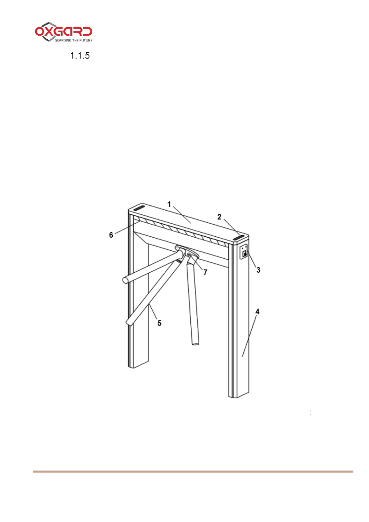
1 - top cover; 2 – card collector slot; 3 – reader;
Product design.
The side covers, central overlays and products a re made of stainl ess st eel,
and the internal stand elements and the top cover are painted (color according tor
the Customer's choice). The turnstile’s barrier arms are made of ground stainless
steel. Housing fitted with LED illumination.
For connection of PSU, RC panel and AMCS cables, the motherboard,
located and removable cover in the product housing top part is used. A hole is
provided in the bottom part of the product housing to input these cables.
Figure 1 – General view of the product
4 – side decorative covers; 5 –barrier arms;
6 – front display model; 7 - arms fixation locking device
Figure 1 – Turnstile’s general view
8
Page 9
VZR.235900.000 OM
Turnstile Cube С-04
Operational Manual
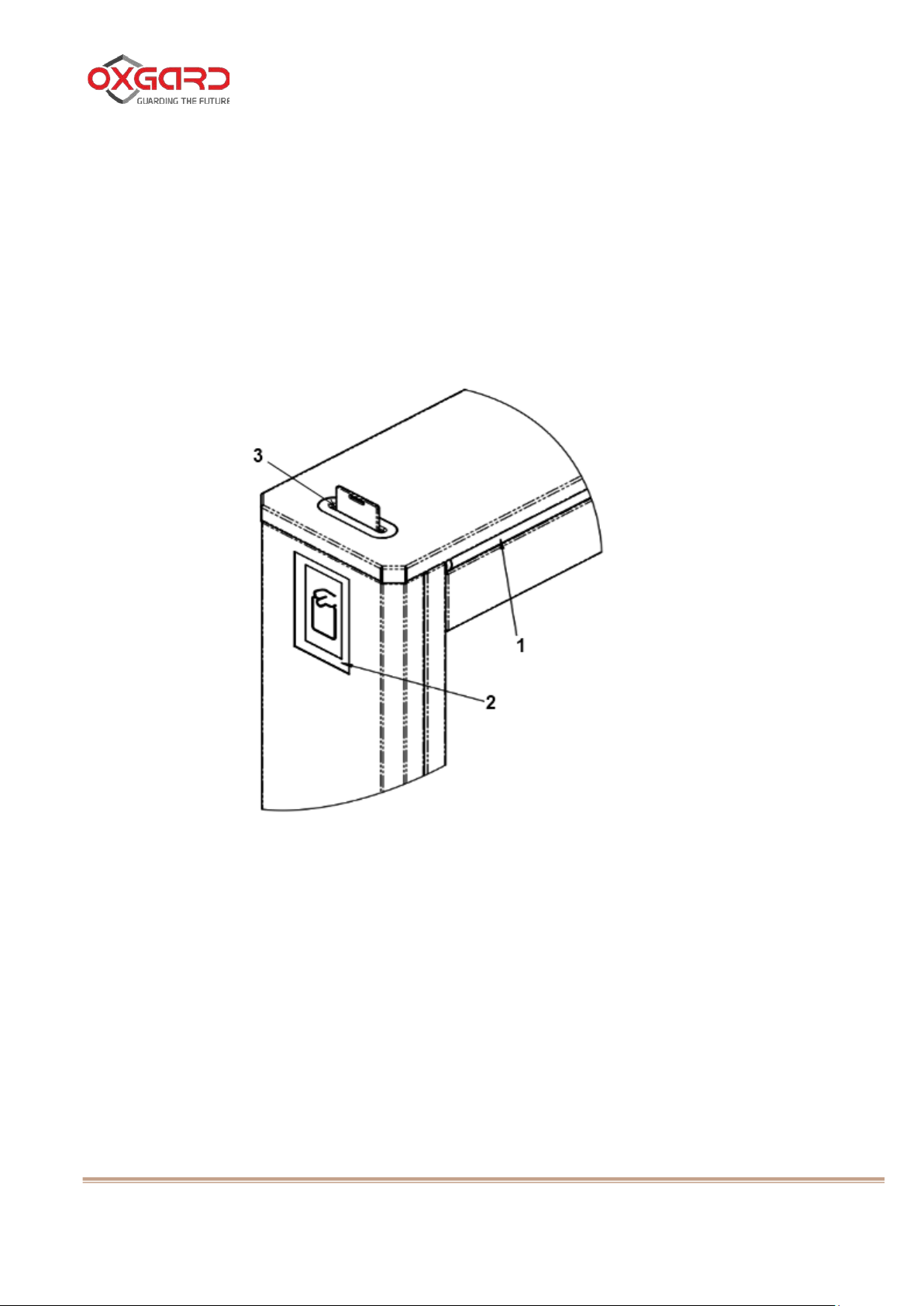
1 - front display model;
1.1.6 Display system.
The turnstile front display panel is located in the turnstile top part with the
Caprolon insert.
Figure 2 - Turnstile modes of operation are displayed on the front display
panel (1) and are duplicated with the side display panels (2).
1.1.7 The labeling includes the manufacturer's trademark, designation, serial number.
1.1.8 Overall dimensions of the packaging containers make:
1) Height - 1170 mm;
2) Width - 500 mm;
3) Length - 1040 mm.
2 - side display panel;
3 - card collector slot
Figure 2 - Display system appearance
9
Page 10

VZR.235900.000 OM
Turnstile Cube С-04
Operational Manual
Temperature range, °С:
Power supply voltage (direct current), V:
- operating
7.5...15.0
1.2 Desc ription and Operation of Oxgard Praktika RC Panel
Multi-purpose Oxgard Praktika console is designed for control of Oxgard
turnstiles.
1.2.1 The housing is made of stainless steel; the control buttons and the LED operation mode indicators are located on the front side. Specifications are given in Table 5.
Table 5 - Specifications
Parameter description Value
Overall dimensions (HхWхL), mm: 25х107х107
Weight, kg 0.5
- operation
- transportation and storage
Relative air humidity, %, maximum 80
Service life, years 8
- nominal
+1...+40
+1...+40
12.0
1.2.2 Design features:
1) An option for connection of two consoles to one turnstile;
2) High interference resistance;
3) The wire length from console turnstile can make up to several kilometers with no
loss of command transmission rate;
4) Standard length of the cable supplied in the complete set makes 5 metres.
10
Page 11

VZR.235900.000 OM
Turnstile Cube С-04
Operational Manual
1.3 Card collector descri pti on a nd operation (optionall y)
1.3.1 Card collector purpose
The card collector is designed for collection and storage of swipe cards
upon leaving the facility. Flexible card collector controller operation logic and
connection allows for its integration with any access monitoring and control
systems.
1.3.2 Description of construction elements. Figure 2 - Card collector slot.
On the inner side of card collector stands there are two containers with
locks for fast access to withdrawn cards.
The container design allows for containing at least 200 cards.
Note — The Customer selects the side of the card collector installation on the product,
which is stipulated during supply agreement conclusion
11
Page 12

VZR.235900.000 OM
Turnstile Cube С-04
Operational Manual
2. INTENDED USE
2.1 Opera ti ng Limitations
ATTENTION: FAILURE TO COMPLY WITH SAFETY
REQUIREMENTS SPECIFIED IN THIS SECTION MAY CAUSE DAMAGE TO
HUMAN LIFE AND HEALTH, AND FULL OR PARTIAL LOSS OF THE
OPERABILITY OF THE PRODUCT AND/OR A UX ILIARY EQUIPMENT.
ATTENTION: THE TURNSTILE INSTALLATION SHALL BE
CARRIED OUT BY QUALIFIED SPECIALISTS IN ACCORDANCE WITH
INSTALLATION GUIDELINES.
ATTENTION: IN CASE OF FAILURE TO COMPLY WITH SAFETY
REQUIREMENTS SPECIFIED IN THIS SECTION, THE MANUFACTURER
SHALL NOT BE HELD LIABLE FOR DAMAGE TO HUMAN LIFE AND HEALTH,
FULL OR PARTIAL LOSS OF THE OPERABILITY OF THE PRODUCT AND/OR
AUXILIARY EQUIPMENT, AND TERMINATE THE PRODUCT’S WARRANTY.
12
Page 13

VZR.235900.000 OM
Turnstile Cube С-04
Operational Manual
IT IS NOT ALLOWED:
INSTALL THE POWER S UP P L Y UNI T INSIDE THE TURNSTILE CA S ING,
BECAUSE THIS MAY CAUSE ELECTROCUTIO N.
INSTALL THE TURNSTILE ANYWHERE OUTSIDE DRY AND HEATED
ROOMS.
OBSTRUCT OR ACCELERATE THE MOVEMENT OF THE TURNSTILE
BARS.
USE FOR CLEANING ANY PASTES OR FLUIDS THAT ARE
CHEMICALLY AGGRESSIVE TO MATERIALS OF THE HOUSING.
2.2 Preparing the product for use
2.2.1 Safety precautions during the preparation of the product for use
ATTENTION: PRIOR TO TURNSTILE CONNECTION, FREE THE
ARMS RO TATION ZONE FROM PEOPLE AND FO REIGN OBLECTS TO AVOID
INJURIES AND TURNSTILE LOCKI NG.
2.2.2 Regulations and procedure for product inspection
The product visual inspection prior to its connection to power supply
network is mandatory and includes:
1) checkup for no mechanical damage of the product housing: checkup for no cracks,
through holes from lost fasteners;
2) careful inspection of all product connections.
13
Page 14

VZR.235900.000 OM
Turnstile Cube С-04
Operational Manual
2.2.3 Product switching on.
The turnstile arrives to the Customer in the assembled state (transportation
mode).
Prior to starting operation, it shall be switched to working position: pull off
the arm fixation locking device (Figure – 7) holdin g one arm with hand in the fixed
position, distribute the rest of the arms in the operating position.
Connect PSU to ~220 Volt mains and and then switch it on. Red indication
will light on the turnstile front display panel.
The side display panels will illuminate red. The passage will then be closed,
the LED button indicator (Figure 5 - 2) w ill illuminate red on the RC panel.
One of the arms will be in the blocking condition, which prohibits the
passage.
The turnstile is ready for operation.
14
Page 15
VZR.235900.000 OM
Turnstile Cube С-04
Operational Manual
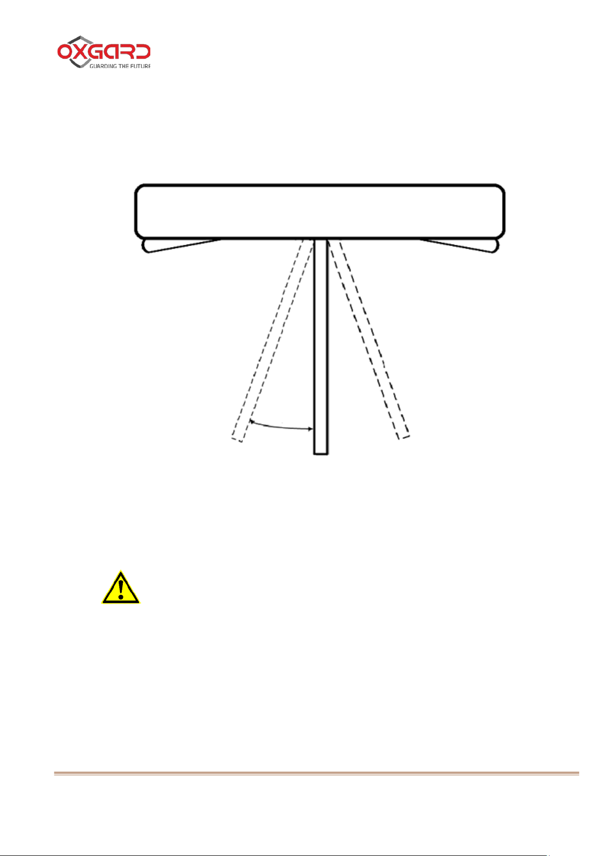
6 deg
2.2.4 Inspection and checkout of product readiness for use:
Figure 3 - possible free travel of the arm. In “STOP” mode, it makes 6
degrees on each side.
Figure 3 - Possible free travel of the arm in “STOP” mode
2.2.5 Guidelines on product orientation.
ATTENTION: PASSAGE ZONES SHALL BE PROVIDED TO
ALLOW RECORDING OF PASSAGES DURING TURNSTILE OPERATION
UNDER AMCS CONTROL AND TO AVOID UNAUTHO RIZED P A S S A GES .
15
Page 16

VZR.235900.000 OM
Turnstile Cube С-04
Operational Manual
Recommended diagram
Non-recommended diagram
200 mm min
50 mm max
1 - barrier
Figure 4 - Turnstile passage zone arrangement.
2.2.6 Control console settings
Figure 5 – Appearance of RC panel. In relation to the user, the product can
be installed using different methods. In some cases, it is required to change
positions of left/right passage buttons. This may be done by means of the
following operations:
Switch off the product power supply;
3) Push and hold left (1) and right (3) buttons;
4) Switch on the product power supply;
5) Holding buttons 1 and 3, push stop button (2);
6) Release buttons 1 and 3;
7) Release button 2.
Now, upon pushing “left” button, the right passage will be authorized, and
vice versa. Current dedication of buttons is stored in the memory and is not reset
16
Page 17

VZR.235900.000 OM
Turnstile Cube С-04
Operational Manual
1 - left; 2 - stop; 3 - right; 4 - antipanic
upon power supply disconnection. For return to original option, it is necessary to
perform the above mentioned sequence of operations again.
Figure 5 - control buttons 1 (left), 2 (stop), 3 (right), 4 (antipanic) and the
product operation mode LED indicators.
Figure 5 – Appearance of RC panel
2.3 Product Operation
2.3.1 Product operating modes
The product has several operating modes. Switch to the desired mode
using RC panel or AMCS. Indication of operating modes is displayed on the panel
in the form of passage authorization and prohibition mnemonic symbols.
Operation of the product with AMCS is considered in IG.
17
Page 18

VZR.235900.000 OM
Turnstile Cube С-04
Operational Manual
2.3.2 Product operation by means of RC panel
Figure 5 - The LED indicator displaying the turnstile operating mode is
located above each RC panel’s button.
“Stop” Mode
The “Stop” mode is set during switching on the product. Switc hi ng to “ Stop”
mode from the other mode is performed using button 2. At that, the LED indicator
above RC panel’s button 2 illuminates red. At that, the front and side display
panels glow red. In this mode, both ways passage is prohibited.
The middle arm may be deviated from the initial position by a small angle of
6 degrees. Upon arm deviation, the locking device will actuate automatically and
will not let the arm turn for passage execution.
Single passage mode
Button 1(3) actuates the left (r ight) single passage mode. Upon this mode
actuation, the single left (right) passage with subsequent switching to “Stop” mode
will be authorized.
At that, the side display panel glows green, demonstrating free left (right)
passage. On the front display panel, the group of red lights is running in the
authorized passage direction.
On RC panel, the LED indicator illuminates green above the button, to
which the passage is authorized, and it illuminates red above button 2. If the
passage was not performed during 5 seconds, the product switches to “Stop”
mode automatically.
Multi-passage mode in one direction
18
Page 19

VZR.235900.000 OM
Turnstile Cube С-04
Operational Manual
Push and hold button 2 for switching to this mode; push button 1(3) after
that. After that, both buttons may be released.
The multi-passage mode is displayed on RC panel by green indication
above button 1(3), the red LED indicator above button 2 does not glow.
The side display panel glows green demonstrating free left (right) passage;
on the front display panel, the group of red lights is running in the authorized
passage direction.
In this mode, the passage in the authorized direction may be performed for
unlimited times.
There is also an option to authorize a single passage in the prohibited
direction pushing button 1(3). After this passage performance or upon expiry of 5
seconds, the product will return to the initial mode.
Free passage mode
For switching to this mode, push and hold button 1, after which push
button 3 and release both buttons. In this mode, the both way passages for
unlimited times are allowed.
The side display panels glow green demonstrating free left (right) passage;
on the front display panel, two divergent groups of red lights are moving.
On RC panel, the LED indicators above buttons 1 and 3 illuminate green.
19
Page 20

VZR.235900.000 OM
Turnstile Cube С-04
Operational Manual
1 - arm fixation locking device
“Antipanic” Mode
Switching to this mode is carried out mechanically.
Put the turnstile to “Antipanic” mode; for this purpose, push button 4 on RC
panel.
Pull off the arm fixation locking device (Figure – 7) holding one arm with
hand in the fixed position, turn over the second arm clockwise with the other hand
so that all bars match each other (Figure 7 - 1).
Figure 6 - Bar fixation locking device
20
Page 21

VZR.235900.000 OM
Turnstile Cube С-04
Operational Manual
Figure 7 - Then, screw down all assembled arms.
The side display panels glow green demonstrating free left (right) passage;
on the front display panel, two divergent groups of red lights are moving with
increased speed.
Figure 7 - Turnstile view with assembled bars
21
Page 22

VZR.235900.000 OM
Turnstile Cube С-04
Operational Manual
2.3.3 Product operation by means of card collector
Upon power up, the suspended mode is set. Switching to the other mode is
carried out upon swipe card presentation.
Passage by Permanent Visitor Card
Upon authorized permanent visitor card presentation (it is just enough to
hold the card to readout device). the card collector will unlock the turnstile for a
time set up by AMCS controller (it depends on operation mode; for 5 seconds - in
pulse mode). During the set time interval the other cards are not accepted.
In case of passage performance or the set time interval expiry. the card
collector switches to suspended mode and may accept the next card.
At that, the side display panel glows green and demonstrates free left
(right) passage. On the front display panel, the group of red lights is running in the
authorized passage direction.
Passage by Visitor Card
The visitor card shall be inserted into the slot until stop, otherwise, it will be
ignored. in case of the authorized card presentation, the card collector withdraws
it, after which the card collector unlocks the turnstile for 5 seconds.
Emergency Mode
In the course of card collector operation, different unforeseen situations
may occur, during which the card or the foreign object are clamped by the card
collector door. The emergency mode is designed for elimination of similar
situations.
22
Page 23

VZR.235900.000 OM
Turnstile Cube С-04
Operational Manual
1 - card collector container;
For this purpose, it is necessary to remove the turnstile and get access to
the card collector board.
Figure 8 - Open it with the key and remove both containers located inside
the turnstile stands.
2 - side cover; 3 - top cover
Figure 8 - Card collector container
23
Page 24

VZR.235900.000 OM
Turnstile Cube С-04
Operational Manual
1 - cover mounting studs
Figure 9 - Release 4 top cover mounting studs and remove the cover in the
specified direction.
Figure 9 - Top cover dismounting
24
Page 25

VZR.235900.000 OM
Turnstile Cube С-04
Operational Manual
Figure 10 - Push and hold button BUT1 on the card collector board. With
the pushed button, the card collector door is forcibly opened and continuous
sound signal sounds.
Extract the object preventing system normal operation.
Figure 10 - Release button BUT1.
Figure 10 - Card collector Board Appearance
Install the top cover and the containers back.
2.3.4 Extraction of visitor cards out of card collector container
Figure 8 – Open the container lock using the key. Remove the container
and collect the visitor cards.
Then install the container in-place.
25
Page 26

VZR.235900.000 OM
Turnstile Cube С-04
Operational Manual
2.4 Procedure for actions i n e x tr e m e situations
For passage emergency opening, use “Antipanic” mode: in this mode
assemble all bars on the product and free the passage.
ATTENTION: DURING THE OPERATION O F THE P ROD UCT, PAY
ATTENTION TO THE FACT THA T ELECTRIC CIRCUITS, IN CASE O F SHORT
CIRCUIT, INSULATION BREAKDOWN OR SPARKLING, MAY REPRESENT A
FIRE HAZARD.
In case of a fire, switch off external power supply. Use powder
extinguishers to suppress fire occurring in the product, wiring or cables.
26
Page 27

VZR.235900.000 OM
Turnstile Cube С-04
Operational Manual
2.5 Product Calibration
ATTENTION: PRIO R TO STARTI NG CALI BRATIO N, INSTALL ONE
OF THE ARMS IN THE MIDDLE OF FREE PASSAGE IN THE BLOCKING
POSITION.
Perform calibration in case of turnstile abnormal operation. Calibration by
means of control console:
1) cut power supply from the turnstile using the switch on the power supply unit;
2) switch on power supply, all LEDs on RC panel will start glowing first and then they will go
off, except button (2);
3) push button (2) momentarily, button (4) will glow, push and release button (4)
momentarily.
The turnstile is calibrated. After calibration turn on the turnstile and check
the operation.
27
Page 28

VZR.235900.000 OM
Turnstile Cube С-04
Operational Manual
3 MAINTENANCE
3.1 General Guidelines
Carry out the turnstile maintenance (hereinafter referred to as MTN) in
accordance with this Operational Manual.
3.1.1 In the course of operation, to maintain the product serviceability and ensure its rated service life, it is required to perform the product MTN periodically, including during the warranty period.
3.1.2 Provide scheduled MTN once every 12 months. In case of occurrence of faults, MTN should be provided immediately after fault elimination.
3.1.3 During MTN, it is recommended that operations are carried out by two persons who are at least Cat. 3 specialists duly qualified in mech anic s and electrical mechanics (or electrician) and who have read this Operational Manual.
28
Page 29

VZR.235900.000 OM
Turnstile Cube С-04
Operational Manual
3.2 Safety Precautions
Follow safety precautions during MTN. MTN to be carried out by
technicians who have passed special training.
DO NOT:
CARRY OUT OPERATIONS WITH THE ENERGIZED TURNSTILE.
FAILURE TO COMPLY WITH THESE SAFETY REQUIREMENTS MAY CAUSE
DAMAGE TO HUMAN LIFE AND HEALTH, AND FULL OR PARTIAL LOSS OF
OPERABILITY OF THE PRODUCT AND/OR AUXILIARY EQUIPMENT.
UNFASTEN THE MAINBOARD LOCATED UNDER DISPLAY PANEL.
OTHERWISE THE MANUFACTURER WILL TERMINATE THE PRODUCT’S
WARRANTY.
REMOVE THE DISK INSTALLED ON THE AXIS OF ROTATION OF THE
ARMS, BEARING THE “DO NOT OPEN” WORDING.
ATTENTION: IT IS NOT RECOMMENDED TO ADJUST
SOLENOIDS’ STROKE LIMITATION ASSEMBLIES, AS WELL AS TO ADJUST
THE TENSION OF THE SPRINGS. THESE ASSEMBLIES HAVE BEEN
ADJUSTED AT MANUFACTURER'S FACILITY. DISTURBANCE OF THESE
ADJUSTMENTS MAY RESULT IN MALFUNCTIONS OF THE ENTIRE
ELECTROMECHANICAL SYSTEM.
29
Page 30

VZR.235900.000 OM
Turnstile Cube С-04
Operational Manual
3.3 Product maintenance proce dure
MTN includes the following scope of works:
1) visual inspection of the product’s condition;
2) turnstile partial disassembly, load-carrying frame cleaning;
3) checkout of turnstile parts and assemblies for fixation;
4) lubrication of the actuating mechanism and locking mechanisms subjected
to parts wear;
5) installation of dismounted parts in-place;
6) general inspection of turnstile operation.
3.4 Product external examination
3.4.1 Perform the product external examination. The product shall
have no visible damage.
30
Page 31

VZR.235900.000 OM
Turnstile Cube С-04
Operational Manual
1 - card collector cont ain er;
4 – barrier arm assembly
3.5 Product partial disassembly
For getting access to all required turnstile assemblies, it is necessary to
carry out its partial disassembly.
Figure 11 - This scope of works includes dismounting of the card collec tor
containers (1), the top (3) and side covers (2), and the barrier arm assembly (4) of
the turnstile.
3.5.1 Switch off the turnstile power supply and disconnect it from
mains.
2 - side cover; 3 - top cover;
Figure 11 – Turnstile’s main panels
31
Page 32

VZR.235900.000 OM
Turnstile Cube С-04
Operational Manual
1 - screw М6
3.5.2 Dismounting of card collector containers.
Open both containers located inside the turnstile stands with the key.
3.5.3 Remove the turnstile top cover.
Figure 9 - For top cover dismounting, unscrew 4 studs. After that, remove the
cover in the specified direction.
3.5.4 Remove the turnstile side covers.
Figure 11 - Taking some efforts, displace the side covers in the specified
direction until their complete release.
3.5.5 Remove the turnstile’s barrier arm assembly. Figure 6 - Unscrew the locking device of the arms using the Allen key D22. Figure 12 - Using the key S5, undo the screw М6 located inside the hole,
where the locking device of bars is fixed.
Figure 12 - Screw М6 of arm fixation locking device
32
Page 33

VZR.235900.000 OM
Turnstile Cube С-04
Operational Manual
1 – screw; 2 - arm locking device
Figure 13 - Undo two М6 screws (1) using hexagonal key S5 and remove
the assembly.
Figure 13 - Dismounting of barrier arm assembly
3.6 I ns pe c t ion of product assemblies
3.6.1 Clean the load-carrying frame off contaminations.
3.6.2 Check up all cables for fastening reliability.
3.6.3 Check up and tighten the threaded connections of the turnstile
assembly fasteners, if necessary.
33
Page 34

VZR.235900.000 OM
Turnstile Cube С-04
Operational Manual
1, 2, 3, 4 – mechanism elements
3.7 Lubr ication of product mechanism moving parts
Lubricate it using 2-3 drops of 5W-20 viscosity grade lube oil for eac h
moving assembly.
Figure 14 - Lubricate turnstile.turnstile mechanism elements (1, 2, 3, 4)
Figure 14 - Turnstile mechanism elements
3.8 Product assembly and serviceability check
Assemble the product in reverse order:
1) install the barrier arm assembly;
2) install the side covers;
3) install the top cover;
4) install the card collector containers;
5) switch on the turnstile power supply;
6) check for serviceabil i ty making some test passages.
34
Page 35

VZR.235900.000 OM
Turnstile Cube С-04
Operational Manual
With no foreign noise and any operating disturbances, the turnstile is ready
for operation.
In case of detecting any assembly defects during the product MTN, it is
recommended to address the service divisions for advice.
The List of approved distributors' and service center addresses is given in
Appendix A and is available on the web-site: www.oxgard.com
In case it is necessary to repair the damaged painted surfaces, you
should use the powder paint similar to the damaged one (RAL9005) following the
application instructions.
35
Page 36

VZR.235900.000 OM
Turnstile Cube С-04
Operational Manual
PSU is connected, but the
1) Check the power wires for their correct connection;
RC panel does not function
1) Check the RC panel for its correct connection;
The turnstile does not operat e
Calibrate the turnstile.
4. CURRENT REPAIR
4.1 Product current repair
The product current repair is not made. In case of malfunctions listed in
Table 6, take the specified actions.
Table 6 - Typical product malfunctions
Malfunction Action
turnstile does not function
correctly
Upon occurrence of other malfunctions, address the service divisions.
2) Check the fuse on the motherbo ar d.
2) If +12V and GND are connected correctly, try to change
CL and CH positions.
36
Page 37

VZR.235900.000 OM
Turnstile Cube С-04
Operational Manual
4.2 Current repair of product component parts
Current repair of product c omponent parts shall be carried out by replacing
the faulty parts with the known good parts.
In case it is impossible to replace them or no available known good parts
for the product, the proprietary repair method shall be used.
4.3 Faults during warranty period
If the malfunction has occurred during warranty period, (Datasheet
VZR.235900.000 DS), the Claim Certificate should be sent at the manufacturer's
address.
For this purpose, it is necessary to:
1) prepare a technically reasonable Claim Certificate;
2) make extracts from the Datasheet Section “Repair”;
3) make extracts from the Datasheet Section “Preservation”.
37
Page 38

VZR.235900.000 OM
Turnstile Cube С-04
Operational Manual
5. STORAGE
The product is allowed for storing in dry heated rooms (without moisture
condensation) under temperature from +1 to +40°С. There shall be no vapors of
acids and alkalies, as well as gases causing corrosion in the storage rooms.
The short-term, maximum for 3 days, storage of the product in the original
packages is allowed in the dry non-heated rooms and in the enclosed transport
bodies.
Prior to putting into operation after storage in unheated rooms, keep the
product in the room under normal climatic conditions for 12 hours.
38
Page 39

VZR.235900.000 OM
Turnstile Cube С-04
Operational Manual
6. TRANSPORTATION
The product in factory packaging can be transported by air, closed motor
and railroad transport means when fitted with protection against direct exposure to
precipitation and dust without distance limitation.
When transporting and storing the product on EURO pallets, it is allowed
for palleting boxes in two rows.
When carrying out handling operations, safety requirements shall be
observed.
39
Page 40

VZR.235900.000 OM
Turnstile Cube С-04
Operational Manual
7. DISPOSAL
The product shall be disposed of in conjunction with its component parts
upon service life expiry.
The disposal example may involve the product disassembly (dismounting)
and separation of its components according to homogeneous group, its
transformation to training aid and for its unintended use.
40
Page 41

VZR.235900.000 OM
Turnstile Cube С-04
Operational Manual
3, M. Semenovskaya Str.,
elics@elics.ru
28, Yamskoye Pole 1-st Str., Center, Moscow,
luis@luis.ru
Distributor
70, Obukhovskoi Oborony Av., BLD 3A, Saint-
luis-spb@luis-spb.ru
Distributor
7, Bureiskaya Str., Volgograd, 400081
info@luis-don.ru
Distributor
12, Sibirsky trakt Str., B LD 6, Yek aterin burg,
info@luis-ural.ru
Distributor
2, Dal'njaya Str., Krasnodar, 350051
info@luis-don.ru
Distributor
128, Orenburgsky trakt, BLD 1, Kazan',
luis@luis.ru
Distributor
14, Manufakturnaya Str., N Nizhny Novgorod,
luis@luis.ru
Distributor
APPENDIX A — DISTRIBUTORS AND SERVICE CENTERS
The lists of approved distributors and service center are specified in Tables
7 – 8 and are updated continuously. The most up-to-date information can be
obtained on web-site www.oxgard.ru.
Table 7 - Distributors and service centers in Russia
No. Company Contact details Status
(“Elektrozavodskaya” metro station), Moscow,
1 Torgovyi dom Elics
107023
7(495)725‒66‒80
www.elics.ru
,
Distributor Service
Center Warehouse
2 Luis +, LLC
3 Luis +, LLC
4 Luis +, LLC
5 Luis +, LLC
6 Luis +, LLC
125040
7(495)637‒63‒17 , 7(495)280‒77‒50
www.luis.ru
Petersburg, 192029
7 (812) 331‒40‒41;
www.luis.ru
7 (8442) 43‒97‒98
www.luis.ru
620100
7 (343) 298‒20‒28
www.luis.ru
7 (861) 273‒99‒03
www.luis.ru
Warehouse
Warehouse
Warehouse
Warehouse
Warehouse
7 Luis +, LLC
8
Luis +, LLC
Republic of Tatarstan, 420059
7 (843) 204‒22‒33
www.luis.ru
603086
7 (831) 214 ‒71‒17
www.luis.ru
Warehouse
Warehouse
41
Page 42

VZR.235900.000 OM
Turnstile Cube С-04
Operational Manual
10, Fabrichnaya Str., Novosibirsk, 630007
luis@luis.ru
Distributor
7A, Chkalova Str., Perm', 614064
www.luis.ru luis@luis.ru
4A, Menzhynskogo Str., Rostov-on-Don,
www.luis.ru info@luis-don.ru
Distributor
18 km, Moskovskoye shosse, Sam ara,
www.luis.ru samara@luis.ru
Distributor
9, Ervie Str., Tyumen', 625048
www.luis.ru samara@luis.ru
Distributor
35, Lenina Av., Chelyabinsk, 454090
www.luis.ru luis@luis.ru
Distributor
17А, Ul'yanovskaya Str., Saratov, 410056
7 (8452) 392‒057, 7 (8452) 735‒575
www.layta.ru info@layta.ru
20A, Pirogova Str., Stavropol, 355000
7 (8652) 550‒111 7(8652) 551‒529
7 (8652) 552‒311 7 (8652) 552‒411
www.layta.ru info@layta.ru
5, 12-th Parkovaya Str., Moscow
www.podcontrolem.ru
Dealer
Prichalny proyezd, BLD 1, Room 502,
www.pocketkey.ru
4, Professora Popova Str., Saint Petersburg
ravelin@ravelinspb.ru, www.ravelinspb.ru
Dealer
No. Company Contact details Status
7 (383) 285‒33‒77
9 Luis +, LLC
1. www.luis.ru
Warehouse
10 Luis +, LLC
11 Luis +, LLC
12 Luis +, LLC
13 Luis +, LLC
14 Luis +, LLC
15 Torgovyi dom Layta
7 (342) 206‒07‒47
344029
7 (863) 261‒82‒10
443028
7 (846) 203‒04‒24
7 (3452) 48‒95‒20 7 (3452)48‒95‒40 7
(3452)48‒95‒35
7 (351) 220‒00‒72
7 (8452) 524‒586
Distributor
Warehouse
Warehouse
Warehouse
Warehouse
Warehouse
Dealer
16 Torgovyi dom Layta
17 Bezopasnost'
18 Pocketkey
19 Ravelin, Ltd.
7(495)150‒10‒71 (multi-channel)
7 (8652) 553‒211
sales@podkontrolem.ru
Moscow, 123290
7(495) 107-09-10
hello@pocketkey.ru
7(812) 327-50-32
Dealer
Service Center
Dealer
Service Center
42
Page 43

VZR.235900.000 OM
Turnstile Cube С-04
Operational Manual
33, Isakovskogo Str., BLD 3, Moscow,
group.ru
Dealer
8-10, 34, Solyanoi spusk Lane, Rostov-on-
www.cbs-group.ru sales@cbs-group.ru
Dealer
24, Ryazansky prospekt, BLD 2, Moscow,
www.inforser.ru
Dealer
14, Neftyanaya Str., Khabarovsk
бенар.рф sales@khab-tech.ru
Dealer
31, Sh. Revolyutsii, Saint Petersburg
info@atmcompany.ru
24, Polyustrovsky pr., Lit. K, Off. 201, Saint
market@cesb.ru ,http://www.cesb.ru/
8, Gor'kogo Str., Magadan
fuks@smnp-3.ru
Dealer
42, Krasnokamennaya Str., Kaliningrad,
it@it-sb.ru
145, Chelyuskintsev Str., Voronezh, 394006
inbox@int-sys.ru
2, Zhelyabova Str., Off. 307, Lipetsk Region,
inbox@int-sys.ru
8, 3-rd proyezd Perovo Pole (“Perovo Pole”
www.tinko.ru tinko@tinko.ru
9, Kondratyuka Str., BLD 1, Moscow, 129515
dir@nn.satro-paladin.com
No. Company Contact details Status
20
21
22
23 Benar
24 ATM
25
Korporativnye Biznes
Sistemy
Korporativnye Biznes
Sistemy
GK Inforser (Yedinyje
Sistemnyje Tekhnologii)
Centr Sistem
Bezopasnosti, CJSC
123181
7(495) 234-68-51
www.cbs-group.ru sales@cbs-
Don, 344002
7(495) 234-68-52
109428
7(495)660 17 33
8 962 587 11 69
7 (812) 640-85-84
7 (812) 655-62-05
www.atmcompany.ru
Petersburg 195197
7 (812) 240-31-00
Service Center
Service Center
Service Center
Service Center
Dealer
Dealer
26 SMNP-3, LLC
27
28 Intellektualnye Sistemy
29 Intellektualnye Sistemy
30 Torgovyi dom Tinko
31 Satro-Paladin, LLC
IT Resheniya dlya
Biznesa
7 (41322)307 47
236009
7 (4012) 33-79-18 7 (4012) 76-79-18
7 (473) 250-20-01
Lipetsk, 398026
7 (4742) 51-58-77
Business Center, Floor 3), MS “Perovo”,
Moscow, 111141
7(495) 708-42-13
7 (831) 272‒55‒75 7 (831)412‒93‒11
www.satro-paladin.com
Service Center
Dealer
Dealer
Dealer
Subdealer
Dealer
43
Page 44

VZR.235900.000 OM
Turnstile Cube С-04
Operational Manual
7, Meschersky Blvd, R. 3, off. 10, Nizhny
dir@nn.satro-paladin.com
13, Tarifnaya Str., Volgograd, 400009
7 (8442) 56‒49‒94 7 (8442)71‒08‒01
dir@nn.satro-paladin.com
35, Vol'naya Str., BLD 19, Moscow, 105187
zakaz@videoglaz.ru
266C, Ligovsky prospekt, Floor 3, Saint
www.videoglaz.ru zakaz@videoglaz.ru
29-33, Nizhegorodskaya Street, BLD 32, Off.
www.global-id.ru info@global-id.ru
17, Artillerijskaya Str., Blagoveshchensk,
7 (4162) 777‒888 7 (4162) 525‒777
ctb@stels-amur.ru sale@stels-amur.ru
Service Center
Sistemy Bezopasnosti
3, Kolka Kesayeva Str., Vladikavkaz
www.ksb-rso.ru ksb-rso@mail.ru
Dealer
115/1, ulitsa Roz, Sochi
sale@profbez.pro
Dealer
4, 9-th Sovetskaya Str., Off. 312, Saint
www.aplspb.ru info@aplspb.ru
Dealer
Address: 70, Bolshoi Sampsonievsky pr., Lit.
www.alpro.ru sales@alpro.ru
103/3, Moskovsky pr., Saint Petersburg
www.infotec.ru contact@infotec.ru
No. Company Contact details Status
Novgorod, 603070
32 Satro-Paladin, LLC
7 (831) 272‒55‒75 7 (831)412‒93‒11
www.satro-paladin.com
Dealer
33 Satro-Paladin, LLC
34 Videoglaz Centr, LLC
35 Videoglaz
36 Birzha, LLC
37 STELZ, LLC
37
GK Kompleksnye
7 (8442)76‒56‒29
www.satro-paladin.com
7‒(495)‒280‒71‒70
www.videoglaz.ru
Petersburg
7(812)245-28-24
402, Moscow
7 (495) 229-45-15
Amur Region
7 (4162) 519‒777
www.global-id.ru
7 (8672) 40‒35‒4 7 (8672)40‒58‒94
Dealer
Dealer
Dealer
Dealer
Dealer
Warehouse
Service Center
39 Profbezopasnost', LLC
40 APL, LLC
41 ALPRO
42 InfoTekh, LLC
www.profbez.pro info@profbez.pro
C, R. 3N, Saint Petersburg, 194100
7 (812) 327 95 10 7 (812)327 95 06
7 (800) 700-51-90
Petersburg
7 (812) 401 63 34,
7 921 55 111 01
Biznes Centr POLAR
7 (812) 702-17-52
Service Center
Service Center
Dealer
Dealer
44
Page 45

VZR.235900.000 OM
Turnstile Cube С-04
Operational Manual
5, Lyubotinsky pr., LIT. B, Off. 310, Saint
www.fteq.ru 4trade@fteq.ru
27A, Krasnogorskaya Str., Novosibirsk,
www.grumant.ru info@grumant.ru
25, 1-st Pugachevskaya Str., Off. 118,
www.grumant.ru mf@grumant.ru
35/4, Kolobova Str., Sevastopol, Crimea,
www.grumant.ru
krim2@grumant.ru
Dealer
No. Company Contact details Status
43 ForTrade, LLC
44
45
46
47 Modus Treyd, LLC
Korporatsija Grumant,
LLC
Korporatsija Grumant,
LLC
Korporatsija Grumant,
LLC
Petersburg, 196105
8 (812) 309-58-53
630123
8 (383) 210‒352‒353
Moscow, 107553
7 (495)783-29-60
7 (499)161-06-91.
299038
7 (978) 744 38-86 7 (978) 744-38-59
krim1@grumant.ru
14, Mayakovskogo Str., Omsk, 644046
7 (3812) 51-00-93 7 (3812) 51-07-29
Dealer
Dealer
Dealer
Dealer
45
Page 46

VZR.235900.000 OM
Turnstile Cube С-04
Operational Manual
Tulika tn 19, Tallinn
www.vzrsystem.ee info@vzrsystem.ee
Distributor
Hofer Str. 39
2746
ue@multitrans.net
61, Muratbayeva Str., Almaty, Republic of
www. security.intant.kz
intant@intant.net
ler
A+A Security MMC
AZ1110, Azerbaijan, Baku city, Akhmad Bay
security.com
Dealer
66/3, Khezhdeu Str., Chisinau, Republic of
info@videosecurity.md
Unitary Enterprise
1, Petra Glebki Str., Minsk
channel)
www.sob.by info@sob.by
Dealer
Mustamäe tee 102-106
info@almasel.com
Table 8 - Foreign Distributors and Service Centers
No. Company Contact details Status
1 VZR System OU
2 VZR System OU
3 TD INTANT, LLP
4
5
Victiana S.R.L.
(Videosecurity Moldova)
372 5844 4957 8 921 996 2746
95183 Feilitzsch-Zedtwitz
Deutschland
372 5844 4957 8 921 996
49 9281 140 11 65
49 928 1 140 11 16
www.multitrans.net
ksemjonow@multitrans.net
Kazakhstan
7 (727) 225‒35‒35 7 (727) 220‒95‒31
Aga oglu str. 24B
8 (+994 12) 496-00-56
www.aasecurity.az info@aplusa-
Moldova
373 (22) 876-000 373 (22) 876-
001
www.videosecurity.md
Warehouse
Distributor
Warehouse
Dea
Warehouse
Dealer
Sistemy Okhrany
6
7 OÜ Almasel
Bezopasnosti
375 (17) 390-66-66 (multi-
Mob.: +375 (33) 340-11-11 (FET - Foreign
Exchange Trunk)
Tallinn Harjumaa 12917
Tel +372 59192909
Service Center
Service Center
46
Page 47

VZR.235900.000 OM
Turnstile Cube С-04
Operational Manual
LIST OF APPROVED ABBREVIATIONS
The following abbreviations have been adopted for use herein:
DTS — Datasheet;
OM — Operational Manual;
IG — Installation Guidelines;
PSU — Power Supply Unit;
RC panel — Remote Control Panel;
AMCS — Access Monitoring and Control System;
MTN — Maintenance.
47
Page 48

Vozrozhdenie, LLC
66, Sofijskaya Str.,
Saint Petersburg, 192289
Telephone/Fax +7 (812) 366 15 94
www.oxgard.com
info@oxgard.com
Import and Service:
VZR System OU
Tulika tn 19, Tallinn
+372 5844 4957; +7 921 996 2746
info@vzrsystem.ee
 Loading...