

Oxford Instrucments E1000 User Manual

E1000
Dual Temperature Controller
Users Manual
Oxford Instruments Austin, Inc.
1340 Airport Commerce Blvd.
Bld. 1 Suite 175
Austin, TX 78741 USA
Sales: 800-611-8871
Support: 800-404-1055
cryo-sales@oxinst.com
support@oxinst.com
www.oxford-instruments.com
• • •
=
The Business of Science®

Oxford Instruments Austin, Inc. is a wholly-owned subsidiary of Oxford Instruments. For information about
Oxford Instruments, visit the Oxford Instruments website at:
http://www.oxford-instruments.com
How to Contact Oxford Instruments Austin, Inc. Support:
For contact information and a complete listing of Direct Sales, Distributor, and Sales Representative contacts,
visit the Oxford Instruments Austin, Inc. website at:
http://www.oxford-instruments.com/businesses/industrial-products/austin
Oxford Instruments Austin, Inc. has made its best effort to ensure that the information contained in this
document is accurate and reliable. However, the information is subject to change without notice and is
provided “AS IS” without warranty of any kind, expressed or implied. Before placing orders, customers are
advised to obtain the latest version of relevant information to verify that information being relied upon is
current and complete. All products are sold subject to the terms and conditions of sale supplied at the time of
order acknowledgment, including those pertaining to warranty, patent infringement, and limitation of
liability. No responsibility is assumed by Oxford Instruments Austin, Inc. for the use of this information,
including use of this information as the basis for manufacture or sale of any items, or for infringements of
patents or other rights of third parties.
These documents are the property of Oxford Instruments Austin, Inc. and by furnishing this information,
Oxford Instruments Austin, Inc. grants no license, expressed or implied, under any patents, copyrights,
trademarks, trade secrets, or other intellectual property rights of Oxford Instruments Austin, Inc. Oxford
Instruments Austin, Inc., the copyright owner of the information contained herein, gives consent for copies to
be made of the information only for use within the customer’s organization as related to the use of Oxford
Instruments Austin, Inc. products. The same consent is given for similar information contained on any Oxford
Instruments Austin, Inc. website or disk used to distribute information to a customer. Oxford Instruments
Austin, Inc. does give consent to the copying or reproduction by any means of the information contained
herein for general distribution, advertising or promotional purposes, or for creating any work for resale. The
names of products of Oxford Instruments Austin, Inc. or other vendors and suppliers appearing in this
document may be trademarks or service marks of their respective owners that may be registered in some
jurisdictions. A list of Oxford Instruments Austin, Inc. trademarks and service marks can be found at:
http://www.oxford-instruments.com/businesses/industrial-products/austin
Copyright (©) 2012 by Oxford Instruments, All rights reserved.
ii
• • •
The Business of Science®

Contents
Contents
ContentsContents
Overview..................................................................................................................................................................... 1
Description .................................................................................................................................................................1
E1000 Installation...................................................................................................................................................... 2
Setpoint Relay Pin-out .........................................................................................................................................3
Setpoint Relay Pin-out .........................................................................................................................................4
Analog Outputs (0 – 10 V) .................................................................................................................................. 5
E1000 Front Panel..................................................................................................................................................... 6
E1000 User Interface ............................................................................................................................................6
Manual/Auto Configuration...............................................................................................................................6
Diode Curve Selection..........................................................................................................................................7
Setpoint Configuration............................................................................................................................................8
Example................................................................................................................................................................... 9
Serial Port Interface................................................................................................................................................ 10
Serial Port Cable.................................................................................................................................................. 10
Serial Port Protocol.............................................................................................................................................10
Serial Port Commands........................................................................................................................................11
E1000 Curve Programmer .....................................................................................................................................13
Order Information ..................................................................................................................................................15
Revision History
Revision History
Revision HistoryRevision History
Document Number 97-00041-002
Date
Date Revision
DateDate
December 2012 1.0.2 Update Company name and address
April 2010 1.0.1 Added statement to clarify mode change sequence
March 2010 1.0.0 New Document
Revision Description of Change
RevisionRevision
Description of Change
Description of ChangeDescription of Change
iii
• • •
The Business of Science®

E1000 Dual Channel Cryogenic Temperature
Monitor
Overview
Overview
OverviewOverview
• Continuous visual update of two temperature sensors (channels) using backlit LCD display
• Drives two temperature diodes, intended for cryogenic temperature measurement
• Diode temperature curve selection from four pre-defined curves
• Supports one user-defined, programmable diode curve
• Six programmable setpoint relays (three per sensor/channel)
• Two 0 – 10 V analog outputs for temperature monitoring (one per sensor/channel)
• Provides an RS-232 serial port for a PLC or PC digital interface
• Independent control of two outputs
Description
Description
DescriptionDescription
The E1000 Dual Channel Temperature Monitor drives two diode temperature sensors, and provides a visual
display of the temperature on a backlit LCD module. The intended applications of the E1000 include
controlling two separate cryopumps or cryocoolers simultaneously, by using one diode (channel) for each
coldhead. The E1000 also has the unique capability to control the temperature of a water pump to a user
specified temperature from90 to 130K. While in the Water pump mode, the coldhead power will be
stopped when the water pump reaches the selected off temperature and resume pumping when the upper
temperature is reached. The high resolution measurement sensors provide noise rejection to deliver precise,
accurate temperature readings. The diode curves are user selectable from four (4) pre-defined curves
providing support for common diodes. In addition, a user-programmable curve is available for nonsupported diodes. Temperature conversion is provided by a 10µA constant current source using a spline
interpolation (piecewise polynomial).
1
• • •
The Business of Science®
1 – IE
C Power Entry
1
4 – D-sub 9 Male: RS
-
232 Serial Port.
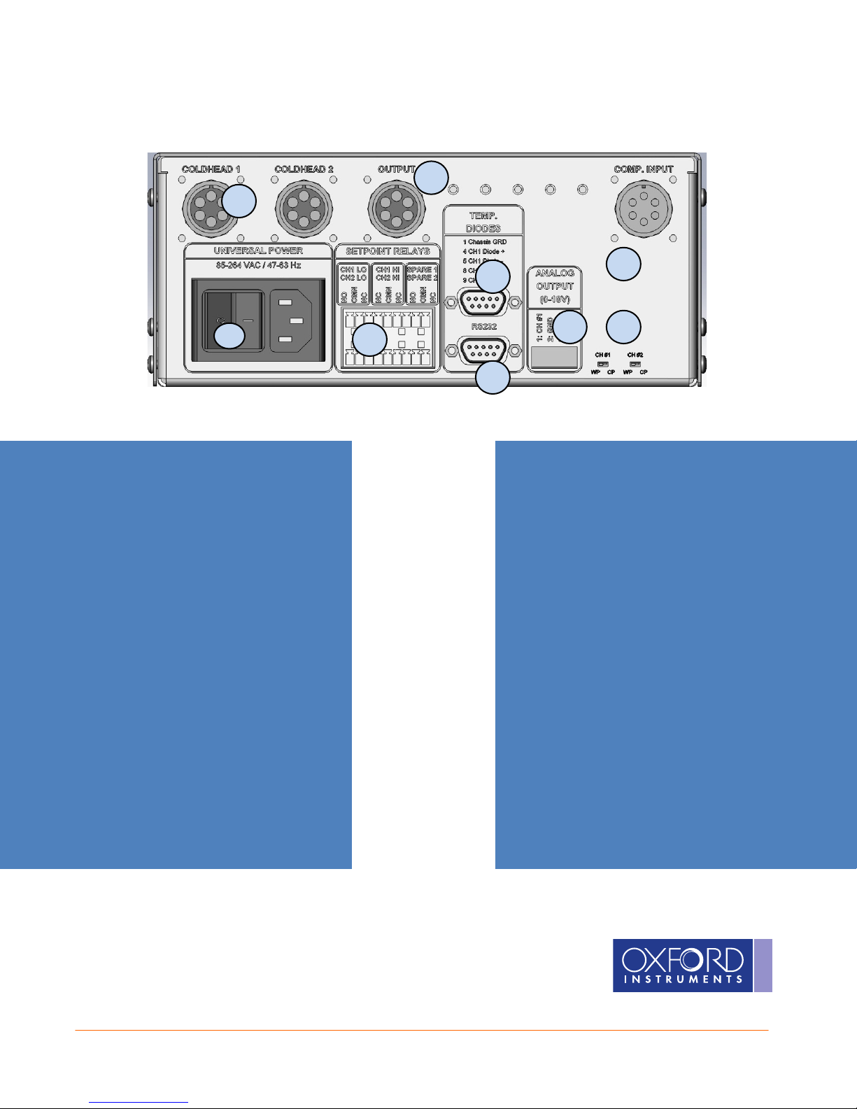
E1000 Installation
E1000 Installation
E1000 InstallationE1000 Installation
8
9
. Universal Power
input accepts 110 or 220 VAC at 50 or 60
Hz
2 – Setpoint Relays. Dry contacts are
provided to trigger external equipment, or
to provide status to control electronics,
such as a PLC. Three relays are provided
for each temperature channel. The top
row connector is controlled by Channel #1
sensor, and the bottom is controlled by
Channel #2. See the setpoint table for a
detailed pin-out.
3 – D-sub 9 Female: Temperature
Sensors. Connect temperature sensor
according to the following pin out:
Pin 1: Shield (GND)
Pin 2: No Connect (NC)
Pin 3: NC
Pin 4: Diode Sensor #1 Positive
Pin 5: Diode Sensor #1 Negative
Pin 6 – 7: NC
Pin 8: Diode Sensor #2 Positive
Pin 9: Diode Sensor #2 Negative
2
3
7
5 6
4
Provides serial interface to a remote serial
device. The serial port is intended to be
used with a standard “straight through”
serial cable (not NULL Modem).
Pin 1: No Connect (NC)
Pin 2: RS-232 Transmit Out
Pin 3: RS-232 Receive In
Pin 4: NC
Pin 5: GND
Pin 6 – 9: NC
5 – Analog Outputs. Analog outputs are
provided for recorder logging, or as status
to a PLC. The outputs provide 0 – 10 V for
each channel.
Pin 1: Channel #1 Voltage Output
Pin 2: GND
Pin 3: Channel #2 Voltage Output
Pin 4: GND
2
• • •
The Business of Science®

6 – Mode Selection
7 – Compressor Power in.
E1000 Rear Panel cont.
E1000 Rear Panel cont.
E1000 Rear Panel cont.E1000 Rear Panel cont.
. 2 miniature slide
switches allow the user to select either
Coldhead or Waterpump mode. In the
coldhead mode, the channel will provide
power to the output at all times and will
operate the relays according to the user
set temperatures. In the Cryopump mode,
power will be supplied at all times to the
coldhead, unless, the manual mode is
selected. To change the Mode of the
E1000, the power switch must be turned
off and back on after changing the
positioni of the switch.
Input drive
power from the compressor. Requires
special drive cable.
8 – Compressor Power Out. Power out to
drive and additional E1000. The power is
fused at 3 amps.
9 – Coldhead out - Output power to the
coldhead or water pump. Uses standard
cryopump drive cable.
3
• • •
The Business of Science®
 Loading...