

Oxford / Hoyer Advance Installation Manual

User
Instruction
Manual &
Warranty
Manuel de
l’utilisateur
et garantie
Manual de
Instrucciones y
Garantía para
el Usuario
Oxford®/Hoyer®Advance
Portable and Folding Patient Lift
Safe working load:
155 kgs / 340 lbs
Benutzerhandbuch
und Garantie
Oxford®/Hoyer®Advance
Mobiler Patientenlifter, klappbar
Zulässige Betriebslast:
155 kgs / 340 lbs
Oxford®/Hoyer®Advance
Lève-personne portatif et pliant
Charge maximale d’utilisation :
155 kgs / 340 lbs
Oxford®/Hoyer®Advance
Elevador portátil y plegable
para pacientes
Carga de trabajo segura:
155 kgs / 340 lbs
294000.10003 Rev. B
English
3
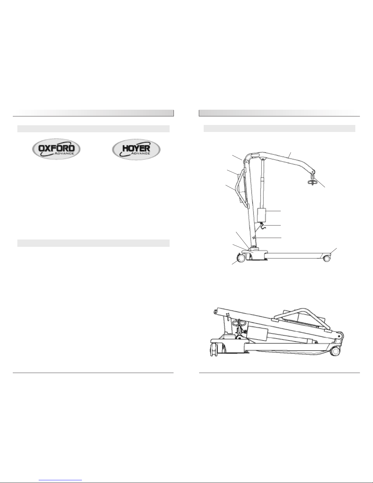
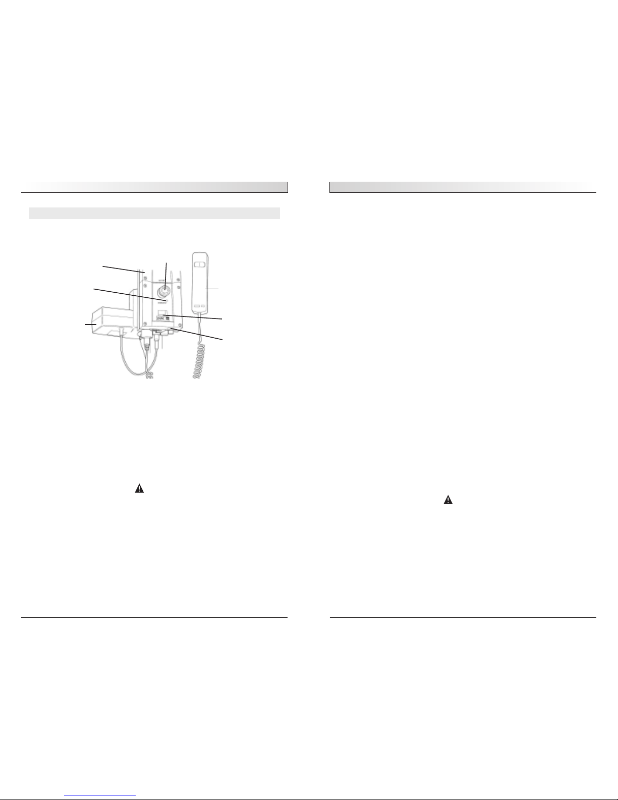
THE OXFORD/HOYER ADVANCE PATIENT LIFT
OXFORD/HOYER ADVANCE LIFT (READY FOR USE)
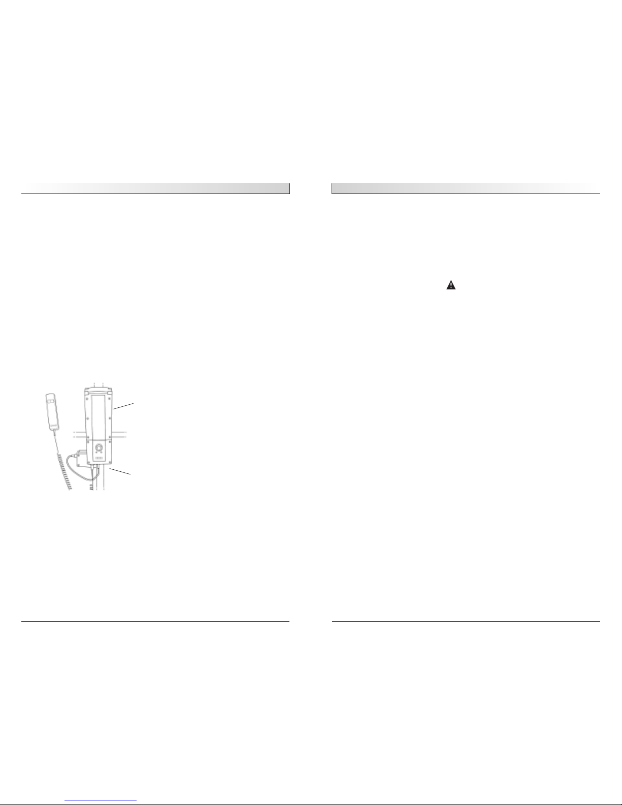
OXFORD/HOYER ADVANCE LIFT (STORAGE POSITION)
English
294000.10003 Rev. B
2
MANUFACTURER’S CONTACT DETAILS
CONTENTS
1. Oxford/Hoyer Advance Patient Lift ........................................................... 3
2. Introduction: The Oxford/Hoyer Advance Patient Lift .................................. 4
3. Assembly and Commissioning Instructions................................................. 5
4. Disassembly.......................................................................................... 7
5. Safety Precautions................................................................................. 10
6. Operating Instructions............................................................................ 12
7. Maintenance Schedule ............................................................................ 16
8. Technical specifications .......................................................................... 18
9. Servicing, repairs, inspections & testing ................................................... 20
EUROPE
Sunrise Medical Ltd
High Street, Wollaston, Stourbridge,
West Midlands
DY84PS UK
+44 (0) 1384 44 66 22
Fax: +44 (0) 1384 44 66 44
www.sunrisemedical.co.uk
USA
Sunrise Medical, Inc
7477 East Dry Creek Parkway
Longmont, CO 80503
303-218-4600
800-333-4000
Fax: 303-263-3390
www.sunrisemedical.com
Boom
Cradle/Spreader Bar
Electric Actuator
Spreader Bar Retaining Cradle
Mast Tightening Knob
Braked Caster
Base Casting
Push Pad
Push Handle
Battery/
Control Pack
Leg Restraining Cord
Leg Extrusion
English
5
ASSEMBLY AND COMMISSIONING INSTRUCTIONS
CARTON CONTENTS
Place the carton in a clear working area and open carefully. The carton contains:
•
OXFORD/HOYER ADVANCE
• WALLET CONTAINING DOCUMENTS
• HANDCONTROL (electric only)
• BATTERY PACK (electric only)
• BATTERY CHARGING LEAD (electric only)
• HYDRAULIC UNIT (hydraulic only)
SAFETY NOTE– The Oxford/Hoyer Advance is heavy and will need to be lifted with care. You may
need assistance to lift the Oxford/Hoyer Advance from the carton.
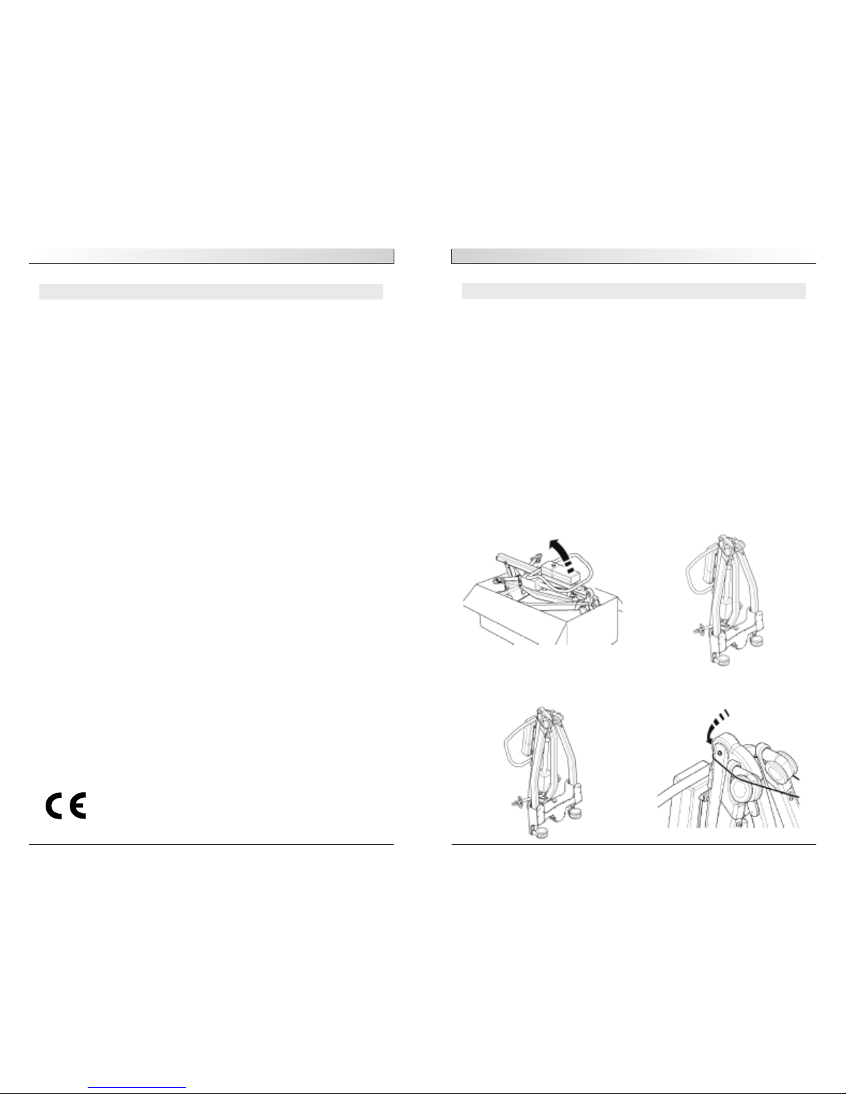
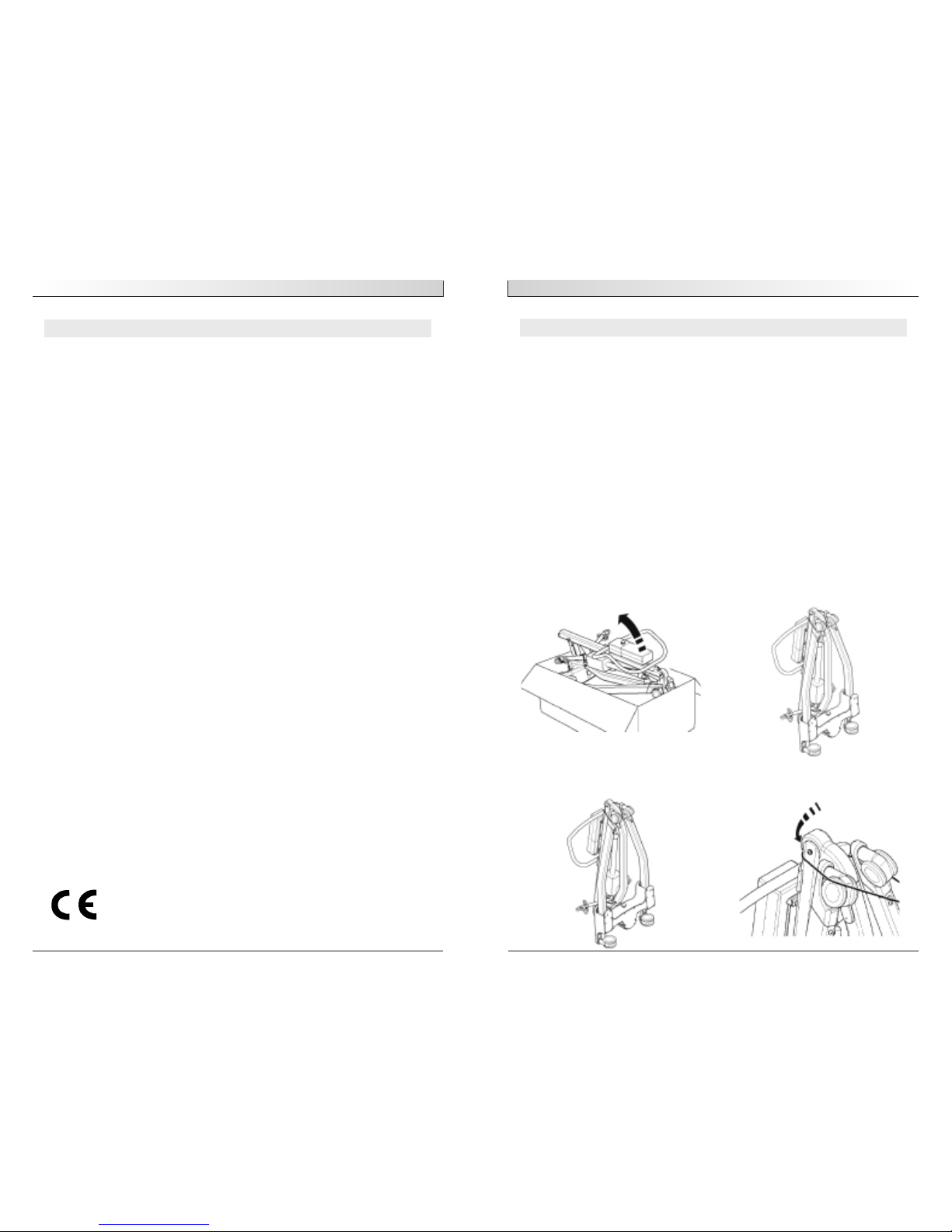
ASSEMBLY INSTRUCTIONS
1. Remove all the parts from the carton and place on the floor, taking care to protect
the finish from damage.
Lift the Advance carefully from the carton. Stand the lift in the upright position (in a
triangular stance).
2. Release the leg and mast assembly by unfastening the restraining strap from the
wheels. This strap will retract neatly into the top of the mast section.
English
294000.10003 Rev. B
4
INTRODUCTION: THE OXFORD/HOYER ADVANCE PATIENT LIFT
ABOUT YOUR LIFT
Statement of Intended Use:
The intended use of the lifting device is to transfer an individual from one resting surface to another (such as a bed to a wheelchair). Moving a person in a sling over ANY
distance is not recommended.
The Oxford/Hoyer Advance is available in two versions, hydraulically operated and electrically operated. This manual covers both Advance models. Each lift is fully assembled,
load tested and certified before being packed/shipped.
The packing consists of a strong, purpose built carton and is used for both export and
domestic markets to ensure the safe arrival of the lift. A number of documents are supplied in a wallet packed with each lift and should be kept safely for future reference.
• TEST CERTIFICATE • USER MANUAL
• DEALER GUARANTEE CARD • CUSTOMER SATISFACTION CARD
The TEST CERTIFICATE is an important document and should be kept for reference purposes. To properly maintain your lift please refer to the maintenance schedule included
in this document. If you are at all unsure what your country’s servicing requirements
are, please check with your dealer and/or a local government agency.
The Oxford/Hoyer Advance is suitable for the following CATEGORIES of lift within the
working parameters of the lifts specified in the TECHNICAL SPECIFICATIONS.
Category A - Wheelchair
Category B - Bed
Category C - Bath (dependent upon setting)
Category D - Toilet/Shower Chair
Category E - Floor
Category F - 90 degree Rotation
The Oxford/Hoyer Advance is suitable for patients in the SITTING, SITTING/RECUMBENT
and RECUMBENT positions. The slings suitable for this device are listed as follows
Oxford/Hoyer Quick fit sling
Oxford/Hoyer Full back sling
Oxford/Hoyer Quick fit deluxe sling
Oxford/Hoyer Long seat sling
Oxford/Hoyer Access sling
The CE mark:
The Oxford/Hoyer Advance carries the CE mark and complies
with th
e f
ollowin
g EC directives:
•
Medical Device Directive (93/42/EEC)
• EMC Directive (89/336/EEC) (Electrics only)
• Low V
oltag
e Dir
ective (73/23/EEC) (Electri
cs only)
294000.10003 Rev. B
294000.10003 Rev. B
English
7
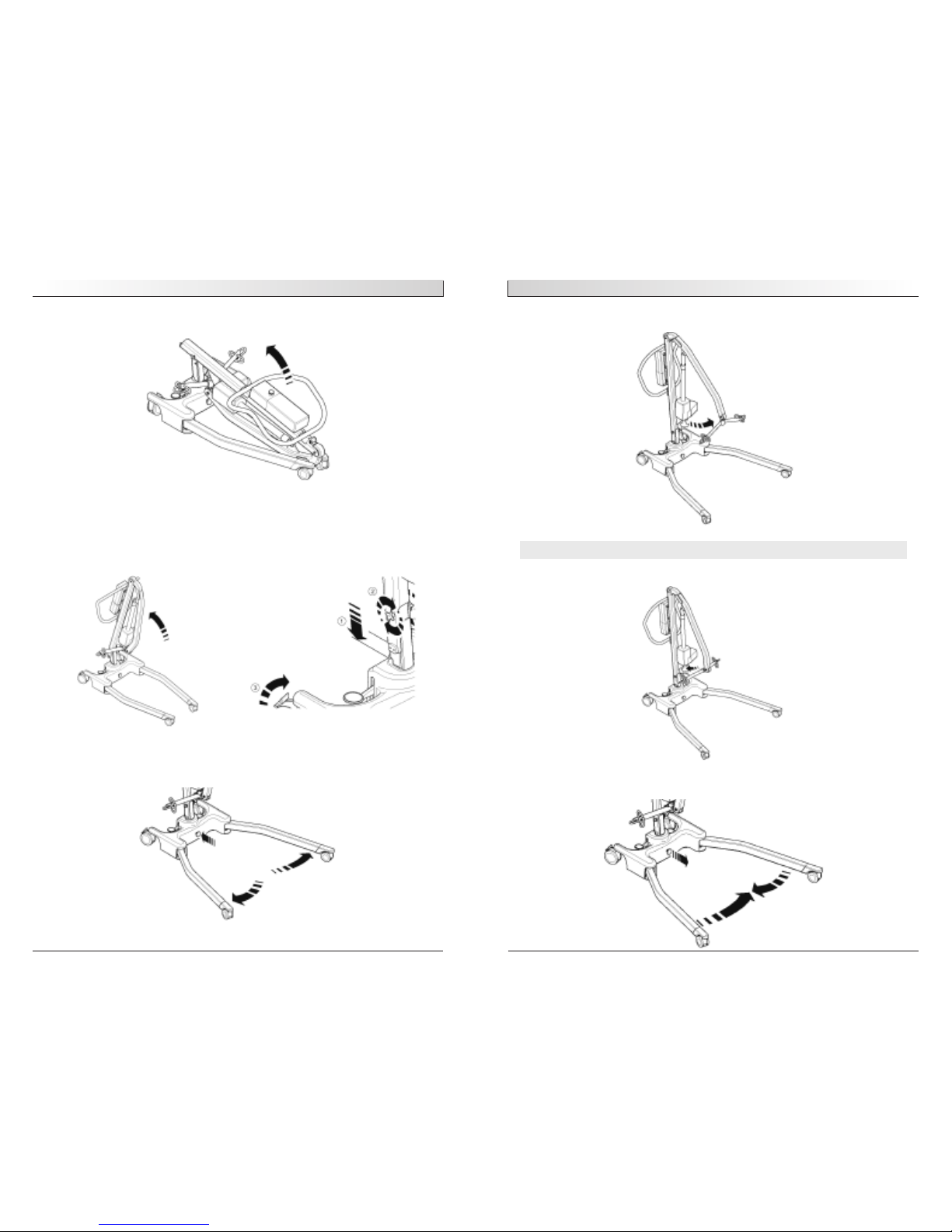
6. Release spreader bar from retaining cradle, and the lift is ready for operation.
DISASSEMBLY
1. Lower the mast to the lowest possible position, then insert spreader bar into
retaining cradle.
2. Release leg-locking device (pulling it away from the cast base), close legs tightly
together.
English
294000.10003 Rev. B
6
3. Lay the Advance flat on the floor (ensure rear castors are securely locked).
4. Lift the mast assembly upright (using the top of the push handle), and drop the
mast into the slot (1), tighten mast lock knobs (2), release braked castors (3).
SAFETY NOTE– Avoid trapping fingers. Keep fingers away from the end of the mast when insert-
ing into the mast slot. Tighten the mast-locking device, and unlock the braked
castors at the rear.
5. Open legs fully. ENSURE leg-locking knob inserts flush against the base casting and
the legs will no longer move freely. The legs will then only operate by the use of the
foot pedal mechanism located at the rear of the base.
294000.10003 Rev. B
English
9
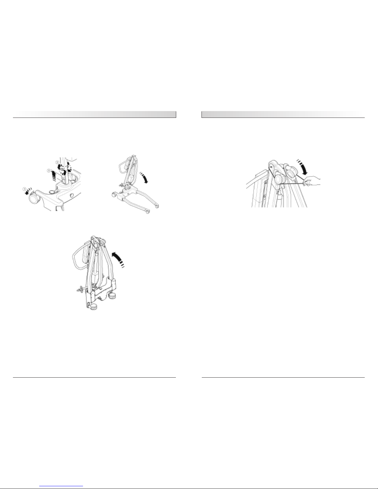
5. Pull the restraining strap sharply upwards and extend over the wheels. (This will
keep the legs, mast and boom neatly together during transit and storage).
NOTE– Care should be exercised when folding/unfolding an Advance as there is a possible danger
of pinching the fingers etc. Please follow the instructions carefully and ask for assistance
if you are unsure of the correct procedure.
ALWAYS CHECK THE FOLLOWING BEFORE OPERATION
• The legs are fully engaged from the stowed position (see assembly instructions,
step 5)
• The mast is fully locked into position (see assembly instructions, step 4)
• The legs of the lift open and close satisfactorily.
• The red emergency stop button, located on the rear of the control box, is in the
OFF (out) position.
• Push the up and down buttons on the hand control and confirm the boom rises
and lowers.
• Fit the power pack to the lift and make sure the latch holding the pack in place
is fully engaged. “Click” in place.
HYDRAULIC MODELS ONLY
• Close the hydraulic unit release valve by turning the knob clockwise on the unit.
NOTE– The release valve requires only minimal tightening to operate and should only be closed
finger tight. DO NOT apply excessive force to the valve knob as this will result in damage
to the valve.
• Pump the handle of the hydraulic unit and confirm the ram raises the boom.
• Open the release valve fully anticlockwise and check the boom descends. An
unloaded boom will not come down under its own weight. It will be necessary to
apply some pressure to the boom before it will descend.
NO
TE–
Th
e r
elease valve is fully open and encounters a positive end stop in less than two full
turns of the knob
English
294000.10003 Rev. B
8
3. Loosen mast locking device (2– not fully) lift the mast and boom assembly (3), and
fold carefully toward the legs. Use the push handle to assist this motion.
NOTE– if you wish to separate the mast and boom completely from the base and legs, undo the
mast locking device fully (remove) and lift the mast and boom completely free from the
base. Be careful not to loose the mast lock device’s, knob and location spindle.
4. Lift the folded Advance upright (using the legs and push handle as a guide) being
careful that the mast and boom stay together as you tilt upright.

294000.10003 Rev. B
English
11
• DO NOT attempt to push/pull a loaded lift over a floor obstruction, which the
castors are unable to ride over.
• NEVER force an operating/safety control. All controls are easy to use and do
not require excessive force.
• DO NOT park a loaded lift on ANY sloping surface.
• DO NOT use electric lifts in a shower.
• DO NOT charge an electric lift in a bathroom or shower room.
• DO NOT lift a patient unless you are trained and competent to do so.
• YOUR lift is for patient lifting. DO NOT use it, or allow it to be used, for any
other purpose.
• DO NOT bump the lift down steps, loaded or unloaded.
• DO NOT attempt to negotiate a loaded lift on a slope, which exceeds 1:12
(approximately 5 degrees).
• DO NOT attempt to negotiate a slope without a second helper being present.
• ALWAYS check the hoist is not charging before moving as the electrical
connection may be damaged.
English
294000.10003 Rev. B
10
SAFETY PRECAUTIONS
Please read and follow the safety precautions listed below. The operation and use of
Oxford/Hoyer patient lifts is simple and straightforward. Following these few basic
safety precautions will make lifting operations easy and trouble free.
READ AND UNDERSTAND THE USER INSTRUCTION MANUAL BEFORE USING
YOUR “ADVANCE” LIFT
WARNING–Important safety information for hazards that might cause serious injury.
CAUTION–Information for preventing damage to the product.
NOTE–Information to which you should pay special attention.
WARNING
• ALWAYS plan your lifting operations before commencing.
• ALWAYS carry out the DAILY CHECK LIST (page 16) before using the lift.
• ALWAYS familiarise yourself with the operating control and safety features of
a lift before lifting a patient.
• DO NOT use a sling unless it is recommended for use with the lift.
• ALWAYS check the sling is suitable for the particular patient and is of the
correct size and capacity.
• NEVER use a sling, which is frayed or damaged.
• ALWAYS fit the sling according to the instructions provided.
• ALWAYS check the safe working load of the lift is suitable for the weight of
the patient.
• ALWAYS carry out lifting operations according to the instructions in the
user manual.
• NEVER disconnect or bypass a control or safety feature because it seems eas-
ier to operate the lift.
• DO NOT lift a patient with the castor brakes on. Always let the lift find the
correct centre of gravity.
• DO NOT attempt to maneuver the lift by pushing on the mast, boom or
patient.
• ALWAYS maneuver the lift with the handle provided.
• ALWAYS lower the patient to the lowest comfortable position before transfers.
• DO NOT push a loaded lift at speeds, which exceed a slow walking pace (3
Kilometer
s/hour 0.8 meter
s/second).
• DO NOT push the lift over uneven or rough ground. Particularly if loaded.
294000.10003 Rev. B
English
13
3. Raising and lowering the boom (electric models)
The movement of the boom is achieved by a powerful electric actuator, which is controlled by a simple hand control unit. The hand control has two buttons with directional arrows UP and DOWN. The actuator stops automatically at the limit of travel in
both directions. The hand control plugs into a socket at the base of the control box.
There is a hook on the rear of the hand control, which allows it to be “parked” on the
mast or boom when not in use.
4. Emergency Stop (Electric only)
The red Emergency Stop Button is located on the rear of the control box and is activated by pressing in. This will cut all power to the lift and only be reset by twisting
the button counterclockwise and releasing.
5. Emergency Lower/Raise
Emergency lower/raise buttons are provided at the rear of the control box. This is operated by inserting the tip of a ball point pen into the button highlighted “lower/raise”.
This will bring the boom down/up should the hand control fail at any time.
6. Mechanical Emergency Down (Electrical Down)
In the case of a complete electrical failure the electric actuator is fitted with mechanical lowering device (RED BOSS). This will only operate when the lift is under load.
The device must be pulled upwards to activate and a slow decent will commence.
7. Batteries
The batteries are protected from deep discharge by a LOW VOLTAGE ALARM. This will
sound when the batteries need recharging and the hand control is being operated. It
will not sound independently of the hand control being operated.
CAUTION: DO NOT
IGNORE THIS WARNING ALARM.
Complete the lifting operation and place the lift on
charge (see charging instructions).
8. Raising and lowering the boom (hydraulic models)
WARNING
Never loosen or unscrew the retaining bolt of the hydraulic jack unless you
are an authorised competent engineer. Never load whilst user needs to rotate
hydraulic jack. If the user intends to rotate the jack strongly, it may impact
the patient or cause unforseen danger to patient and/or caregiver.
Th
e r
aisin
g and lowering of the boom is achieved by a powerful hydraulic ram, which is
operated by two simple controls. The release valve, which is identified by a silver star
shaped knob, and the pump handle which is a long lever on the side of the hydraulic
unit to raise the boom. The valve is closed by gently turning the knob fully clockwise.
When closed, pump the long handle with smooth even strokes for maximum effect. The
handle strokes from an upright position through an arc of 90 degrees. Leave the handle in the upright position when not in use.
English
294000.10003 Rev. B
12
OPERATING INSTRUCTIONS
OPERATING CONTROLS FOR THE OXFORD/HOYER ADVANCE
OPERATING INSTRUCTIONS
1. Leg adjustment
The legs on the Oxford/Hoyer Advance are adjustable for width. The legs can be
opened to enable access around armchairs or wheelchairs. For transferring and negotiating narrow doorways and passages the lift legs should be in the closed position.
To achieve the adjustment, the leg adjuster pedal, located at the rear of the base, is
compressed right (DOWN) to open the legs outwards and left (UP) to close the legs.
The adjustment can be carried out with the patient in the lift, but whether loaded or
unloaded the adjustment should be made when the lift is moving.
WARNING
Never lift with the legs in the closed/transport position. The closed position
is for storage and transport only.
2. Castors and Braking
The lift has two br
aked castors, which can be applied for parking. When lifting, the
castors should be left free and un-braked, so that the lift will then be able to move to
the centre of gravity of the lift. DO NOT apply the brakes because if the brakes are
applied the patient might swing to the centre of gravity and this may prove disconcertin
g an
d uncomfortable.
Emergency
Stop Button
Hand Control
Charger Point
Battery Indicator
Actuator
Motor
Emergency
Lower/Raise
Detachable Battery
Pack
294000.10003 Rev. B
English
15
Off Board Charging Option
There is an off board charging option on the Advance hoist. This can be activated by
inserting the relevant charge lead into the controller base and connecting this lead to
the mains supply. Charging is then automatic. To return the lift back to service simply
remove the lead. The battery indicator will then highlight the amount of charge that
has been provided to the batteries. It is advised to charge the batteries fully before
returning the lift to service.
WARNING
• Do NOT use the lift whilst charging is taking place.
• Be careful not to trip over the charge lead.
• WARNING check the hoist is not charging before moving as the electrical
connection may be damaged
• CAUTION: Keep the batteries fully charged. Place the lift on charge whenever
it is not in use. The charger will not allow the batteries to “overcharge”.
• CAUTION: Never run the batteries completely flat. If the audible warning
sounds, complete the lifting operation in hand and place the lift on charge.
• CAUTION: Never store the lift for long periods without regular charging
throughout the storage period.
• CAUTION: Always make sure the mains power to the charger is switched off
before connecting or disconnecting the charger to or from the lift.
• CAUTION: Never leave the charger plugged into the lift with the mains
power off.
• CAUTION: Never disconnect the charger plug by pulling on the cable.
• Do not charge an electric lift in a bathroom or shower room.
English
294000.10003 Rev. B
14
DO NOT force the handle beyond the upper or lower stops. The hydraulic unit can be
rotated to allow the handle to be used from either side of the lift. To lower the boom,
turn the release valve anticlockwise. The release valve is progressive, the more it is
opened the faster the descent. The valve is restricted so even when fully open the
descent is controlled. This facility allows for a “hands free” descent. If the release
valve is opened a fraction (a quarter turn) a very slow speed of descent will allow the
caregiver to work “hands free” while assisting or comforting the patient. REMEMBER to
close the release valve before commencing lifting operations. The release valve only
requires gentle pressure to open or close. DO NOT apply excessive force to the release
valve, either to close or to open. It is not necessary and will only damage the valve.
9. Slings
The selected sling is attached to the spreader bar hooks, each sling is supplied with
instructions. Please study the instruction guide for the lifter and sling before using. Once
the correct sling has been selected for the patient, attach it to the spreader bar hooks.
CHARGING INSTRUCTIONS FOR THE OXFORD/HOYER ADVANCE LIFT
On Board Charging Option
The batteries are located in the power pack and are charged through a socket at the
base of the control box.
1. Insert the power supply plug into the charge point at the base of the control box.
The plug is inserted with a straight push. DO NOT twist the plug in the socket.
2. Plug the charger mains lead/cord into a suitable mains/power outlet and switch
the mains/power supply ON.
3. Charging is fully automatic. The LCD indicator indicates the status of the charging. Note: Even if the charger is left plugged in for extended periods it will not
allow the batteries to “overcharge”.
4. To return the lift to service, switch OFF the mains supply, pull the charger socket
out and disengage from the mains supply
Removable Battery Pack
Charge Point

294000.10003 Rev. B
English
17
English
294000.10003 Rev. B
16
MAINTENANCE SCHEDULE FOR THE OXFORD/HOYER ADVANCE
All Oxford/Hoyer products are designed for minimum maintenance, however some
safety checks and procedures are required. A schedule of DAILY tasks is detailed below.
A list of replacement parts is available upon request.
DAILY CHECK LIST
Sunrise Medical strongly recommends the following checks be carried out on a daily
basis and before using lift.
- MAKE sure the lift moves freely on its castors.
- MAKE sure the spreader bar is free to rotate and swing. Check the spreader bar is
firmly attached to the boom.
- EXAMINE the sling hooks on the spreader bar and side suspenders for excessive
wear. If in doubt - do not use.
- EXAMINE slings for fraying or other damage. DO NOT use any sling if damaged
- MAKE sure the legs open and close correctly.
- OPERATE the hand control or the hydraulic unit to confirm the boom raises and
lowers satisfactorily.
- CONFIRM the lift is not giving a low battery alarm when the hand control is
operated (electric lifts only). If the alarm sounds DO NOT use and place on
charge immediately.
- ON electric powered lifts check the operation of the emergency stop button.
- ON hydraulically operated lifts check for hydraulic fluid leakage. Any leakage
should be reported to a service engineer immediately and the lift should not be
used until it has been repaired.
MAINTENANCE, INSPECTION AND TEST
Sunrise Medical recommends a thorough inspection and test of the Oxford/Hoyer
Advance lift and lifting accessories; slings, etc. are carried out on a regular basis.
Inspection frequency varies from country to country, so you must check with your local
government agency how often an inspection is required. The examination and test
should be conducted according to the recommendations and procedures below.
Whenever possible Sunrise Medical recommends maintenance, inspection and certified
testing is carried out by authorised service agent / dealers only.
NOTE– These recommendations are in compliance with the requirements of 1998 No2307 Health
and Safety: The Lifting Operations and Lifting Equipment Regulations 1998. This is a UK
regulation. Outside the UK please check your local country requirements.
1. SPREADER BAR: Check the spreader bar for freedom of rotation
33
and swing. Check for wear on the central pivot. Check for firm
attachment to the boom.
2.
BOOM: Check the attachment of the boom to the mast. Make sure
33
there is only minimal side movement of the boom and the boom
is free to rotate on the boom bearing.
3.
MAST: Check the operation of the mast-locking device. Make sure
33
the mast fully engages into the socket. Check the bottom actuator
or hydraulic unit mounting.
4.
ACTUATOR (electric only): The actuator should require no
3
maintenance other than checking for correct operation and
listening for unusual noise.
5.
POWER PACK (electric only): Check the function of the
33
emergency stop button and emergency down/up.
6.
BATTERIES (electric only): The batteries are housed in the power
3
pack and should not require maintenance other than the regular
charging as detailed in the charging instructions. Check that the
connections remain clean.
7.
HYDRAULIC UNIT The hydraulic unit should require no
33
maintenance other than checking for correct operation and
leakage of hydraulic fluid.
8.
LEG ADJUSTMENT: Check the legs operate in both full
33
extensions (inward/outward).
9.
CASTORS: Check all castors for firm attachment to the legs.
33
Check for free rotation of the castor and the wheels.
10.
CLEANING: Clean with ordinary soap and water and/or any hard
3
surface disinfectant. Harsh chemical cleaners or abrasives should
be avoided as these may damage the surface finish of the lift.
Avoid wetting any of the electrical parts.
11.
LOAD TEST: The load test should be carried out in accordance
3
with the manufacturer's test procedures.
12.
BASE AND WHEELS: Ensure base is even and level
3
3
(all four wheels are on the floor).
13. SLINGS: Check for wear and fraying. 3
14. LUBRICATION: Oil pivot joints, including mast and boom
3
connections, pedal assembly, spreader bar joint (only if required).
*THESE CHECKS SHOULD INCLUDE:
Before Use
Initially
Service
Intervals

294000.10003 Rev. B
English
19
ELECTRICAL SPECIFICATIONS
BATTERIES 12 volt Rechargeable sealed lead acid type
BATTERY CAPACITY 3.2 Ampere hours
CHARGER RATED INPUT 230Vac 50/60Hz
CHARGER RATED OUTPUT 27.4/29.0 VDC@0.8A
ELECTRIC SHOCK PROTECTION
CHARGER - CLASS II
LIFT - INTERNAL POWER SOURCE
DEGREE OF SHOCK PROTECTION
CHARGER - TYPE B
LIFT - TYPE B
SLING USE/TYPE OXFORD/HOYER GREY LOOPED
INTENDED OPERATING ENVIRONMENT: .................>+5˚ <+40˚
Outside this environment functionality and safety may be compromised.
English
294000.10003 Rev. B
18
OXFORD/HOYER ADVANCE TECHNICAL SPECIFICATIONS
ELECTRIC AND HYDRAULIC MODELS
Specification Electric Hydraulic
Safe Working Load 341 lbs. 155Kgs 341 lbs. 155Kgs
Maximum Overall Length 51 inches 1300mm 49.2 inches 1250mm
Minimum Overall Length 49 inches 1250mm 47.2 inches 1200mm
Maximum Overall Height 73 inches 1860mm 72.6 inches 1845mm
Minimum Overall Height 53.5 inches 1360mm 53.1 inches 1350mm
Folded Dimensions
Height 17.1 inches 450mm 16.9 inches 470mm
Depth 46.4 inches 1180mm 46.5 inches 1230mm
Width 21.6 inches 550mm 23.0 inches 550mm
Spreader Bar Max. Height 66.5 inches 1690mm 64.6 inches 1640mm
Spreader Bar Min. Height (usable) 15.3 inches 390mm 15.4 inches 390mm
Height at Maximum Reach 46 inches 1170mm 33.5 inches 850mm
Reach at Maximum Height 25.6 inches 650mm 28.0 inches 710mm
Reach at Minimum Height 13.7 inches 350mm 15.4 inches 390mm
Maximum Reach* 32.8 inches 835mm 33.5 inches 850mm
Turning Radius 55.9 inches 1420mm 41.0 inches 1040mm
Legs Open - External Width 42.5 inches 1080mm 43.7 inches 1110mm
Legs Open - Internal Width 39.3 inches 1000mm 45.7 inches 1160mm
Legs Closed - External Width 26.3 inches 670mm 25.2 inches 640mm
Legs Closed - Internal Width 22.4 inches 570mm 21.7 inches 550mm
Overall Height of Legs 4.5 inches 115mm 4.7 inches 120mm
Ground Clearance 1.1 inches 30mm 1.2 inches 30mm
Front Twin Castors 3.0 inches 75mm 3 inches 75mm
Rear Braked Castors 3.9 inches 100mm 4 inches 100mm
*Reach = centre of spreader bar to the front of the mast
Weights
Mast, Base & Boom Assembly 63.1 lbs. 28.9kgs 63.7 lbs. 26.8kgs
Power Pack 6.2 lbs. 2.8kgs N/A
Total 69.9 lbs. 31.7kgs 59 lbs. 26.8kgs
Base Assembly (not incl. battery) 32.8 lbs. 14.9kgs 32.9 lbs. 14.9kgs
Mast & Boom (not incl. battery) 30.9 lbs. 14.0kgs 26.3 lbs. 11.9kgs
All measurements are within a +5/-5 degree of tolerance.

English
294000.10003 Rev. B
20
SERVICING, REPAIRS, INSPECTIONS AND TESTING
Sunrise Medical has an established network of reputable distributors and dealers
who will be pleased to handle all your purchasing, warranty, repair and maintenance
enquire.
Included with each patient lift is a prepaid Customer Satisfaction card. Please take the
time to fill it in and return it to your local Sunrise Medical office. Our products are
guaranteed for a period of 24 months from the date of purchase.
This guarantee covers the lifts major structure, actuator, control box, handset,
and battery.
In the United Kingdom, it is recommended that all of our products be commissioned
by your dealer. The dealer or distributor operates the warranty programme, so it is
important to keep a record of their name address and telephone number so they can
be contacted should any problem arise.
If you are in doubt where your lift was purchased, Sunrise Medical can trace the
supplier if you quote the serial number of the lift.
REMEMBER Contact your distributor for purchases, Warranty, repairs, servicing and
certified maintenance.
Your distributor:

294000.10003 Rev. B
Français
23
LE LÈVE-PERSONNE OXFORD/HOYER ADVANCE
LÈVE-PERSONNE OXFORD/HOYER ADVANCE (PRÊT À L’EMPLOI)
LÈVE-PERSONNE OXFORD/HOYER ADVANCE (EN POSITION DE RANGEMENT)
Français
294000.10003 Rev. B
22
COORDONNÉES DU FABRICANT
TABLE DES MATIÈRES
1. Le lève-personne Oxford/Hoyer Advance.................................................... 23
2. Introduction: Le lève-personne Oxford/Hoyer Advance ................................ 24
3. Instructions de montage et de mise en service .......................................... 25
4. Démontage........................................................................................... 27
5. Consignes de sécurité............................................................................. 30
6. Instructions de fonctionnement ............................................................... 32
7. Périodicité d’entretien de l’appareil Oxford/Hoyer Advance........................... 36
8. Spécifications techniques ....................................................................... 38
9. Révisions, réparations, inspections et essais .............................................. 40
EUROPE
Sunrise Medical Ltd
High Street, Wollaston, Stourbridge,
West Midlands
DY84PS UK (Royaume-Uni)
+44 (0) 1384 44 66 22
Fax: +44 (0) 1384 44 66 44
www.sunrisemedical.co.uk
États-Unis
Sunrise Medical, Inc
7477 East Dry Creek Parkway
Longmont, CO 80503
303-218-4600
800-333-4000
Fax: 303-263-3390
www.sunrisemedical.com
Flèche
Berceau / barre
d’écartement
Actionneur électrique
Berceau de retenue de la barre
d’écartement
Bouton de serrage du mât
Roulette à frein
Base moulée
Bouton-poussoir
Poignée de
manœuvre
Bloc d’alimentation /
commandes
Corde de retenue
des pieds
Partie extrudée du pied
294000.10003 Rev. B
Français
25
INSTRUCTIONS DE MONTAGE ET DE MISE EN SERVICE
CONTENU DE LA BOÎTE
Placez la boîte sur une surface bien dégagée et ouvrez-la avec précaution. Elle contient :
• L’APPAREIL OXFORD/HOYER ADVANCE
• UNE POCHETTE CONTENANT DES DOCUMENTS
• UNE COMMANDE MANUELLE (modèle électrique uniquement)
• BATTERIES (modèle électrique uniquement)
• CHARGEUR DE BATTERIES AU PLOMB (modèle électrique uniquement)
• UNE UNITÉ HYDRAULIQUE (modèle hydraulique uniquement)
REMARQUE CONCERNANT LA SÉCURITÉ– L’appareil Oxford/Hoyer Advance est lourd et devra
être soulevé avec précaution. Il est possible que vous soyez obligé(e) de vous faire aider pour
soulever l’appareil Oxford/Hoyer Advance et le sortir de la boîte.
INSTRUCTIONS DE MONTAGE
1. Retirez toutes les pièces de la boîte et placez-les par terre, en prenant soin de pro-
téger le fini.
Avec précaution, soulevez l’appareil Advance de l'emballage. Mettez le lève-personne à
la verticale (de manière ã former un triangle).
2. Dégagez le pied et le mât en détachant la sangle de retenue des roues. Cette sangle
rentrera dans le haut de la section du mât.
Français
294000.10003 Rev. B
24
INTRODUCTION : LE LÈVE-PERSONNE OXFORD/HOYER ADVANCE
À PROPOS DE VOTRE LÈVE-PERSONNE
Déclaration d’utilisation prévue :
Ce dispositif est prévu pour permettre le transfert d’une personne entre deux surfaces
d’appui (par exemple, d’un lit à un fauteuil roulant). Il est déconseillé de déplacer une
personne à l’aide de courroies, sur QUELQUE distance que ce soit.
Le modèle Oxford/Hoyer Advance est offert en version hydraulique et en version électrique.
Le présent manuel couvre les deux modèles Advance. Chaque lève-personne est entièrement
monté, soumis à un essai de charge et certifié avant d'être emballé / expédié.
L’emballage se compose d’une boîte en carton robuste construite spécialement pour les
expéditions intérieures et les exportations qui permet de garantir l’arrivée de l’appareil intact
à destination. L’emballage de chaque lève-personne comprend une pochette contenant un
certain nombre de documents qui doivent être conservés en lieu sûr pour référence future.
• CERTIFICAT D’ESSAI • MANUEL D’UTILISATION
• CARTE DE GARANTIE DU REVENDEUR • CARTE DE SATISFACTION
Le CERTIFICAT D’ESSAI est un document important qui doit être conservé à titre de
référence. Pour entretenir correctement votre lève-personne, veuillez vous référer au
tableau de périodicité d'entretien dans ce document. En cas d’incertitude concernant
les normes d’entretien locales, veuillez vous renseigner auprès de votre revendeur et /
ou d’un organisme gouvernemental local.
Le lève-personne Oxford/Hoyer Advance convient pour les CATÉGORIES de levage suivantes,
dans les limites des paramètres appareils figurant dans les SPÉCIFICATIONS TECHNIQUES.
Catégorie A – Fauteuil roulant
Catégorie B - Lit
Catégorie C – Bain (dépend du réglage)
Catégorie D – Toilette / chaise de douche
Catégorie E - Plancher
Catégorie F – Rotation à 90 degrés
L’appareil Oxford/Hoyer Advance convient pour des patients ASSIS, ASSIS/ALLONGÉS ET
ALLONGÉS. Les courroies convenant à ce dispositif sont décrites ci-après :
Oxford/Hoyer, courroie Quick Fit (à montage rapide)
Oxford/Hoyer, courroie Full Back (arrière)
Oxford/Hoyer, courroie Quick Fit (à montage rapide) de luxe
Oxford/Hoyer, courroie de siège longue
Oxford/Hoyer, courroie d’accès
Marque CE :
L’appareil Oxford/Hoyer Advance porte la marque CE et il est conforme aux directives CE suivantes :
• Medical Device Directive (appareils médicaux) 93/42/CEE
• Directive EMC (89/336/CEE) (appareils électriques uniquement)
•
Dir
ective relative aux basses tensions (73/23/CEE)
(appareils électriques uniquement)
 Loading...