

Page 1
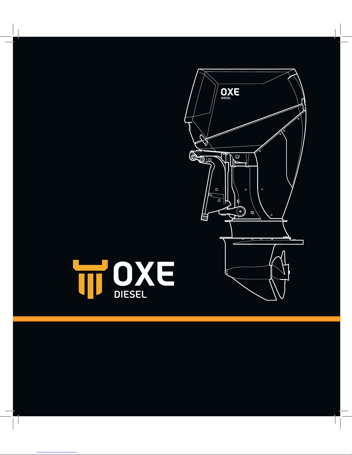
USER MANUAL
OXE 200 HP
Page 2
“THE OXE POWER HEAD IS A WELL PROVEN DIESEL
ENGINE INHERENTLY MORE EFFICIENT THAN GASOLINE
ENGINES CONTRIBUTING TO LOW FUEL CONSUMPTION”
Page 3

Overview
3
INTRODUCTION
Publication No: ODM1005
Maintenance
Operating
Technical data
Page 4

Page 5
55
CONTENT
Overview ____________________________ 1
About this manual ___________________ 1
Safety information ___________________ 2
Symbols and signs _________________ 2
Rotating parts _____________________ 2
Hot parts _________________________ 2
Electric parts _____________________ 2
Engine shut-off switch and cord ______ 2
Engine exhaust emissions ___________ 3
Modifications ________________________ 3
Accessories ______________________ 3
Safe boating ________________________ 3
Boater’s responsibilities _____________ 3
Boat horse power capacity __________ 3
Boat performance capacity __________ 3
Warning and information labels _________ 4
Main components ____________________ 6
Instrumentation _____________________ 8
control head ________________________ 8
Control head operation ________________ 9
Control lamp ______________________ 9
Indicator dimming feature ___________ 9
Neutral indicator lamp ______________ 9
Control head range _________________10
Neutral throttle warmup ____________10
Low speed control _________________11
Trolling mode _____________________11
Adjustable lever feel _______________12
Outboard Installation _________________13
Mounting the outboard ________________14
Mounting height ___________________14
Engine connector __________________15
Connecting the battery ______________15
Connecting fuel line ________________16
Engine shut-off cord ________________16
Breaking in the engine ________________16
Operating __________________________ 17
Before start-up ______________________17
Checking the fuel level ______________ 17
Controls _________________________17
Outboard _________________________ 17
Filling fuel ________________________18
Check engine oil, hydraulic oil and
belt oils __________________________18
Check fluid level in power trim and
tilt unit __________________________ 20
Starting the outboard _________________21
Prestart checks ___________________21
Warming up the engine ____________ 22
Shiing _________________________ 23
Stopping the engine _______________ 23
Power trim operation ________________ 24
Adjusting the trim angle ____________ 25
Adjusting the boat trim ____________ 25
Bow up _________________________ 25
Bow down ________________________26
Technical data Maintenance
Operating Overview
Overview
Operating
Maintenance
Technical data
Page 6

Power tilt operation __________________26
Procedure for tilting up ____________ 27
Procedure for tilting down __________ 27
Power trim and tilt switch on engine
cowling _________________________ 27
Maintenance ________________________ 29
Outboard care ______________________ 29
Owners responsibility ________________ 29
Transporting the outboard ____________ 29
Storing the outboard _________________ 30
Winterization of the outboard _______ 30
Cleaning the outboard ________________31
Flushing the power unit ______________ 32
Checking and other maintenance _______ 33
Check the intake system ___________ 33
Check the air filter ________________ 33
Check the engine for oil leakage _____ 33
Check drive belts _________________ 33
Check the battery _________________ 33
Check the electric system __________ 33
Check the fuel system _____________ 34
Priming the fuel system ____________ 34
Check cooling system _____________ 35
Check water intake ________________ 36
Check coolant level and mixture _____ 36
Check power trim and tilt system ____ 37
Check the propeller _______________ 38
Check the top cowling _____________ 39
Check the cowling sealing __________ 39
Check painted surfaces ____________ 39
Inspect anodes ___________________ 40
Change fluids and filters ______________ 42
Change fuel filter _________________ 42
Replace hydraulic oil and filter _______ 43
Clean seawater strainer ____________ 44
Replace air filter __________________ 44
Change engine oil _________________ 45
Replace engine oil filter ____________ 45
Change lower belt oil ______________ 46
Change coolant ____________________ 47
Replace thermostat _______________ 48
Replace propeller __________________49
Lubricating and greasing ______________51
Power trim and tilt unit _____________51
Maintenance schedule ________________ 52
Fault codes _________________________59
Trouble shooting ____________________ 62
Technical data ______________________63
Recommended fluids and grease _______ 64
Diesel fuels ________________________ 65
Page 7

1
OVERVIEW
ABOUT THIS MANUAL
This manual provides you with the information
you need to know about starting, operating and
maintaining your OXE Diesel engine.
Read this manual carefully and learn how to
operate your outboard properly. Always contact
your dealer if you have any questions.
Using and attending the engine properly will
preserve its qualities for a long operating
life. Follow the instructions in this manual on
operating this engine and carry out inspections
as described on a regular basis.
Cimco Marine AB
Metallgatan 19a
SE-262 72 Ängelholm, Sweden
+46 (0)431-371130
[email protected]
Technical data Maintenance
Operating Overview
Page 8
2
OVERVIEW
SAFET Y INFORMATION
Do note remove or replace the top cover with
the engine running.
Hot parts
!
DANGER
During and aer operation, engine parts
could be hot enough to cause burns. Do not
touch any parts under the top cover until the
engine has cooled off.
Electric parts
!
DANGER
Do not touch any electrical parts while
starting the engine. They can cause shock or
electrocution.
Engine shut-off switch and cord
!
DANGER
The purpose of a lanyard stop switch is to
stop the engine when the operator moves far
enough away from the operator’s position to
activate the switch.
Attach the engine shut-off cord so that the
engine stops if the operator falls overboard
or leaves the helm.
When activating the engine shut-off switch
the engine will stop immediately, but the
boat will continue to coast for some distance
depending on velocity and degree of any turn
at shut down.
Safety and operating information that is
practiced, along with good common sense,
can help prevent personal injury and product
damage.
Symbols and signs
!
DANGER
This indicates a hazardous situation which,
if not avoided, will result in death or serious
injury.
!
WARNING
This indicates a hazardous situation which, if
not avoided, could result in death or serious
injury.
!
CAUTION
This indicates a hazardous situation which,
if not avoided, could result in minor or
moderate injury.
NOTE! Important information
Rotating parts
!
DANGER
Rotating parts can cause cuts, mutilation or
strangulation.
Hands, feet, hair, jewelry, clothing, PFDstraps, etc. can become entangled with
internal rotating parts of the engine or
exposed moving parts.
Page 9
3
Engine exhaust emissions
!
WARNING
Inhaling engine exhaust gases can result
in carbon monoxide poisoning, which can
lead to unconsciousness, brain damages, or
death. Avoid exposure to carbon monoxide
gas.
Stay clear from exhaust areas when the
engine is running. Keep the boat well
ventilated.
MODIFICATIONS
!
WARNING
Do not attempt to modify the outboard.
Modifications may reduce safety and
reliability, and render the outboard unsafe or
illegal to use.
Accessories
The outboard must not be modified in any
way except with accessories and service kits
approved by the manufacturer.
SAFE BOATING
Boater’s responsibilities
It is always the operator (driver) that is
responsible for the correct and safe operation
of the boat and the safety of its occupants and
general public. We strongly recommended that
each operator reads and understands the entire
manual before operating the outboard.
Be sure that at least one additional person
onboard is instructed in the basics of starting
and operating the outboard and boat handling in
case the driver is unable to operate the boat.
Boat horse power capacity
Exceeding the boat’s maximum power
rating can cause serious injury or death. Any
overpowering of the boat can affect boat control
and flotation characteristics or break the
transom.
Do not install an outboard that exceeds the
boat’s maximum power and weight rating.
Boat performance capacity
Do not overpower or overload your boat.
Most boats will carry a required capacity plate
indicating the maximum acceptable power
and load as determined by the manufacturer.
If in doubt, contact your dealer or the boat
manufacturer.
Technical data Maintenance
Operating Overview
Page 10
4
OVERVIEW
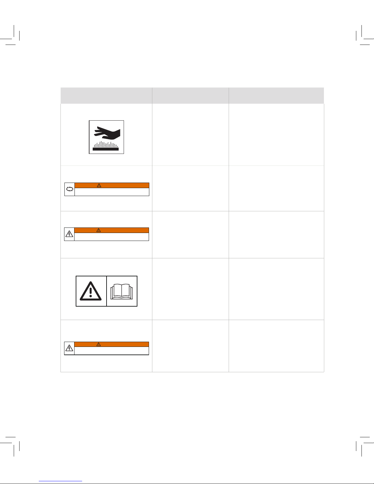
Label Information Location
Heat warning label
30-0300-003
Warning for hot surfaces, which
could result in burns.
1. Placed on the turbo pressure pipe.
2. Placed on the lower part of the
intercooler, near the primary belt
housing.
Rotation warning label
WARNING
Keep hands, hair, and clothing away from
rotating parts while the engine is running.
30-0300-004CIMCO MARINE AB
Warning for rotating parts.
1. Placed on the lower timing belt cover,
on engine front.
2. Placed next to the upper belt housing.
Electrical warning label
WARNING
Do not touch or remove electrical parts when
starting the engine or during operation.
30-0300-005CIMCO MARINE AB
Warning for electrical hazards. Placed on the ECU-bracket.
Read manual label 1
30-0300-009CIMCO MARINE AB
A reminder of the importance to
read manuals prior to the initial
use of equipment or machinery.
The manual contains information
needed for proper operation,
maintenance and care.
Placed on the upper cowling, next to the
trim and tilt button.
Read manual label 2
WARNING
Do not touch or remove electrical parts when
starting the engine or during operation.
30-0300-005CIMCO MARINE AB
Placed on top of the timing belt cover.
WARNING AND INFORMATION LABELS
Page 11
5
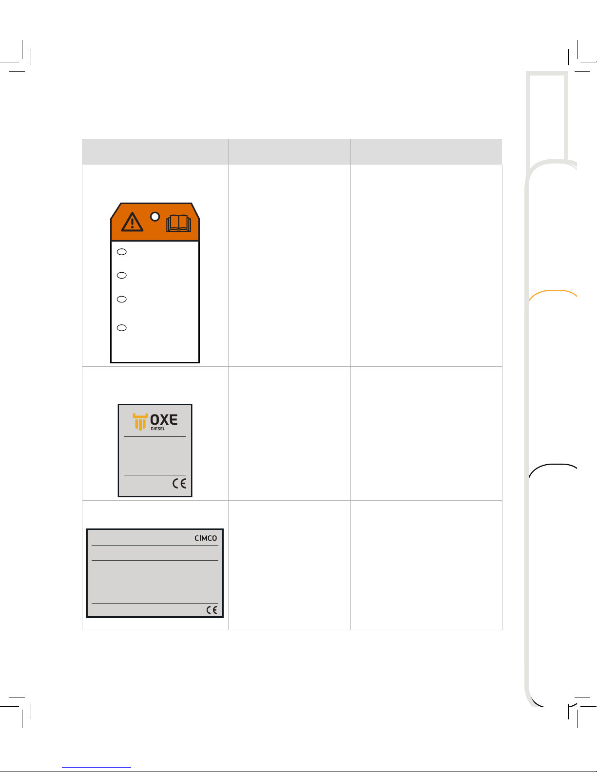
Label Information Location
Read manual label 3
WARNING!
Locate and read operator’s
guide, follow all instructions
and warnings.
AVERTISSEMENT!
Localiser et lire le guide de
l’opèrateur. Suivre tous les
consignes et avertissements.
WARNUNG!
Betreibsanleitung ausfindig
machen und lesen. Alle
Anweisungen und
Warnhinweise befolgen.
¡ADVERTENCIA!
Ubicar y leer la guía del
operador. Atenerse a todas
las instrucciones y mensajes
de advertencia.
30-0300-007CIMCO MARINE AB
EN
FR
ES
DE
A reminder of the importance to
read manuals prior to the initial
use of equipment or machinery.
The manual contains information
needed for proper operation,
maintenance and care.
Hanging underneath the cowl, near the
engine connector.
Identification label
MODEL: OXE 200
MODEL NR: P3XL200
SERIAL NR:
BLOCK NR:
D.O.M:
MADE IN SWEDEN
CIMCO MARINE AB
30-0300-001
00001
17B68420
2016-08-25
1. Placed on the starboard side of the
engine, just below the middle cowling.
2. Placed on page 2 in the Service Book.
Emission label
THIS OUTBOARD ENGINE COMPLIES WITH 2016 U.S EPA 40CFR PART 1042,
IMO 40CFR PART 43 EXHAUST REGULATIONS
• APPLICATION: COMMERCIAL
CATEGORY 1, PROPULSION WITH
FIXED-PITCH PROPELLERS
• REFER TO OWNER’S MANUAL FOR
MAINTENANCE SPECIFICATIONS AND
ADJUSTMENTS
• ULS DIESEL FUEL ONLY
MODEL: OXE 200
MODEL YEAR: 2016
FAMILY: GCABN02.0OXE
MAX POWER: 200HP / 149kW
MAX SPEED: 4300RPM
DISPLACEMENT: 1956 CC
STANDARD FELs: NO+HC 5,8 g/kWh
PM 0,15 g/kWh
EMISSION CONTROL INFORMATION
MADE IN SWEDEN CIMCO MARINE AB
30-0300-002
Placed on the timig belt cover of the
engine’s block.
Technical data Maintenance
Operating Overview
Page 12
6
OVERVIEW
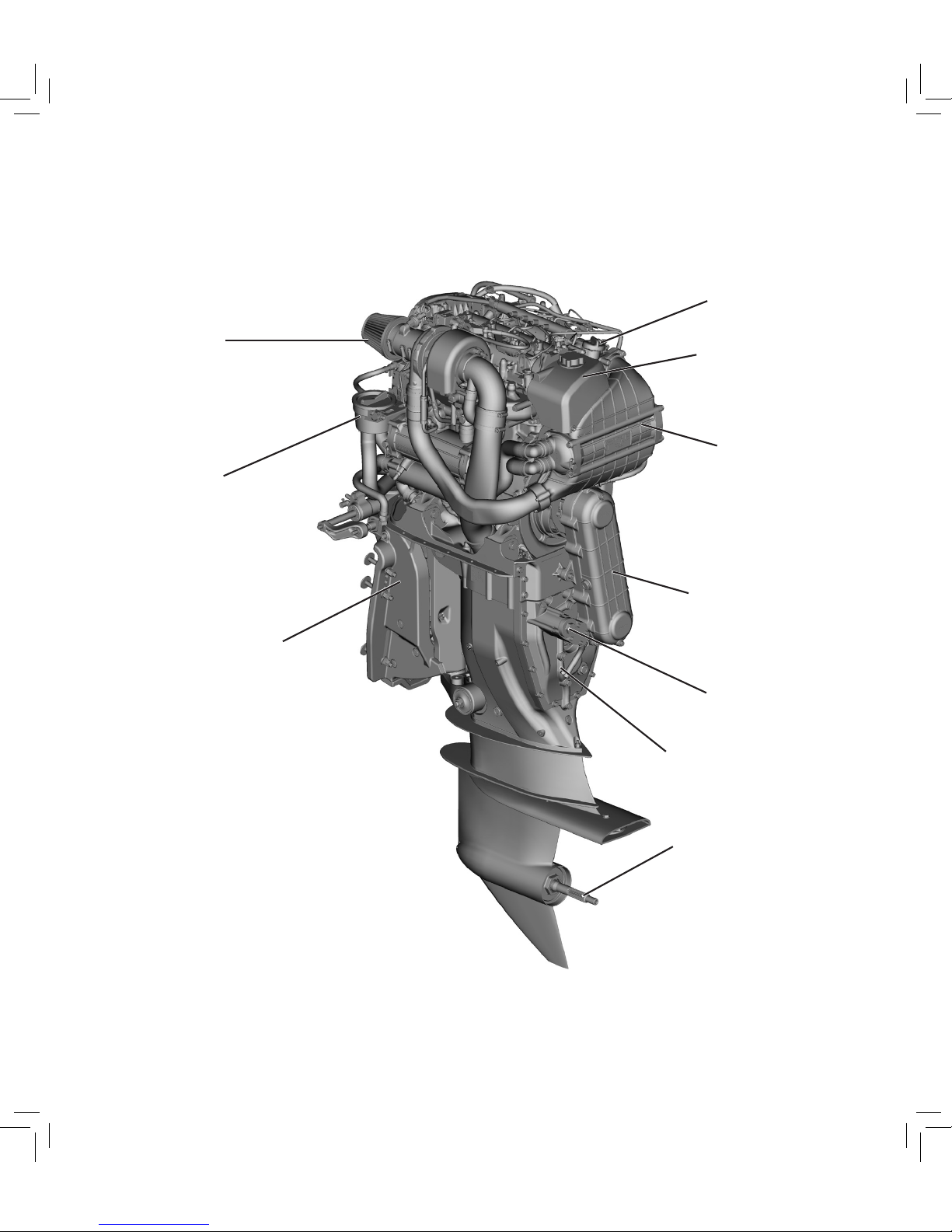
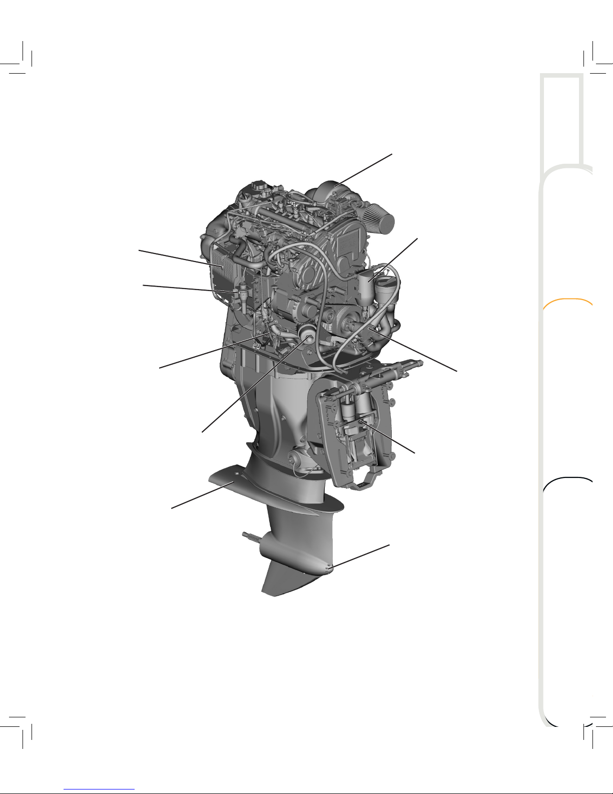
MAIN COMPONENTS
Engine oil filler cap
Expansion tank
Intercooler
Belt housing
Hydraulic pump
and filter
Transom
mount
Seawater
strainer
Air filter
Gearbox
Propeller
axis
Page 13
7
Transom mount
with tilt and trim
cylinders
Seawater pump
Engine
connector
Engine oil
dip stick
Engine
oil filter
Engine
control unit
(ECU)
Fuel filter
Turbo charger
Water intake
Anti cavitation plate
Technical data Maintenance
Operating Overview
Page 14
8
OVERVIEW
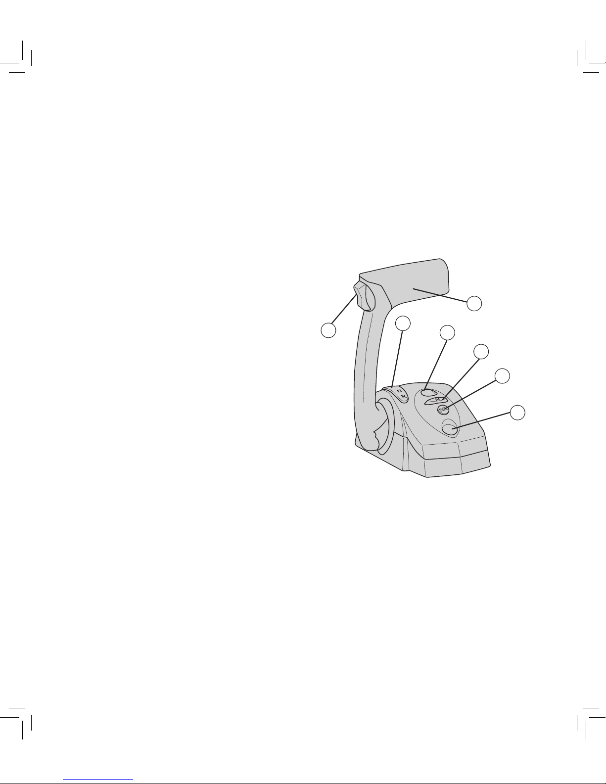
CONTROL HEAD
The control head engages both gear shiing and
acceleration. Depending on single installation
or multi installation of outboards, the boat is
equipped with a single or twin shi control
head. This description comprises a single shi
control head only. Also refer to Single Control
Head Manual or Twin Control Head Manual.
1. Engine trim control
2. Control lever
3. Lever position indicator
4. Control lamp
5. Neutral button
6. SEL button
7. Indicator lamp
INSTRUMENTATION
For instruments and gauges, refer to
corresponding Display manual.
1
3
6
7
4
2
5
Page 15
9
CONTROL HEAD OPERATION
!
WARNING
Be very cautious when first engaging the
gears to establish that FORWARD is truly
forward and REVERSE is truly reverse.
A quick in-and-out of the gear test is
recommended. Ensure that the boat is clear
of all obstacles around the boat before
conducting this test.
Control lamp
The control lamp (4) has a steady light
indicating that the control head is active.
!
WARNING
A fast flashing light indicates a non-critical
fault which may cause the boat speed to
be reduced. The system will continue to
operate.
Indicator dimming feature
When the control head is active, pressing the
SEL button (6) repeatedly will cycle through
the available indicator brightness levels.
Neutral indicator lamp
The neutral indicator lamp (7) has four states:
– Fast flashing in combination with lamp (4)
indicates a critical fault which may result in
limited or no system performance.
!
DANGER
Call for assistance, use another
controlling device, or use manual
override in an emergency.
– Steady light: engine is in neutral
– Slow flashing (0.5 s on, 0.5 s off): Neutral
Throttle Warmup is engaged.
– Very slow flashing (1 s on, 1 s off): Trolling
mode is engaged.
Technical data Maintenance
Operating Overview
Page 16
10
OVERVIEW
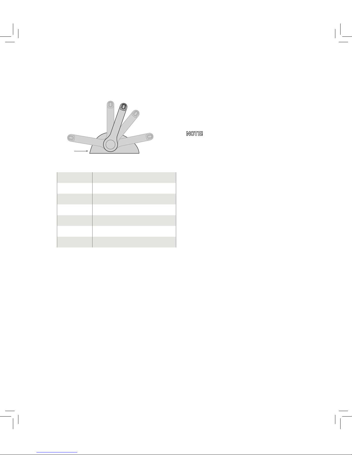
Control head range
Full speed forward
Adjusng
screws
Full speed reverse
Reverse idle
Neutral
Forward idle
Forward idle to 100% of max engine rpm
Reverse idle to 50% of max engine rpm
NTW idle to 50% of max engine rpm
TM forward idle to 20% of max engine speed
TM reverse idle to 20% of max engine rpm
LSC forward idle rpm
LSC reverse idle rpm
Neutral Throttle Warmup
Neutral Throttle Warmup (NTW) allows to
control the engine throttle without gear
engagement, in order to warm up the engine at
a higher rpm.
NOTE! Maximum rpm is limited to 2400 rpm.
A slow flashing neutral indicator lamp (7)
shows that NTW is engaged.
Engaging Neutral Throttle Warmup
Move the control lever (2) to the Neutral
position. The neutral indicator lamp (7) will
have a steady light.
Press the N button (5). The neutral indicator
lamp (7) flashes to indicate that NTW is
engaged.
It is now possible to increase throttle and the
engine will stay in neutral.
Disengaging Neutral Throttle Warmup
Return the lever (2) to the Neutral position.
Press the N button (5). The lamp (7) will have
a steady light. The engine and transmission will
now respond normally to lever commands.
Page 17

11
Low Speed Control
Normal propeller
rpm range:
idle to max rpm
LSC propeller rpm range:
0 to idle rpm
Low Speed Control (LSC) enables
unprecedented control while mooring and
low speed maneuvering. LSC incorporates
an electro-hydraulically operated clutch that
ensures smooth shiing between neutral,
forward and reverse.
The sensor controlled propeller speed allows
for seamless control from zero to maximum
rpm. The boat is fully operable even below
3-4 knots.
Trolling Mode
When engaging Trolling Mode (TM) the full
throttle range represents 20% of normal throttle
range. This enables a higher resolution of the
throttle maneuvering thus giving the operator a
more precise control in demanding situations.
A very slow flashing (one second on, one
second off) neutral indicator lamp (7) indicates
that TM is engaged.
Engaging Trolling Mode
Move the control lever (2) to forward idle or
reverse idle positions.
Press the N button (5). The lamp (7) will flash
slowly to indicate that TM is engaged.
Disengaging Trolling Mode
Move the control lever (2) to forward idle or
reverse idle position.
Press the N button (5). The flashing lamp (7)
will go out to indicate that TM is disengaged.
Technical data Maintenance
Operating Overview
Page 18
12
OVERVIEW
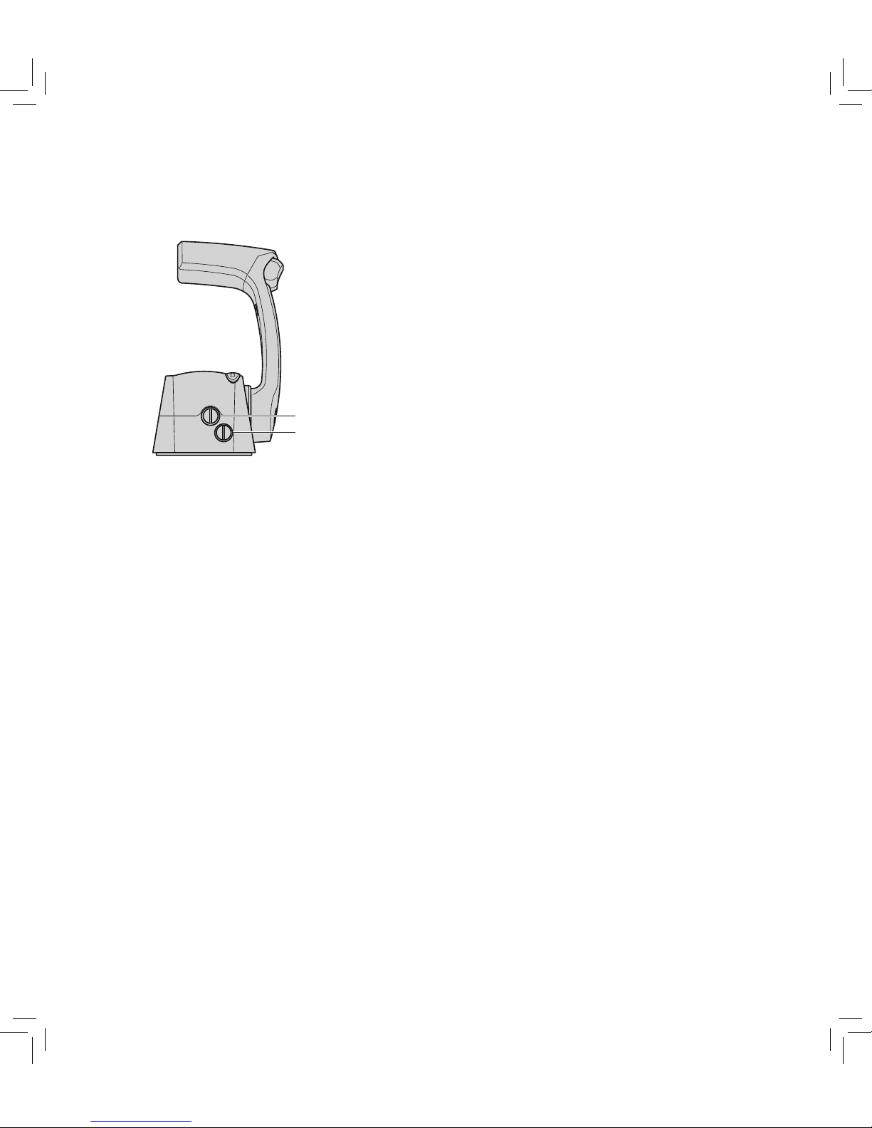
Adjustable lever feel
Throle fricon
Shi detent
The friction drag on the lever and the force
required to move in and out of the shi detents
can be set according to operator preference.
Turn the throttle friction screw clockwise to
increase the friction on the lever, counterclockwise to reduce the friction.
The shi detents are ment to prevent accidental
gear engagement. Bear that in mind when you
make adjustments. Turn the shi detent screw
clockwise to increase, counter-clockwise to
decrease force.
Page 19
13
OUTBOARD INSTALLATION
The information presented in this section is
intended as reference only. For more detailed
information, refer to Installation Manual.
Safe and proper mounting depends on
experience and the specific boat and outboard
combination. Therefore we strongly recommend
that your local dealer install the outboard and
related accessories to ensure proper installation
and good performance.
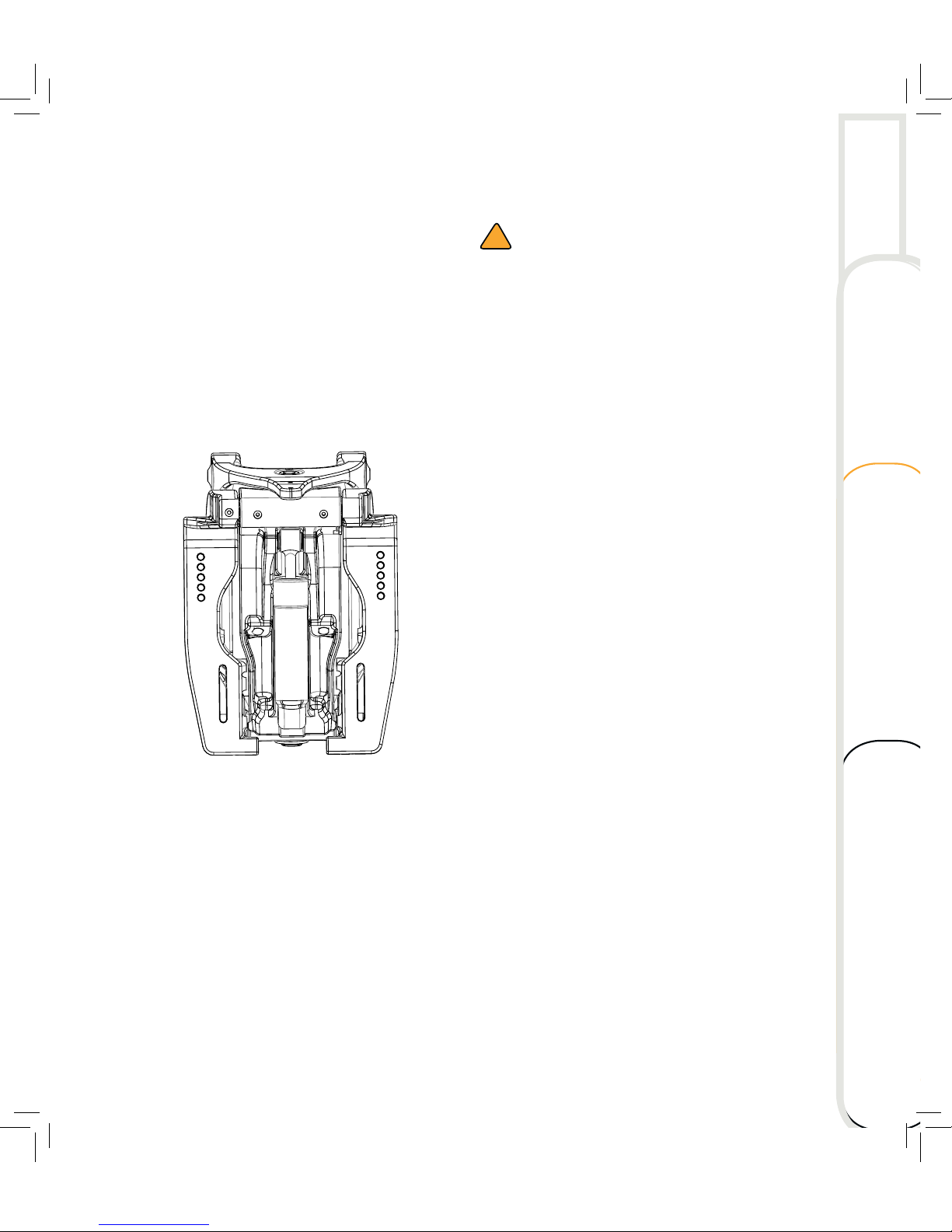
Bolt pattern
!
WARNING
Exceeding the boat’s maximum power
rating can cause serious injury or death.
Overpowering the boat can affect boat
control and flotation characteristics or break
the transom. Do not install an outboard that
exceeds the boat’s maximum power rating.
Improper mounting of the outboard can
result in hazardous conditions such as poor
handling or loss of control. Your dealer or
other person experienced in proper rigging
should mount the outboard.
Use mounting hardware to secure only the
outboard to the boat. Do not use outboard
mounting hardware to attach accessories.
Technical data Maintenance
Operating Overview
Page 20
14
OVERVIEW
MOUNTING THE OUTBOARD
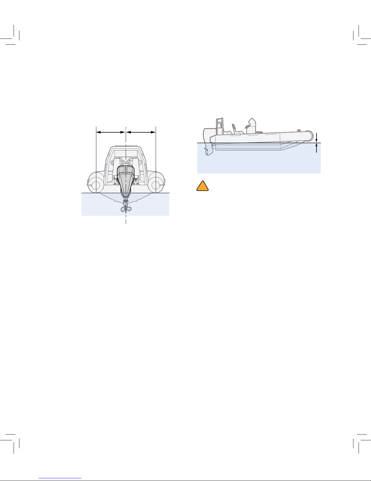
The outboard should be mounted in such a way
that the boat is well balanced. Otherwise it could
be difficult to steer. Mount the outboard on the
centerline (keel line) of the boat.
Mounting height
The mounting height of the outboard affects
its efficiency and reliability. A mounting that
is too high might lead to propeller ventilation,
which will reduce propulsion due to excessive
propeller slip. There is also a risk of overheating
the outboard due to the water intakes of the
cooling system may not get enough water
supply.
If the outboard mounting is too low, the water
resistance will increase and thereby reduce the
efficiency and performance of the outboard. In
general, the outboard should be mounted so
that the anti-cavitation plate is in alignment with
the bottom of the boat.
The optimum mounting height is determined
by the boat/outboard combination in addition
to the required use. Test runs at different
heights can be of assistance when choosing
the optimum mounting height. For further
information, please contact the manufacturer.
!
CAUTION
Check the carrying capacity of the boat, at
rest and with maximum load, during water
testing.
Check that the static water level on the
outboard rig is low enough to prevent water
from entering the powerhead when water
rising due to waves when the outboard is not
running.
Incorrect engine height can create air born
water spray while the boat is cruising. If the
outboard is operated continuously in the
presence of airborne water spray, enough
water could enter the engine throught the
intake opening on the cowling to cause
severe engine damage. Eliminate the cause
of airborne water spray.
Page 21
15
Engine connector
Connect the helm harness to the engine
harness. Refer to Installation Manual.
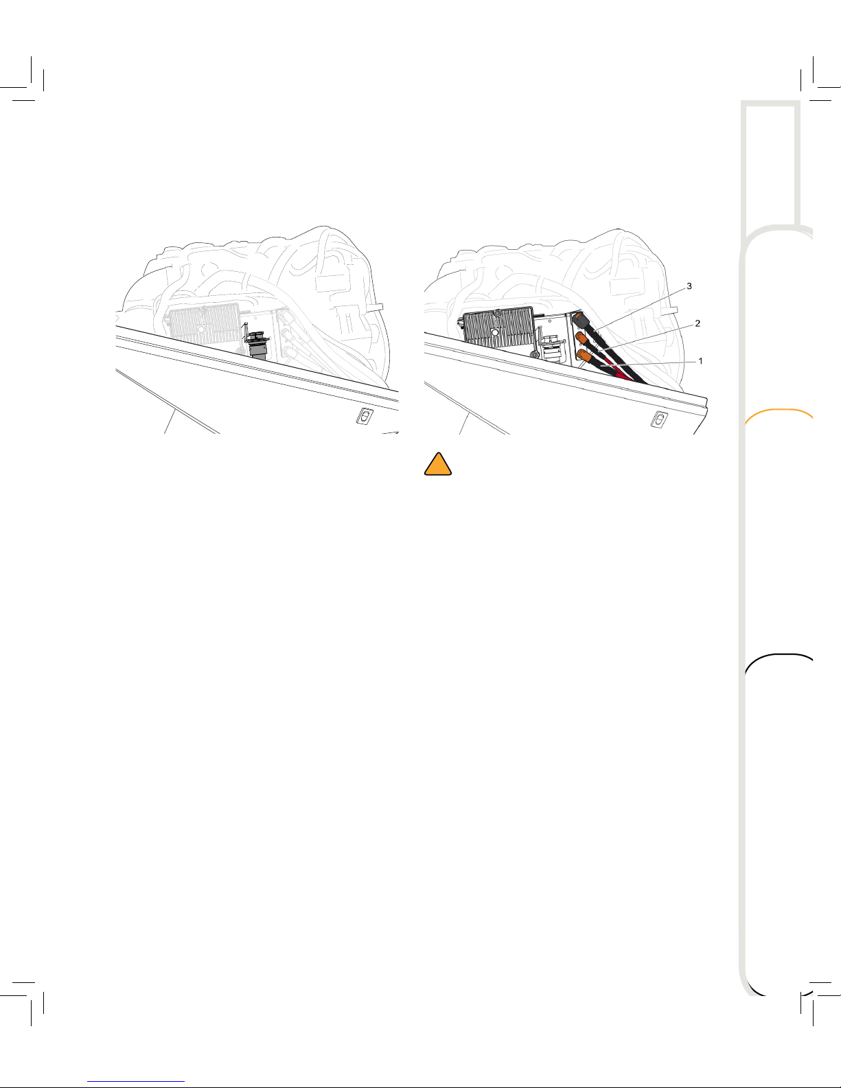
Connecting the battery
!
CAUTION
Make sure the main switch is OFF before
working on the battery connections.
1. Connect the largest cable, black, (black
connector) (1) to the upper end pin
connector. Make sure it ”clicks”!
2. Connect the smaller red cable (red
connector) (2) to the center pin connector.
Make sure it ”clicks”!
3. Connect the larger red cable (red
connector) (3) to the lower end pin
connector. Make sure it ”clicks”!
Also read the Installation Manual, section
Power cable Installation Process to learn
more details about connecting power to the
outboard.
Technical data Maintenance
Operating Overview
Page 22
16
OVERVIEW
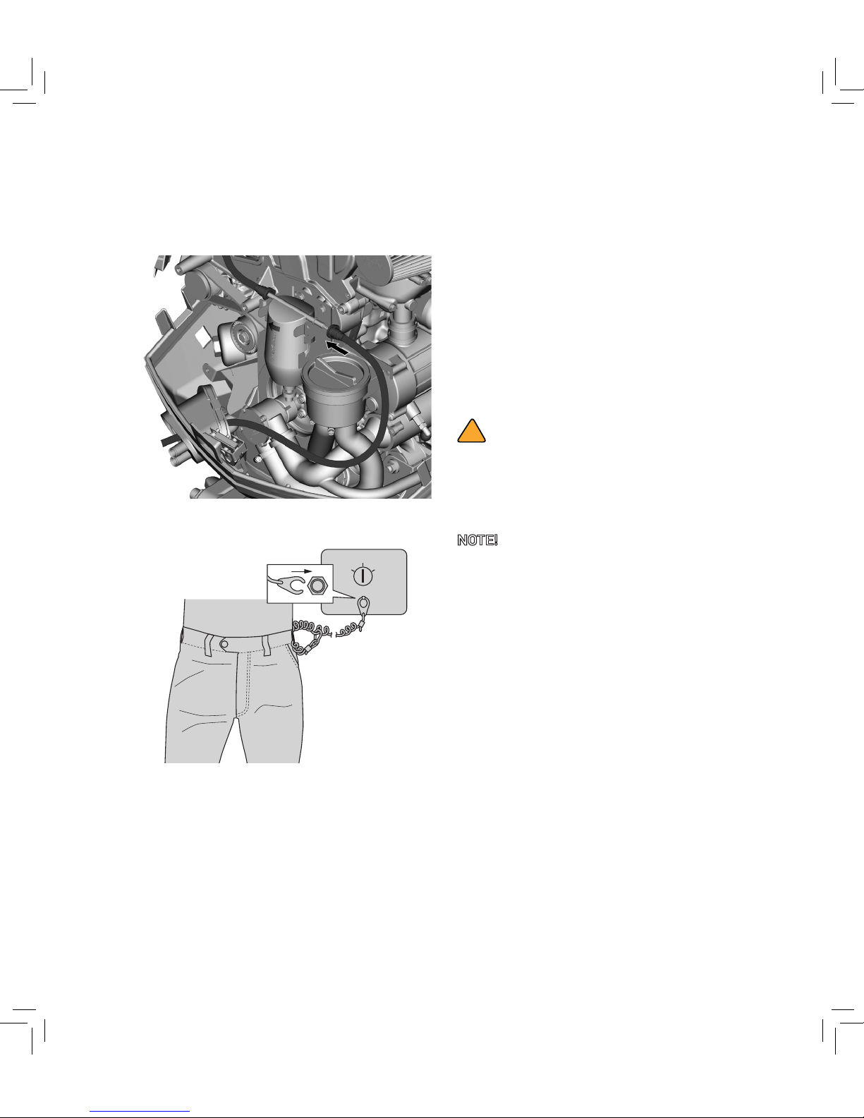
Connecting fuel line
Connect the fuel line to the fuel filter.
Engine shut-off cord
OFF START
ON
One clip must be attached to the engine
shut-off switch, the other to a secure place on
the operator’s floating device or wrist. If the
operator falls overboard or moves far enough
away from the operator’s position the engineshut-off cord will stop the engine, thereby
prevent the boat from running away under
power.
BREAKING IN THE ENGINE
The OXE Diesel outboard, as well as all new
engines, needs a period of breaking in. This is to
allow mating surfaces of moving parts to wear
in evenly. Correct break-in will help to ensure
proper performance and a prolonged engine
life. Most diesel engines notices an increase in
performance and reduction in fuel consumption
aer 150 hours of breaking in time.
!
CAUTION
Failure in following the break-in procedure
can result in severe engine damage or
reduced engine life.
NOTE! Run the outboard in water and in gear
with a propeller installed as follows.
1. First 2 hours of operation:
Run the outboard at various speed up to
3200 r/min. Full throttle for maximum 1
minute every 10th minute. Do not run the
engine at idle for long periods.
2. Remaining eight hours:
Run the outboard at any speed. Avoid full
throttle for more then 5 minutes.
3. Aer the first 10 hours:
Operate the outboard normally.
Page 23
17
OPERATING
BEFORE START-UP
!
WARNING
Risk of accidents! Items in the pre-operation
checks not working properly, should always
be inspected and repaired before operating
the outboard.
Checking the fuel level
– Check the fuel level. Fill up if necessary.
– Ensure that there are no fuel leaks or
fumes.
– Check the fuel line connections to ensure
they are tight.
– Check the water in the fuel filter. Drain off
the water if necessary.
Controls
– Check the throttle, shi, and steering
for proper operation before starting the
engine.
– The controls should work smoothly,
without binding or unusual free play.
– Look for loose or damaged connections.
– Check that the main cable and the
connector are in good condition.
– Check that the gear is in neutral.
Outboard
– Check the outboard and the outboard
mounting.
– Check for loose or damaged fasteners.
– Check the propeller blades for damage.
– Check that the battery cables and
connections are in good condition.
– Check fitting of the top cowling.
NOTE! Check the water surrounding the boat
for any outboard oil leakage!
Technical data Maintenance
Operating Overview
Page 24
18
OPERATING
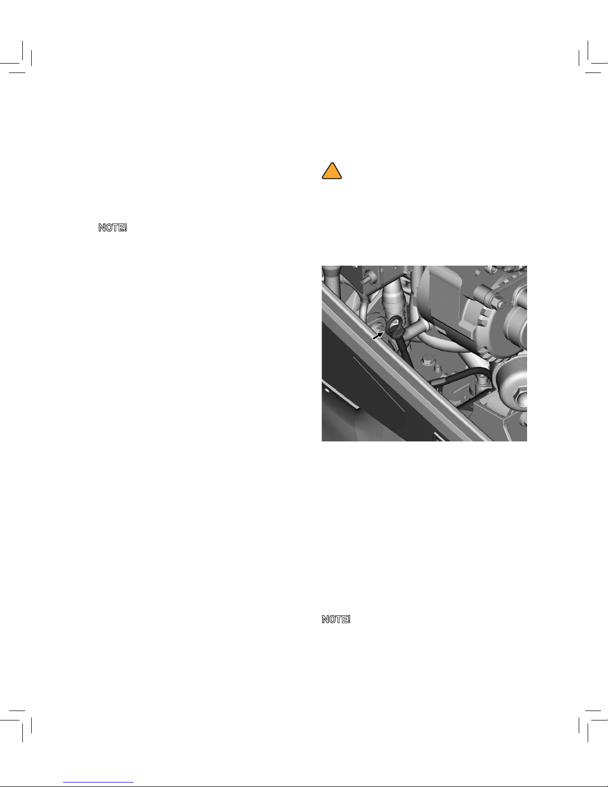
Check engine oil, hydraulic oil and belt oils
!
CAUTION
Ensure that the outboard is in vertical
position when checking engine oil level, gear
oil level and upper and lower belt oil level.
Check engine oil
1. Remove the engine oil dipstick and wipe
it clean.
2. Completely insert the dipstick and remove
it again.
3. Check that the engine oil level is between
the upper and the lower mark on the
dipstick. If below the lower mark, fill up
with engine oil. If oil level is above dipstick
upper mark drain appropriate amount
of oil. Excess oil level can cause reduced
performance and oil leakage.
NOTE! Be sure to completely insert the
dipstick into the dipstick guide.
4. Check for oil leaks.
Filling fuel
1. Remove the fuel tank cap.
2. Carefully fill the fuel tank with diesel.
3. Securely close the cap aer filling the
tank. Wipe up any spilled fuel.
NOTE! If necessary, refer to Priming the fuel
system.
Page 25
19
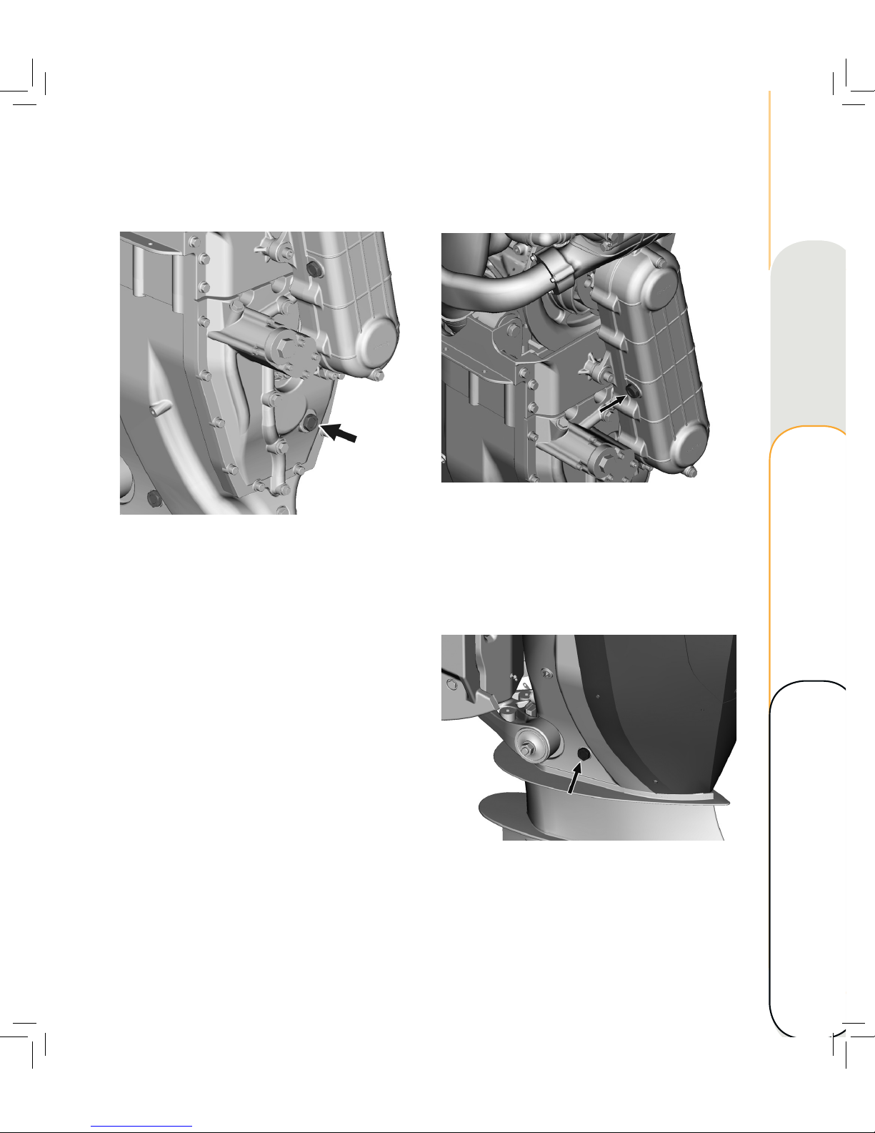
Check upper belt oil quality
1. Visually check oil quality: The oil colour
should be red to dark red.
If the oil looks milky and foamy, water has
entered the housing. Check for leakage
and replace the oil.
Check lower belt oil quality
1. Visually check oil quality: The oil colour
should be red to dark red.
If the oil looks milky and foamy, water
has entered the lower housing. Check for
leakage and replace the oil!
Check hydraulic oil
1. Visually check oil quality: The oil colour
should be red to dark red.
If the oil looks milky and foamy, water has
entered the housing. Check for leakage
and replace the oil.
2. Check that the oil is in level with the
sightglass.
3. Fill up if necessary.
Technical data Maintenance
Operating Overview
Page 26
20
OPERATING
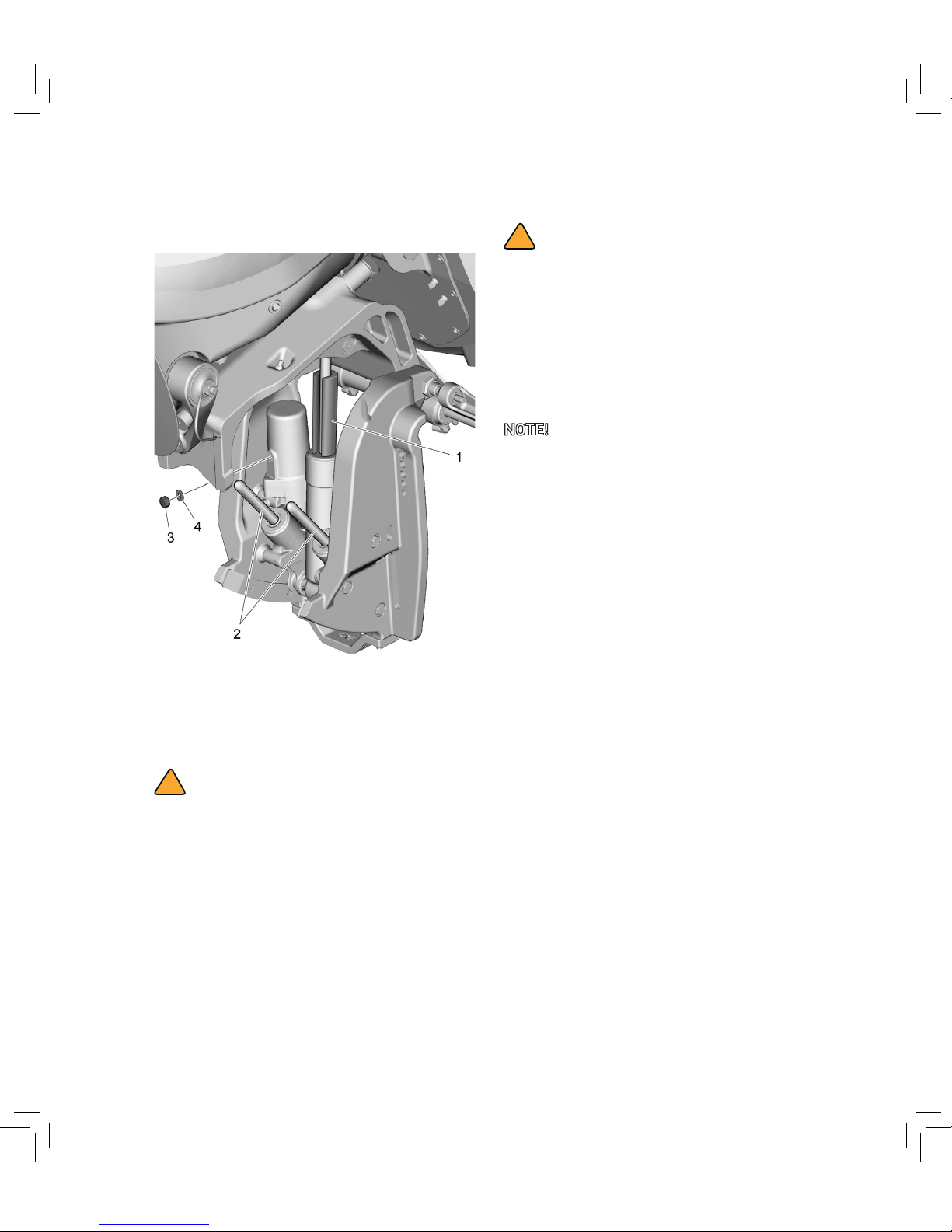
Check fluid level in power trim and tilt unit
1. Tilt up the outboard completely and
support the tilt cylinder with a transom
saver (1) .
!
WARNING
Make sure to support the outboard with the
transom tilt saver. Otherwise the outboard
can fall down accidentally if the power tilt
and trim unit looses pressure.
!
WARNING
Ensure that the trim and tilt rods (2) are
fully extended when the plug is removed.
Otherwise the fluid can spray from the
reservoir due to internal pressure.
2. Remove the filling plug (3) and seal (4).
Check the fluid level in the reservoir.
NOTE! If the fluid is correctly levelled, only a
small amount of fluid should come out of the
filling hole when the plug is removed.
3. If necessary, fill up with fluid of
recommended type until it comes out of
the filling hole.
Page 27
21
STARTING THE OUTBOARD
!
WARNING
Before starting the engine, make sure that
the boat is tightly moored and that you can
steer clear of any obstructions. Be sure that
there are no swimmers in the water near the
boat.
Prestart checks
– Check that the engine ignition switch stops
the engine.
– Confirm that removing the clip from the
engine shut-off switch stops the engine.
– Confirm that the engine cannot be started
with the clip removed from the engine
ignition switch.
OFF START
ON
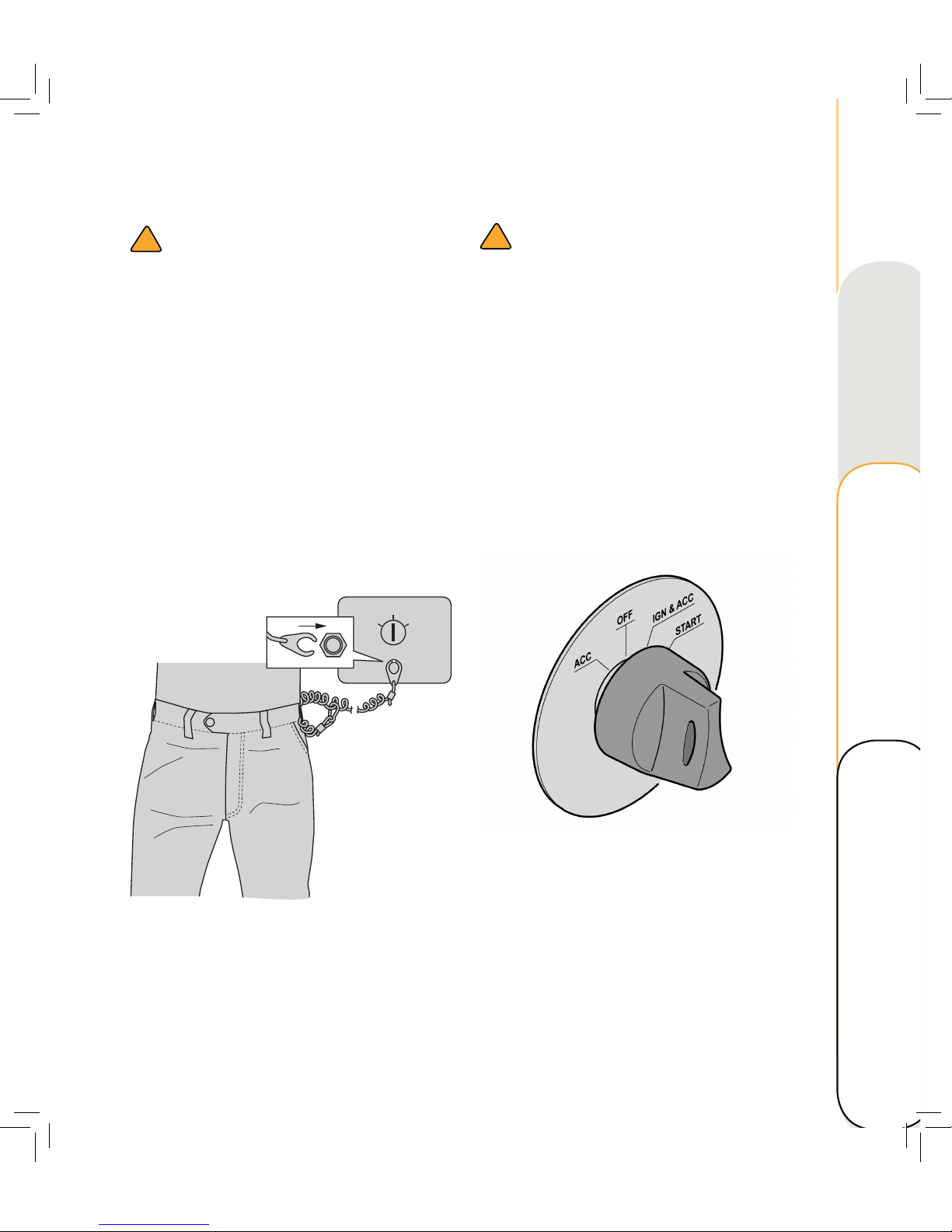
1. Attach the engine shut-off cord to your
floating device or your wrist. Then install
the other clip on the engine ignition
switch.
!
WARNING
Attach the engine shut-off cord in a secure
way to your clothes/floating device or wrist
while operating the boat.
Prevent the shut-off cord from entangling
with nearby objects and do not attach the
cord to clothing that could tear loose.
Avoid accidental or unintended activation
of the ignition switch. Unexpected loss
of forward motion can cause people and
obstacles beeing thrown forward. Loss of
power also leads to poor directional control.
2. Turn the ignition key to IGN & ACC.
3. Turn the key to START and hold it there
for a maximum of 5 seconds.
4. Immediately aer the engine starts,
release the key in order to return to the
IGN & ACC position.
Technical data Maintenance
Operating Overview
Page 28
22
OPERATING
!
CAUTION
Never turn the ignition key to start, while the
engine is running.
Do not let the starter turn for more than
5 seconds. If the starter is turned
continuously for more than 5 seconds, the
battery is discharged and the engine will not
start again. There is also a risk of damaging
the starter. If the engine will not start aer
5 seconds of cranking, return the key to ON
and wait for 10 seconds before cranking the
engine again.
Warming up the engine
5. Allow the engine to idle for 3 minutes
to warm up, otherwise there is a risk of
shortening the engines life.
6. Ensure that the oil-pressure warning does
not go on aer the engine has started.
7. Check for a steady flow of water from the
cooling water pilot hole.
!
WARNING
Stop the engine immediately if the oilpressure warning lamp flickers or is
constantly lit up and the buzzer sounds. Risk
for severe engine damage! Check the oil
level and fill up if necessary. If no cause for
the low oil pressure warning can be found,
contact your dealer or the manufacturer.
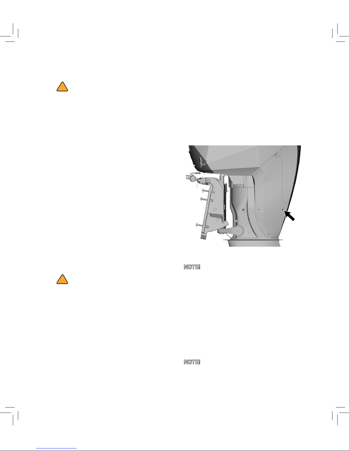
When the engine is running, a continuous
flow of water from the pilot hole shows
that the sea-water pump is pumping water
through the cooling passages. Stop the
engine immediately if no water is flowing
from the pilot hole. Risk for overheating or
serious damage to the engine!
Pilot hole
NOTE! It may take a while for water to start
flowing from the pilot hole if the water is frozen.
1. Check whether the sea-water inlet or
outlet is blocked. Clean if necessary.
2. Restart the engine.
If the fault still remains may indicate a
water pump failure or a blockage in the
cooling system.
3. Check the sea water pump impeller and
change if broken or worn. This may cause
the engine to overheat.
NOTE! If the impeller has dried out due to loss
of water in the water pump, the impeller has to
be replaced.
Page 29
23
!
WARNING
If the failure remains, have the outboard
checked by an authorized technician.
Operating the engine while overheated will
cause engine damage.
Shiing
!
WARNING
Before shiing, make sure that there are no
obstacles near the boat.
!
CAUTION
Warm up the engine before shiing gear.
Until the engine is warm, the speed might be
higher than normal.
N
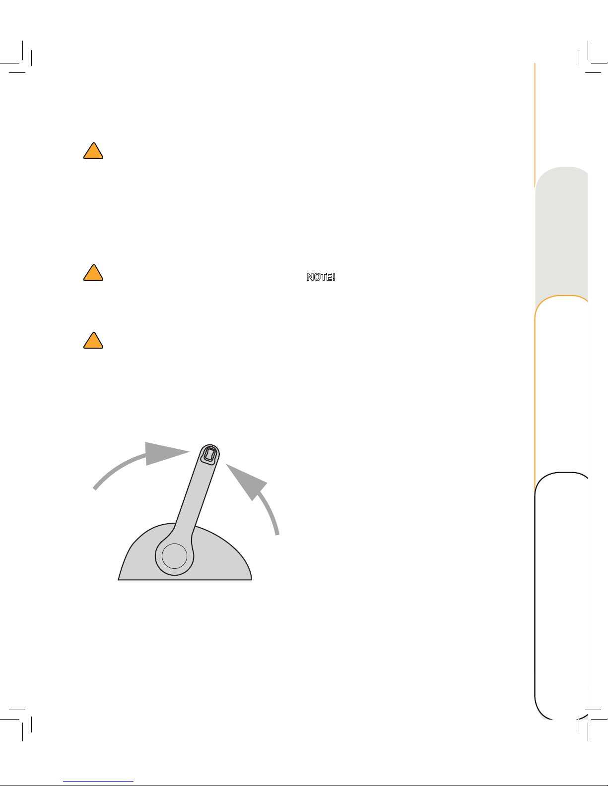
4. Place control lever in N (neutral) in order
to activate shiing and traction.
Refer to corresponding Control Head
Manual.
Stopping the engine
Let the engine cool off for a few minutes at
idle or low speed before stopping the engine.
Stopping the engine immediately aer operating
at high speed is not recommended.
1. Turn the key to OFF.
2. Remove the key if leaving the boat
unattended.
NOTE! The engine can also be stopped by
pulling the cord and removing the clip from the
engine shut-off switch, then turning the ignition
key to off-position.
Technical data Maintenance
Operating Overview
Page 30
24
OPERATING
POWER TRIM OPERATION
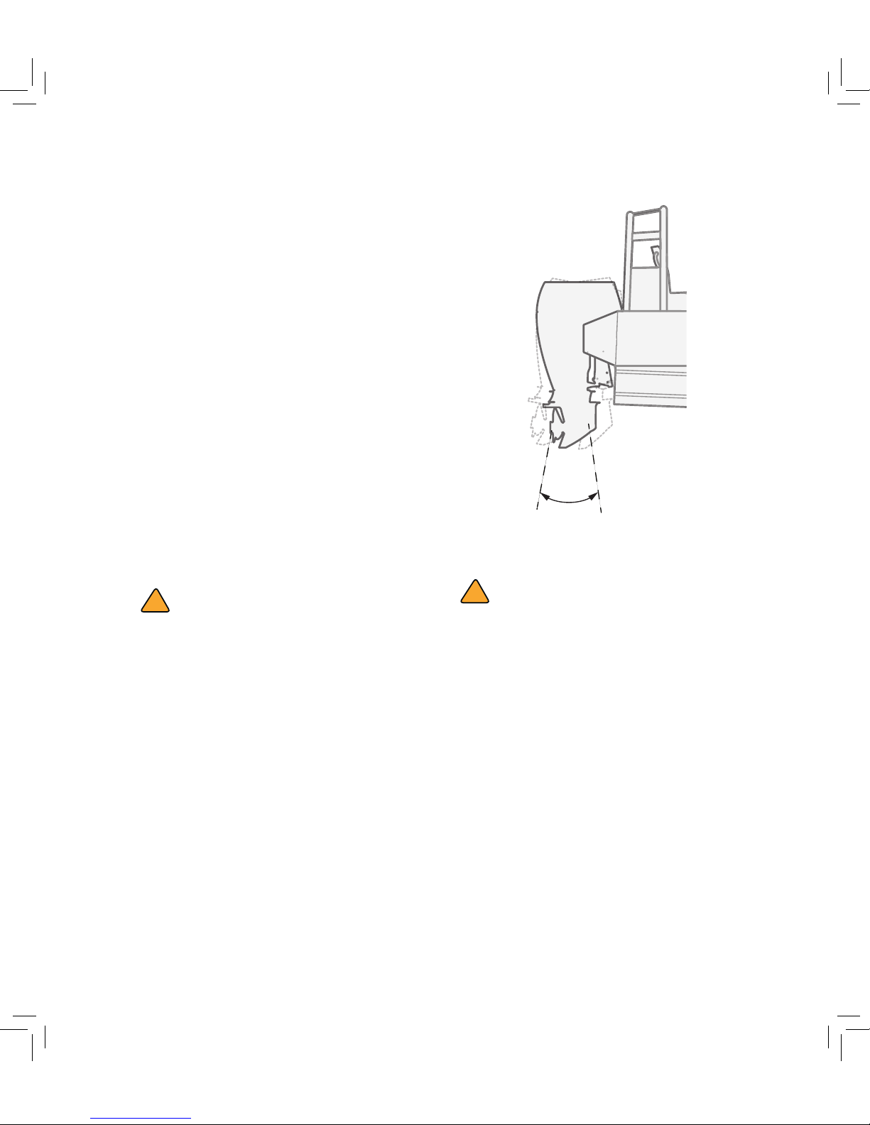
The OXE Diesel outboard is equipped with a
hydraulic trim system, with which you can
change the angle of the drive in relation to the
transom. The trim angle of the outboard is part
of the determination of the boat’s bow position.
A correct trim angle improves fuel economy and
reduce engine strain. The trim angle depends
on combination of boat, engine, and propeller.
The trim angle is also affected by other
variables such as the load in the boat, sea
conditions, and running speed.
With most boats, operating around the middle
of the trim range will give satisfactory results.
In order to take full advantage of the trimming
capability there maybe times when you choose
to trim the outboard all the way in (down) or out
(up).
!
DANGER
Avoid over-trimming (trim-up or trimdown) the drive system as this can affect the
steering of the boat severely.
Each boat has its own unique characteristics
and will be affected in different ways by the
factors involved, only general advice is given
here on how to get the best trimming angle
for your boat.
Get to know the power trim, make test
runs at slower speeds and at various trim
positions to see the effect of trimming. Note
the time it takes for the boat to plane, watch
the speed readings and the ride action of the
boat.
Trim operating angle
!
CAUTION
If the boat begins to feel unstable or is
harder to steer, slow down and /or readjust
the trim angle.
Page 31
25
Adjusting the trim angle
!
WARNING
Make sure that the boat’s occupants are
clear of the outboard when adjusting the trim
angle. Body parts can be crushed between
the outboard and the clamp bracket when
the motor is trimmed or tilted.
Adjust the outboard trim angle using the power
trim and tilt switch.
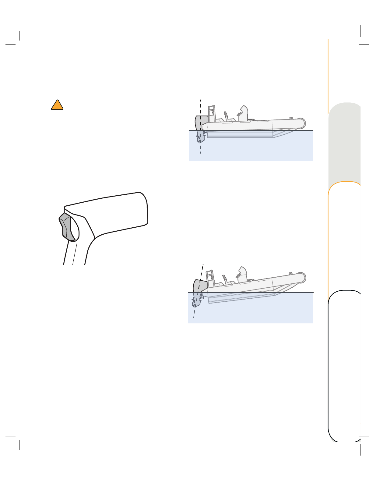
Power trim and tilt switch on single lever
– To raise the bow (trim-out), press the
switch UP (up).
– To lower the bow (trim-in, press the switch
DN (down).
Make test runs with the trim set in different
angles. When the boat feels well-balanced,
easy to steer and pleasant to operate, then the
optimal trim angle for the boat is achieved.
Adjusting the boat trim
A bow-up attitude results in less drag, greater
stability and efficiency when the boat is on
plane. With the bow up, the boat can have a
tendency to steer to one side or the other,
requiring compensational steering adjustments.
To help offset this effect, the trim tab can be
adjusted. It is easier to accelerate from a
standing start onto plane when the bow of the
boat is down.
Bow up
Too much trim-out or up can:
– Li the bow higher out of the water.
– Generally increase top speed.
– Increase clearance over submerged
objects or a shallow bottom.
– In excess, can cause boat porpoising
(bouncing) or propeller ventilation.
– Cause engine overheating if any cooling
water intake are above the waterline.
Technical data Maintenance
Operating Overview
Page 32
26
OPERATING
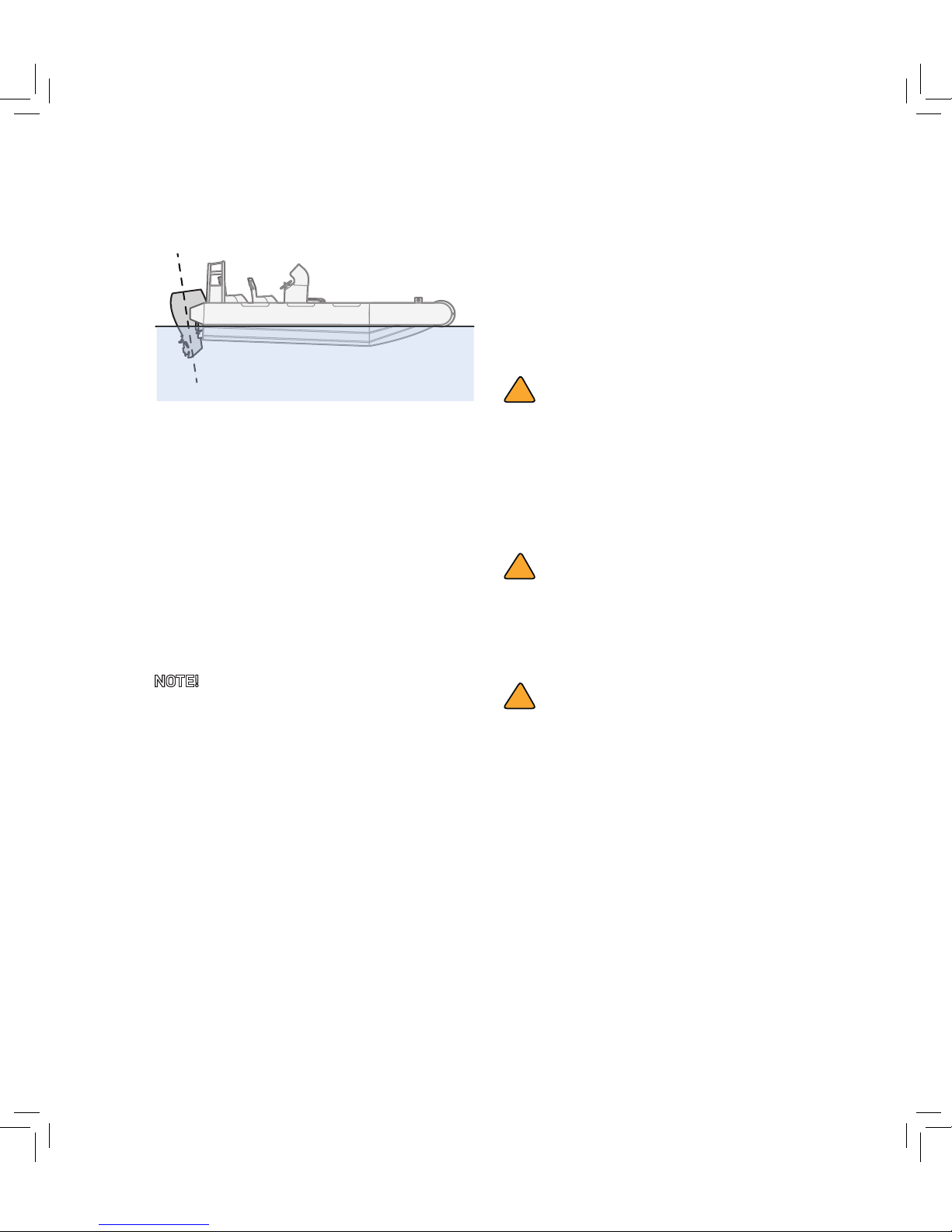
Bow down
Too much trim-in or down can:
– Lower the bow.
– Result in quicker planing off, especially
with a heavy load or a stern heavy boat.
– In excess, can lower the bow of some
boats to a point where they begin to plow
with their bow in the water while on plane.
This can result in an unexpected turn in
either direction (called bow steering or
oversteering) if any turn is attempted, or if
a significant wave is encountered.
NOTE! Depending on type of boat, the
outboard trim angle might have little effect on
the trim of the boat during operation.
POWER TILT OPERATION
If the outboard will be shut-off for a longer
period or if the boat is moored in shallow water,
the outboard should be tilted up. This is to
protect the propeller and lower housing from
damage by collision with obstructions, and also
to reduce salt corrosion.
!
WARNING
Make sure that the boat’s occupants are
clear of the outboard when adjusting the tilt
angle. Body parts can be crushed between
the outboard and the clamp bracket when
the outboard is trimmed or tilted.
!
CAUTION
Never tilt the outboard while the engine is
running. This could result in severe engine
and PTT-unit damage.
!
CAUTION
Make sure all the water intake holes stay
submerged at all times. Risk for severe
damage from overheating!
Page 33
27
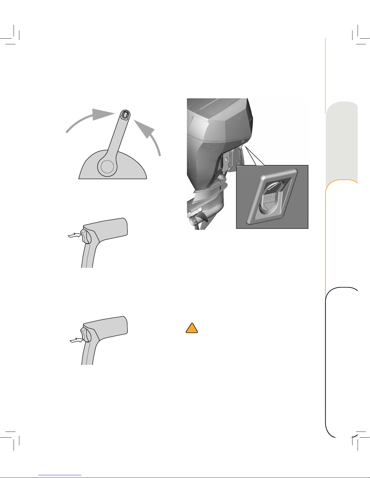
Procedure for tilting up
N
1. Place the control head lever in neutral
position.
2. Press the power trim and tilt switch UP
until the outboard has tilted up completely.
Procedure for tilting down
1. With the control head lever in neutral
position, press the power trim and tilt
switch DN to lower the outboard to the
desired position.
Power trim and tilt switch on engine cowling
Trim and tilt switch on cowling
The power trim and tilt switch is located on the
starboard side of the bottom engine cowling.
Pressing the switch up trims the outboard up to
a certain position and then tilts it up. Pressing
the button down tilts the outboard down and
trims it down. When the switch is released
the outboard will stop and stay in its current
position.
!
WARNING
Only use the power trim and tilt switch
located on the engine cowling when the boat
is at complete stop with the engine shut off.
Attempting to use the switch while the
boat is moving increase the risk of falling
overboard, distracting operator or collision
with other boats or obstacles.
Technical data Maintenance
Operating Overview
Page 34

28
OPERATING
Page 35

29
MAINTENANCE
OUTBOARD CARE
It is important that your outboard receive the
periodic inspections and maintenance listed in
the Maintenance Schedule, in order to keep
the outboard in best condition.
OWNERS RESPONSIBILITY
The owner is required to have routine engine
maintenance performed to maintain emission
levels within prescribed standards.
The owner is not to modify the engine in any
manner that would alter the power output
or allow emissions levels to exceed their
predetermined factory specifications.
TRANSPORTING THE
OUTBOARD
!
DANGER
Never get under the lowered outboard while
it’s tilted, even if a support bar is used.
Severe injury could occur if the outboard
accidently falls down.
When transporting the the boat on a trailer,
the outboard should be positioned in normal
running position. If the road clearance is
insufficient in this position, the outboard may
be transported in tilt position using a support
device such as a transom saver bar. Consult
your dealer for further details.
Additional clearance may be required for
railroad crossings, driveways and trailer
bouncing. Refer to your local dealer for
recommendations.
!
CAUTION
Do not rely on the power trim/tilt system
to maintain proper ground clearance for
transportation with a trailer. The power trim/
tilt system is not intended to support the
outboard under these conditions.
Technical data Maintenance
Operating Overview
Page 36
30
MAINTENANCE
STORING THE OUTBOARD
When storing your OXE Diesel outboard for
a longer period of time (2 months or more),
some important procedures must be performed
in order to prevent excessive damage. It is
advisable to have the outboard serviced by your
authorised dealer before storing.
!
CAUTION
To prevent oil from the sump entering
the cylinder, keep the outboard in upright
position when transporting and during
storage. Do not store or transport the
outboard on its side.
To prevent freezing damage, the seawater
system must be drained and the freshwater
system coolant must have sufficient
antifreeze protection, see Check coolant
level and mixture. Also refer to Service
Manual.
Store the outboard in a dry, well ventilated
place. Protect from sunlight.
Winterization of the outboard
When storing an engine for a prolonged period
of time or in sub-zero temperatures several
important procedures should be performed to
prevent engine issues.
For both short-term and long-term storage, see
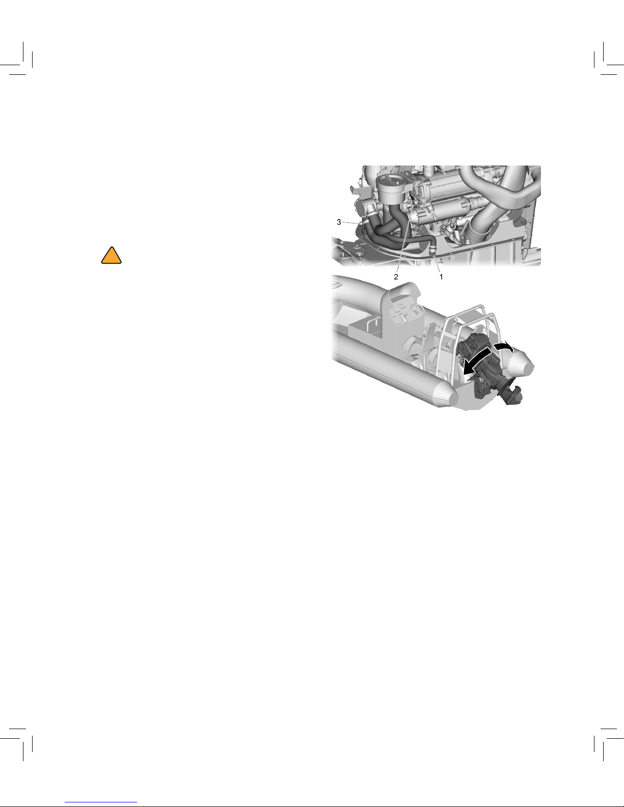
instruction below and picture
Short-term storage
1. Open connection (1).
2. Unscrew the plug on the side of the heat
exchanger (2).
3. Undo the hose on the seawater pump (3)
and drain the seawater
4. Tilt the outboard to a 45⁰ angle to drain as
much as possible of the seawater out of
the system.
5. When in this position, steer the outboard
fully to starboard and port. Repeat if
necessar y.
Page 37
31
CLEANING THE OUTBOARD
Aer operating in demanding conditions, flush
the cooling seawater passages with fresh water
to prevent them from becoming corroded or
blocked.
We also strongly recommend to increase
cleaning intervals of seawater strainer and
water intake when operating in muddy or turbid
water.
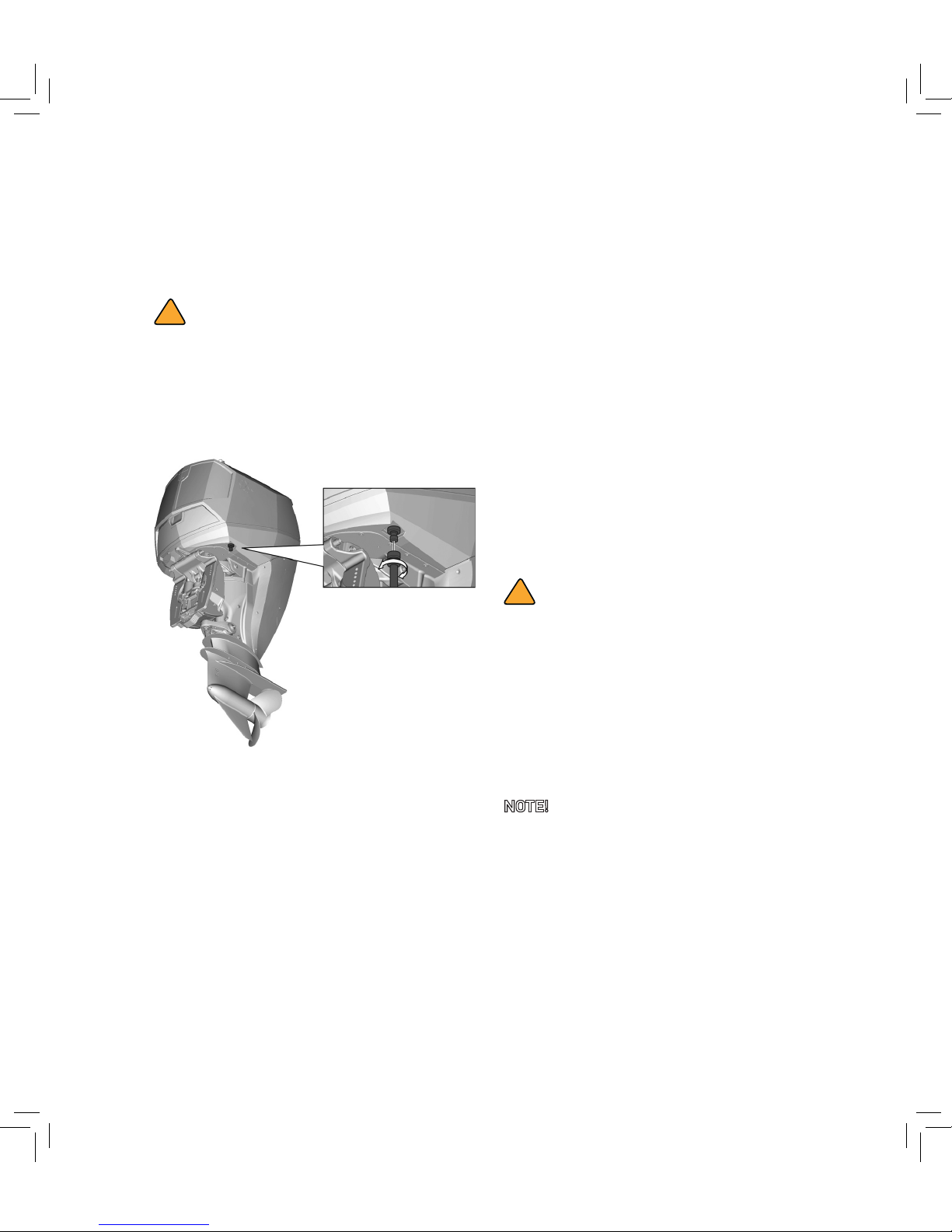
1. Rinse the outside of the outboard with
fresh water and, if possible, rinse the
power head under the cowling.
2. Drain the cooling seawater completely out
of the engine. Clean the body thoroughly.
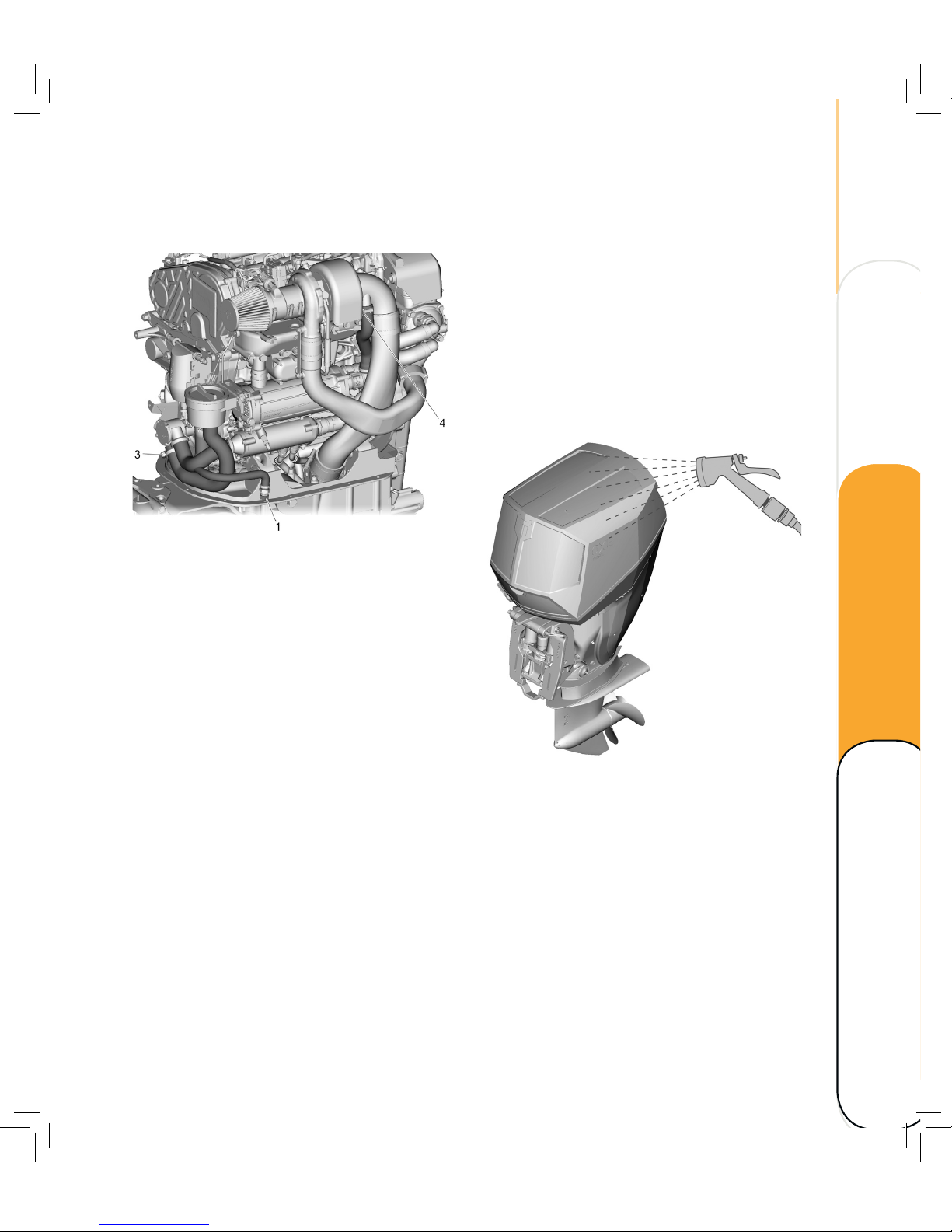
Long-term storage
1. Open connection (1) and place a container
beneath
2. Open the lower connection for the
seawater on the belt housing and place a
container beneath.
3. Open connection (4) and fill with coolant
fluid of sufficient grade temperature-wise
until it exits from connection (1) .
4. Undo the hose on the seawater pump (3)
and drain the seawater.
Alternative solution, long-term storage
1. Run the outboard with the water-intake
point in the front of the lower housing
lowered into a coolant fluid mixture of
sufficient grade.
2. Run the outboard until the entire sea-
water part of the system is filled with
coolant fluid and thus protected from
freezing and corrosion.
Technical data Maintenance
Operating Overview
Page 38
32
MAINTENANCE
FLUSHING THE POWER UNIT
Perform this procedure right aer operation to
achieve the best result.
!
WARNING
Do not perform this procedure while the
engine is running. The water pump may
be damaged and severe damage from
overheating can result.
Bottom cowling water fitting
1. Aer shutting down the engine, unscrew
the cap from the fitting on the bottom
cowling.
2. Screw a garden hose adapter onto a
garden hose, which is connected to a
fresh water supply. Then connect it to the
fitting on the bottom cowling.
3. With the engine off, turn on the water
flush through the cooling passages for
about 15 minutes. Turn off the water and
disconnect the garden hose adapter from
the garden hose connector.
4. Remove the adapter from the fitting on
the bottom cowling. Replace the cap and
tighten securely.
!
WARNING
Do not leave the garden hose connector on
the bottom cowling fitting or let the hose
hang free during normal operation. Water
will leak out of the connector instead of
cooling the engine, which can cause serious
overheating. Replace the cap aer flushing
the engine.
NOTE! When flushing the engine with the
boat in the water, tilting the outboard until it is
completely out of the water will achieve better
results.
Page 39
33
CHECKING AND OTHER MAINTENANCE
Check the battery
– Remove corrosion from the battery
connections and check that the cable
connections are tightened.
– Lubricate the battery terminals with
grease.
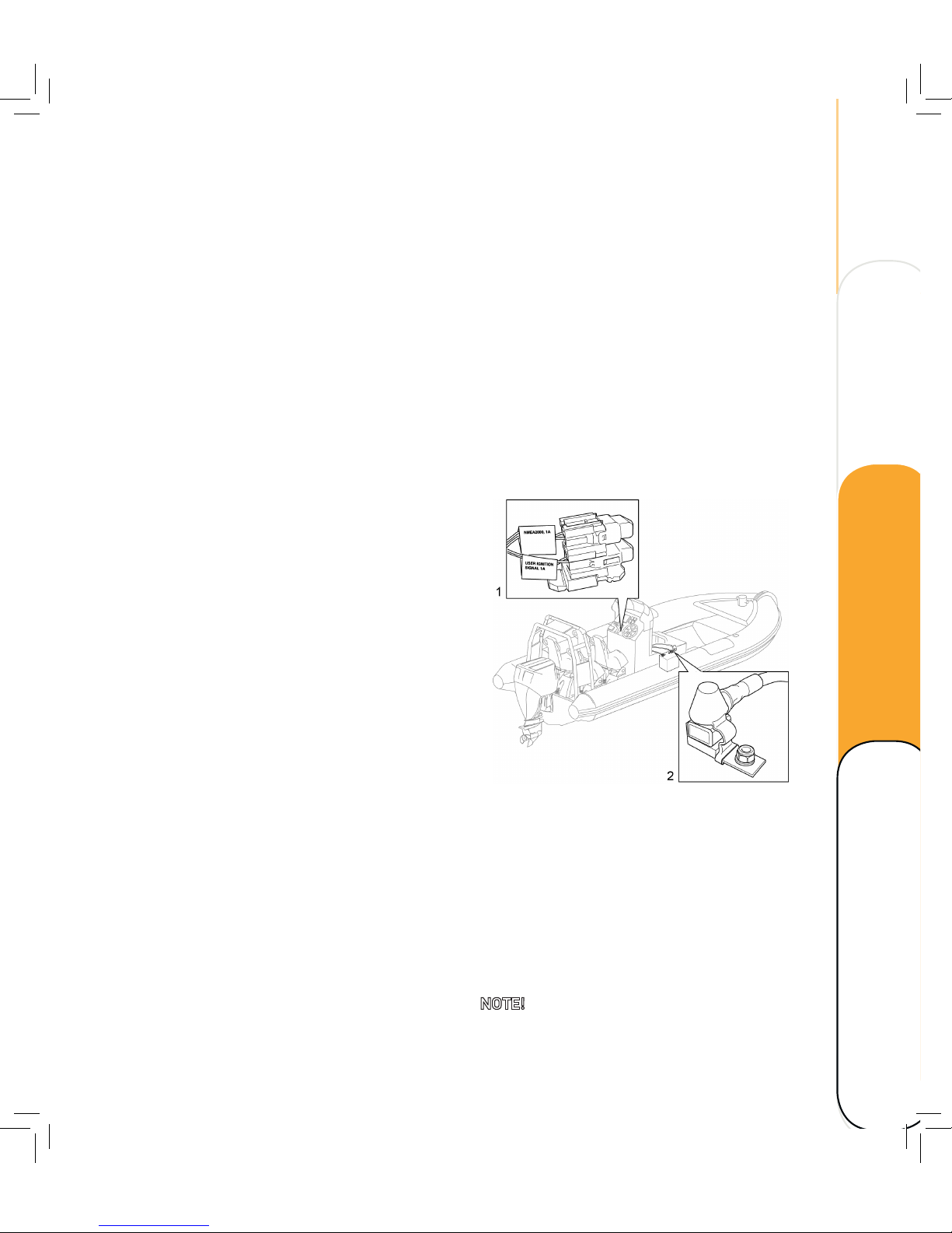
Check the electric system
– Check connections on the outboard.
– Remove corrosion from access points,
contacts and fuses. Lubricate with grease.
– Check fuses. Ensure spare fuses aboard.
1. a) NMEA2000, ATO 1A fuse, used only
in single engine application. In multi-
engine applications fused external supply
must be used to the NMEA2000 bus (3A).
b) User ignition signal, ATO 1A, used
only for ignition control of peripheral
equipment externally powered.
2. Use a 100 A fuse on the power supply,
control (thinner red cable).
NOTE! No fuse on the common power supply.
Check the intake system
It is of utmost importance for the intake system
to be intact. Broken and leaking pipes can
drastically shorten the life of the engine.
Check the system regularly.
– Check hoses for fissures and damage.
Replace, if necessary.
– Ensure that all hose clips and clamps are
tightened and fit easily.
– Check the air filter
– Check the filter insert for holes or cracks.
– Check for dampness.
– If damaged or otherwise blocked, replace
the air filter.
Check the air filter
– Check, replace if necessary, tubes and
hoses if leaking due to corrosion.
– Check joints and clamps.
– Check exhaust manifold.
– Start the outboard and check for exhaust
leaks.
Check the engine for oil leakage
– Check seals and gaskets.
– Check engine oil filter
Check drive belts
– Check alternator drive belt for wear or
damage.
– Check function of alternator drive belt
tension.
Technical data Maintenance
Operating Overview
Page 40
34
MAINTENANCE
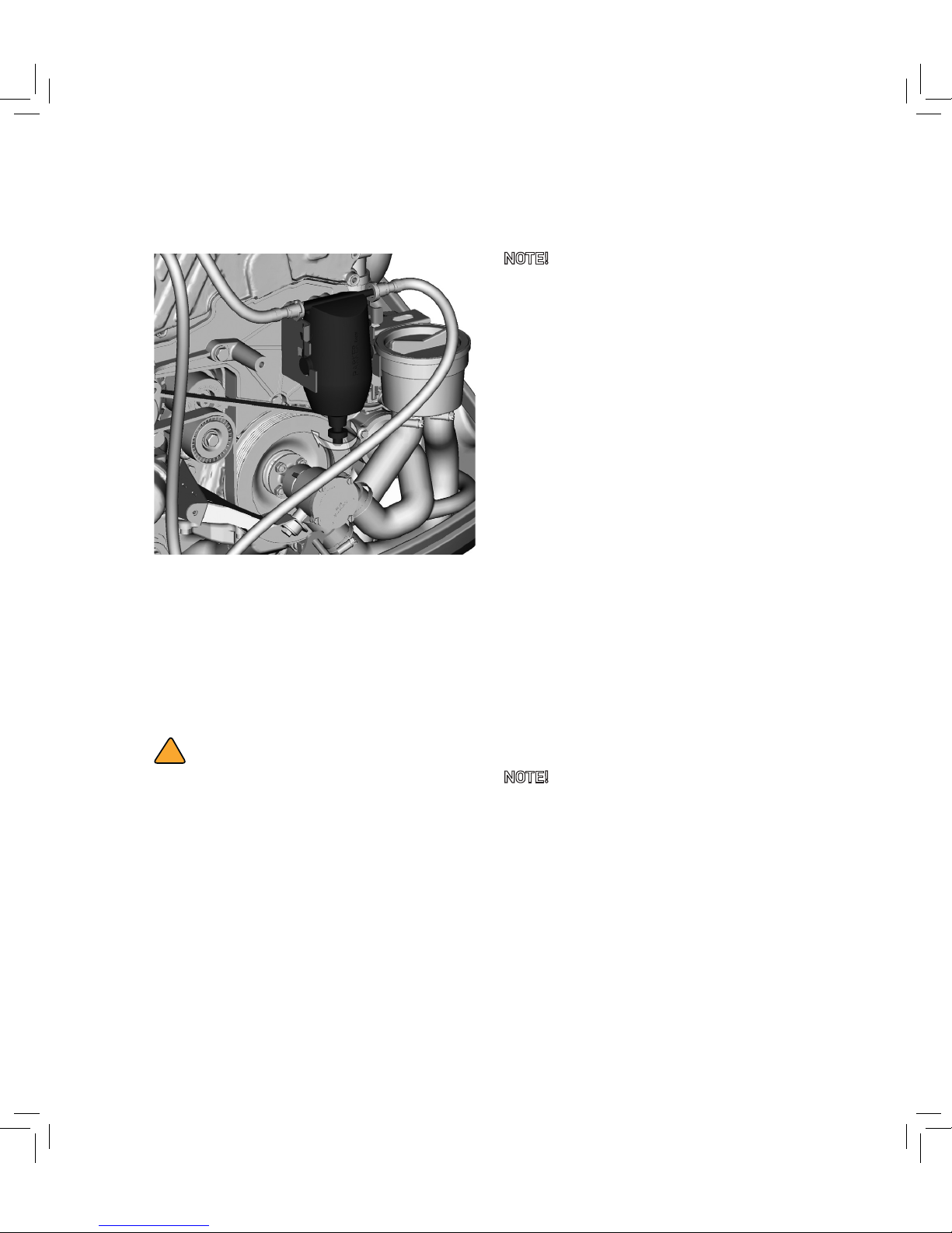
Check the fuel system
Fuel filter and water separator
– Check the fuel filter water separator. Drain
if necessary.
– Prime the fuel system and check hoses
and connectors for leakage.
!
WARNING
Turn off the engine immediately in case of
leakage.
Priming the fuel system
NOTE! In order for the diesel fuel system to
work properly, the fuel lines must be full of fuel
and contain no air. If air gets into the fuel lines,
it will be necessary to prime the fuel system
to eliminate the air before operating the boat.
Air could have entered the system in any of the
following ways:
– The boat ran out of fuel.
– The fuel lines have leaking joints.
– The filter was removed for service or
replacement.
– The fuel lines were removed or
disconnected for servicing.
– The fuel pump was removed for servicing.
– The fuel filter water drain cock was opened
while the engine was running.
If one or more of the above occurred, air has
entered the fuel system and you will need to
prime the system prior to operating the vehicle.
1. Turn the ignition key IGN&ACC. The fuel
pump will run for 20 seconds.
NOTE! Do not turn the ignition key to START.
This could damage the injection pump.
2. Repeat two or three times.
Page 41
35
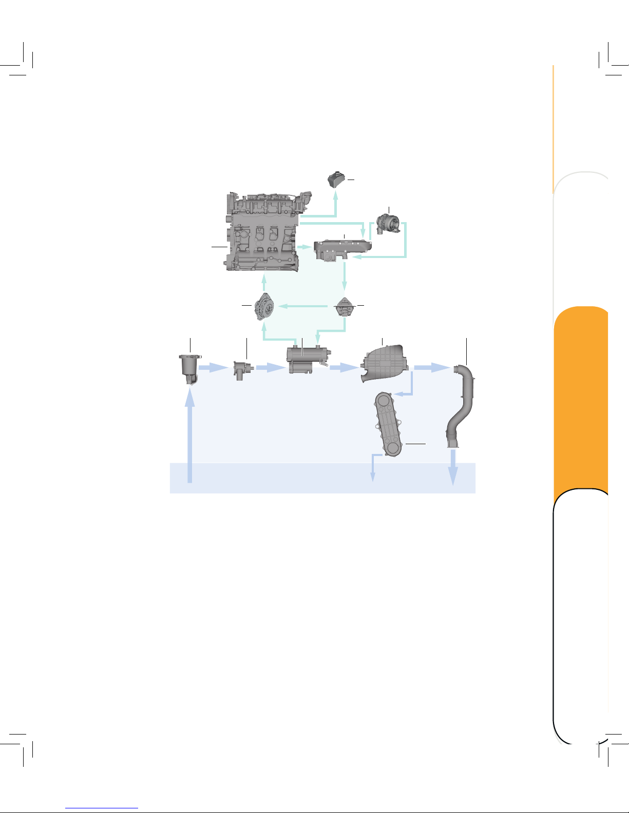
Check cooling system
1. Seawater strainer
2. Seawater pump
3. Heat exchanger
4. Intercooler
5. Exhaust pipe
6. Transmission cooler
7. Engine water pump
8. Engine
9. Exhaust manifold
10. Thermostat
11. Expansion tank
12. Turbocharger
Check the system regularly:
– Check hoses for fissures and damage.
Replace, if necessary.
– Check hose clips and clamps. Replace, if
damaged.
– Check that the water intake is not blocked.
Clean if necessary.
– Check the sea water strainer. Clean if
necessary.
– Check coolant level and mixture. Fill up if
necessary.
1 2 3 4 5
6
11
107
9
12
8
Technical data Maintenance
Operating Overview
Page 42
36
MAINTENANCE
Check water intake
Water intake
Make sure that the sea water intakes are not
clogged by seaweed or obstacles. Clean if
necessary.
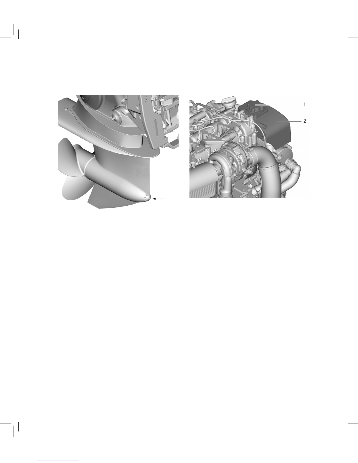
Check coolant level and mixture
Expansion tank
1. Check the cooling level, 4 cm below the
fillerneck edge. (2).
The cooling system of the engine is to be filled
with a mixture of distilled water and antifreeze
based on ethylene glycol and/or anticorrosion
additive, see Recommended fluids and grease.
Coolant must be added at the filler cap (1)
only.
Do not add cold coolant to a warm engine.
Ensure that the mixing ratio “water-antifreeze”
is preserved.
Page 43
37
Check power trim and tilt system
!
WARNING
Never get under the lower unit while it is
tilted. Risk for severe injury if the outboard
accidentaly falls!
Make sure no person is under the outboard
before performing this test. Risk of body
parts to be crushed between outboard
and clamp bracket when the outboard is
trimmed or tilted.
1. Check the power trim and tilt unit for any
signs of oil leaks.
2. Operate each of the power trim and tilt
switches on the remote control and lower
cowling to check that all switches work.
NOTE! The ignition key must be in IGN&ACC
position.
3. Tilt up the outboard and check that
the tilt rod and trim rods are extended
completely.
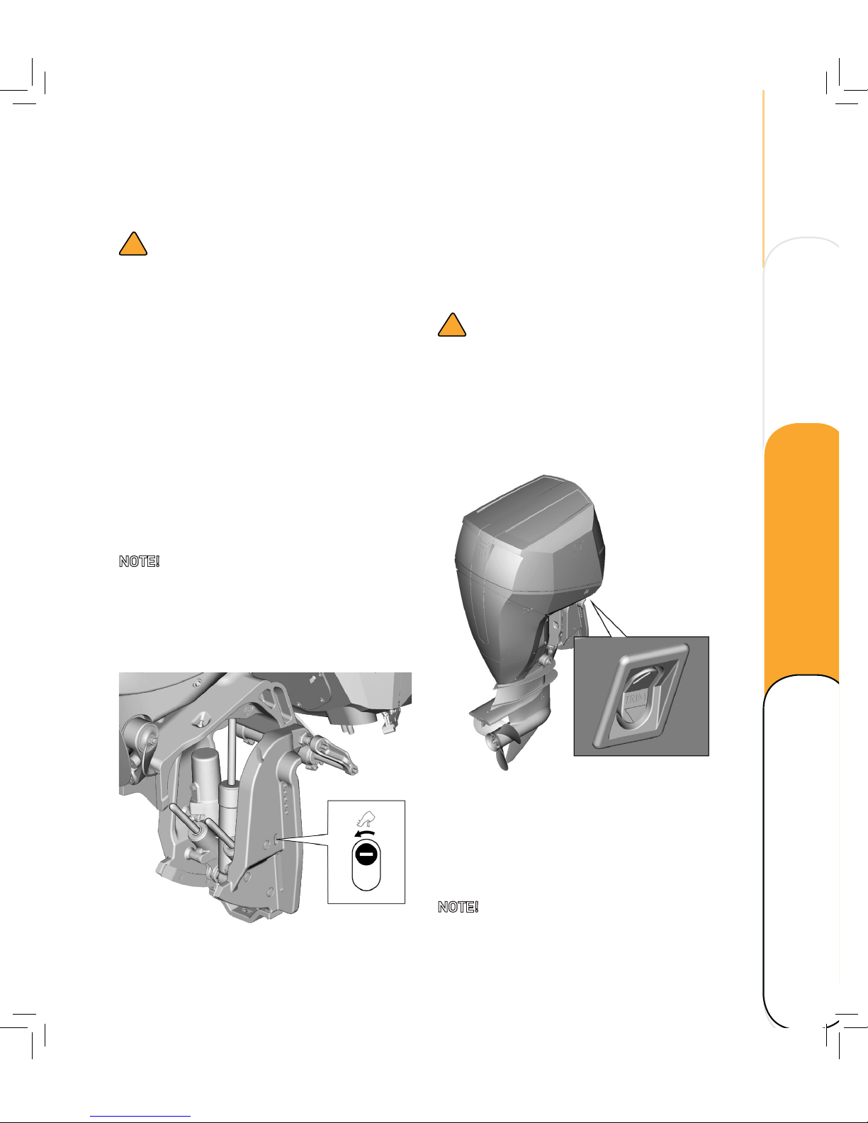
Tilt and trim rods, manual valve
4. Check that the tilt rod and trim rods are
free from corrosion or other flaws.
5. Activate the tilt-down switch until the
rods have retracted completely into the
cylinders.
!
CAUTION!
The outboard can belowered by carefully
turning manual valve, should the electric
system fail.
Ensure that the manual valve is tightened
before starting the outboard.
Tilt and trim switch on cowling
6. Activate the trim-up switch until the tilt
rod is fully extended.
7. Tilt the outboard down. Check that the tilt
rod and trim rods operate smoothly.
NOTE! Consult your dealer if any operation is
abnormal.
Technical data Maintenance
Operating Overview
Page 44
38
MAINTENANCE
Check the propeller
!
WARNING
You could be seriously injured if the engine
accidentally starts when you are near the
propeller. Before inspecting, removing, or
installing the propeller, place the shi control
in neutral, turn the key to OFF and remove
the key. Remove the clip from the engine
shut-off switch. Disconnect the battery main
switch.
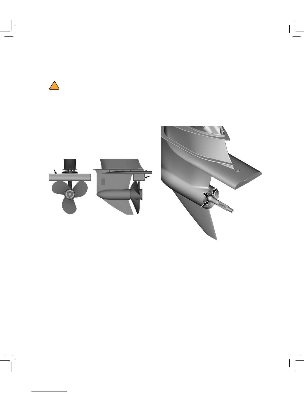
Loosen or tighten the propeller nut
Do not use your hand to hold the propeller
when loosening or tightening the propeller
nut. Put a wood block between the anticavitation plate and the propeller to prevent
the propeller from turning.
Propeller checkpoints
– Check each of the propeller blades for
erosion or other damage.
– Check the propeller sha for damage.
– Check the splines for wear or damage.
– Check for obstacles tangled around the
propeller sha.
Propeller sha oil seals
– Check the propeller sha oil seals for
leakage. Replace if necessary.
Page 45
39
Check painted surfaces
Check the outboard for scratches, nicks,
or flaking paint. Areas with damaged paint
surfaces are more likely to corrode. Clean and
paint the areas if necessary. Touch-up color is
available at your local dealer’s.
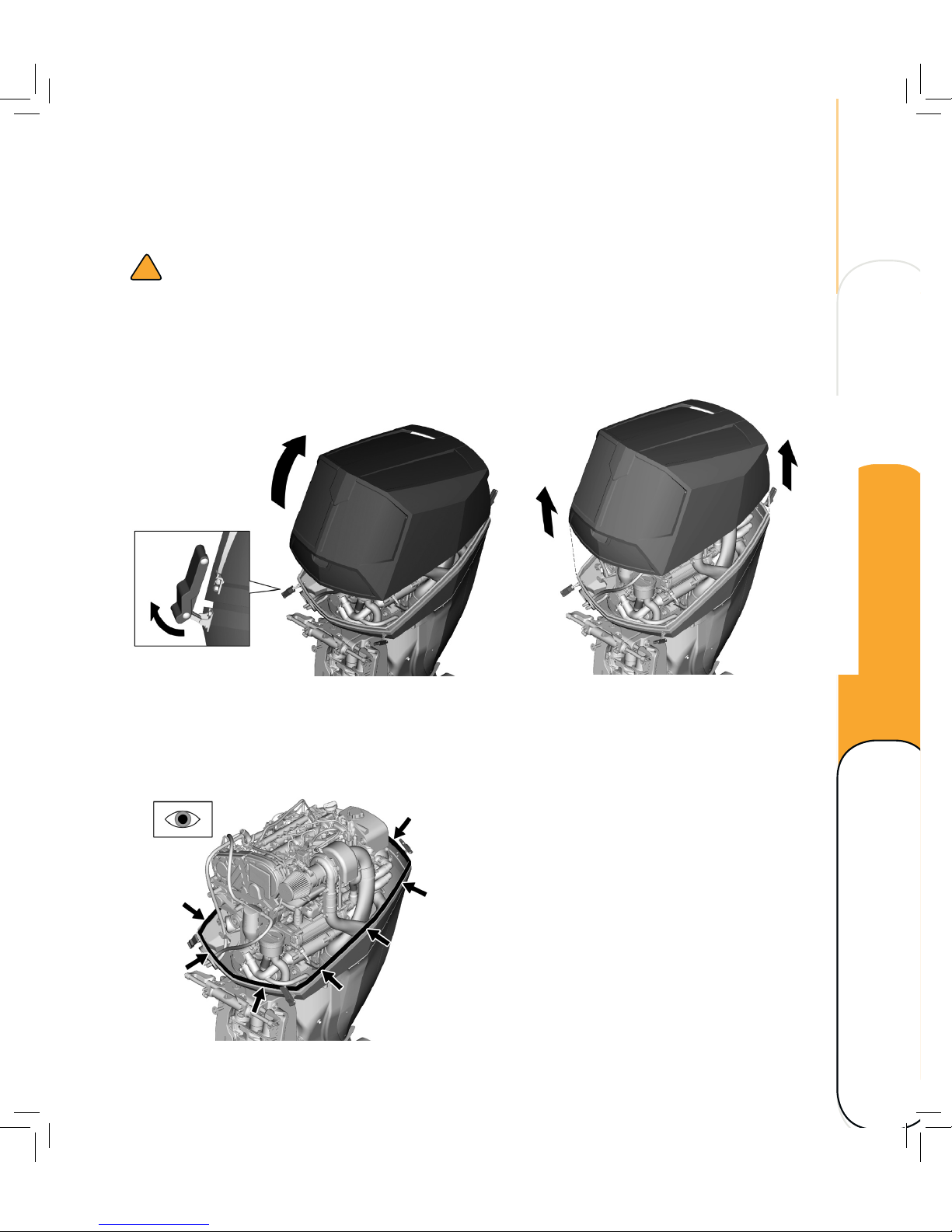
Check the cowling sealing
Check that the sealing is not dry, broken or
worn, as this will allow water to enter the
engine.
Check the top cowling
!
CAUTION
Make sure that the top cowling is securely
closed and that there are no gaps. A loose or
improperly fitted cover could allow water to
enter the engine.
Check the fitting of the top cowling. Reinstall
if the fit is not complete. Contact your dealer/
manufacturer if it is still loose.
Technical data Maintenance
Operating Overview
Page 46
40
MAINTENANCE
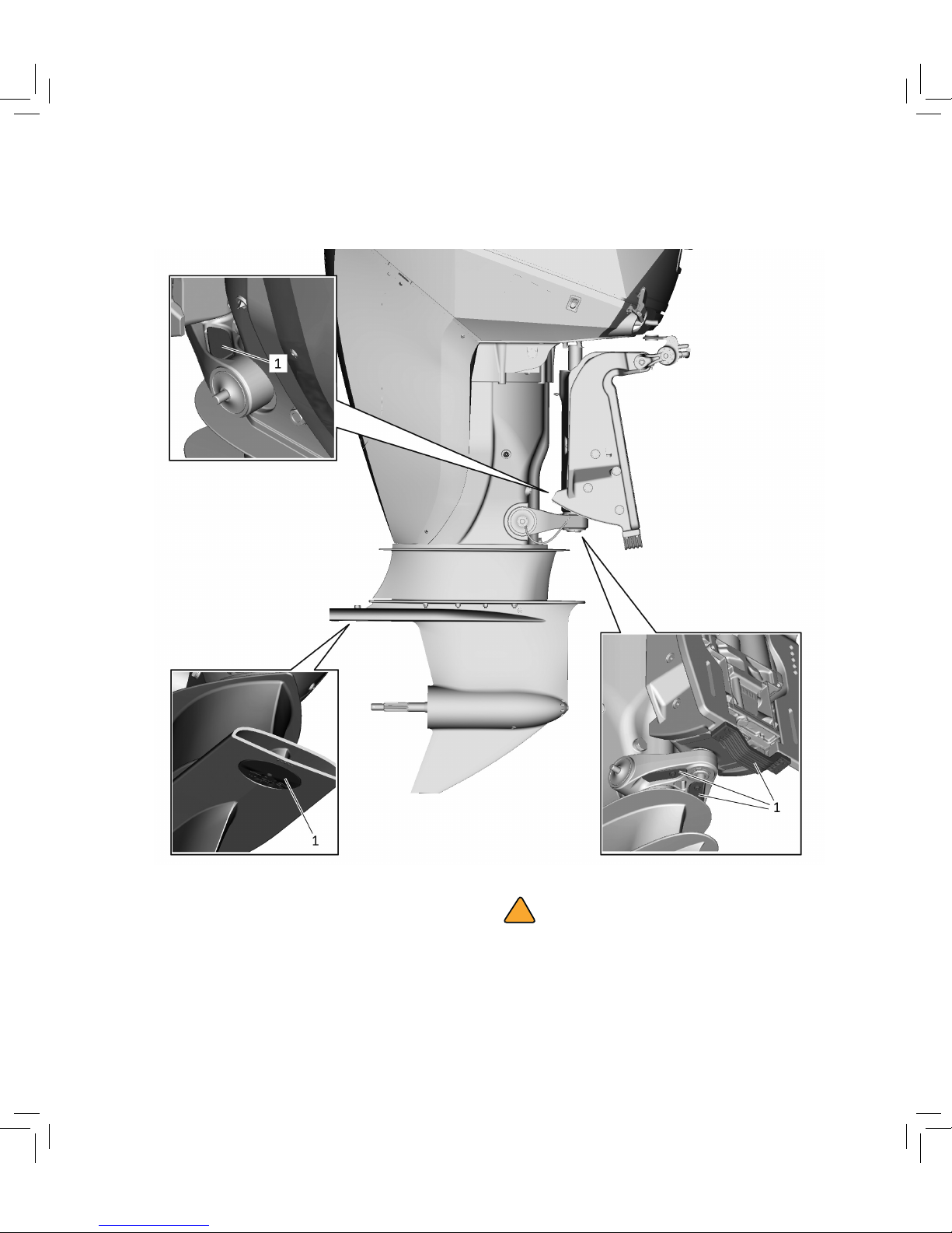
Inspect anodes
Anodes on the rig
The OXE Diesel outboard is protected from
corrosion by sacrificial anodes. Inspect the
external anodes (1) periodically and remove
scale from the surface.
Replace at service intervals or when anodes are
reduced to 2/3 their original size.
!
CAUTION
Do not paint anodes as it would make them
ineffective.
Page 47
41
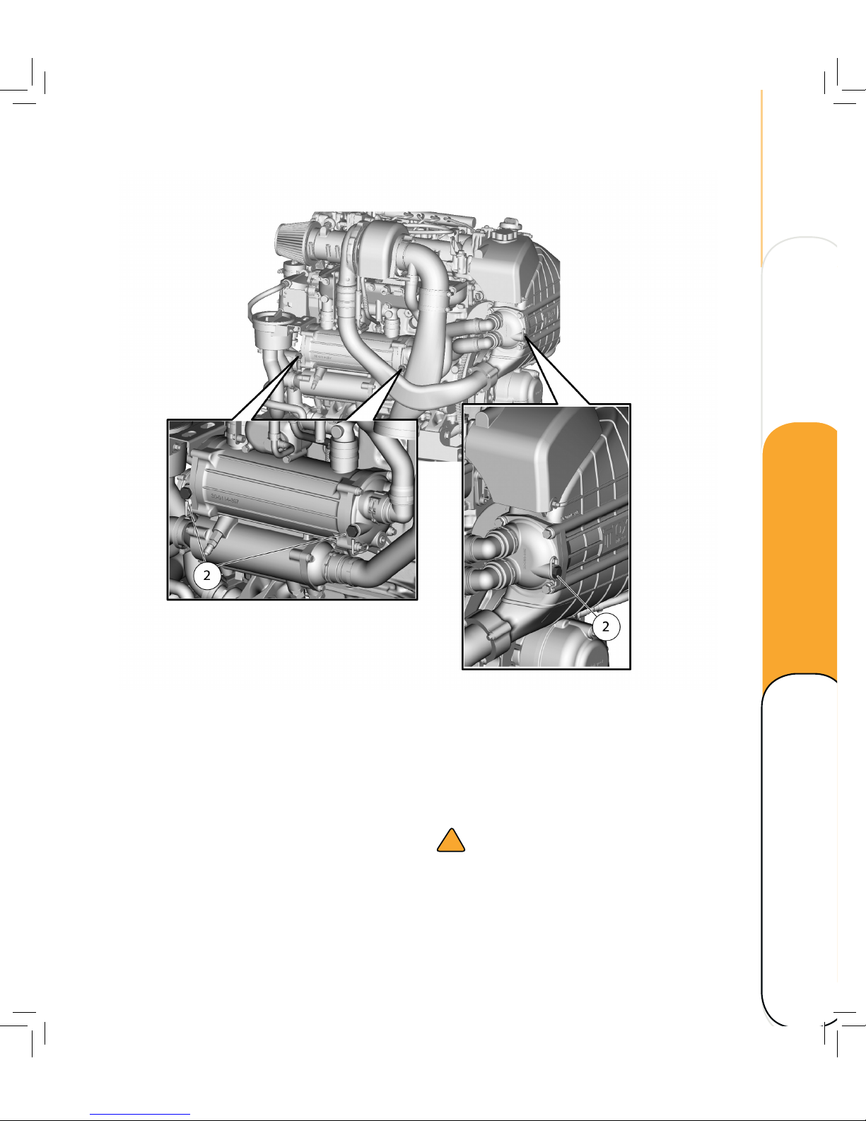
Anodes under the cowling
The heat exchanger and the intercooler are
located under the cowling. Both units are
equipped with sacrificial anodes to protect from
corrosion.
Inspect the anodes (2) periodically and remove
scale from the surface.
Replace at service intervals or when anodes are
reduced to 2/3 of their original size.
!
CAUTION
Ensure that anodes and threads are clean
before mounting.
Technical data Maintenance
Operating Overview
Page 48
42
MAINTENANCE
CHANGE FLUIDS AND FILTERS
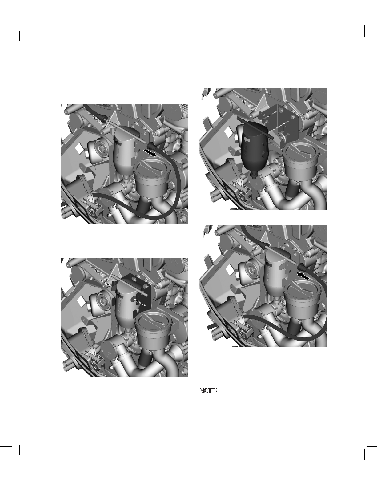
Change fuel filter
1. Apply a suitable container and drain fuel
from the filter and fuel lines.
2. Disconnect the fuel lines (1).
3. Press the clamps together.
4. Remove the filter.
5. Fit a new fuel filter into the holder and
connect the fuel lines. Ensure the flow
direction marked with an arrow on top of
filter.
NOTE! Dispose of the fuel-water mixture
according to local environmental legislation.
Page 49
43
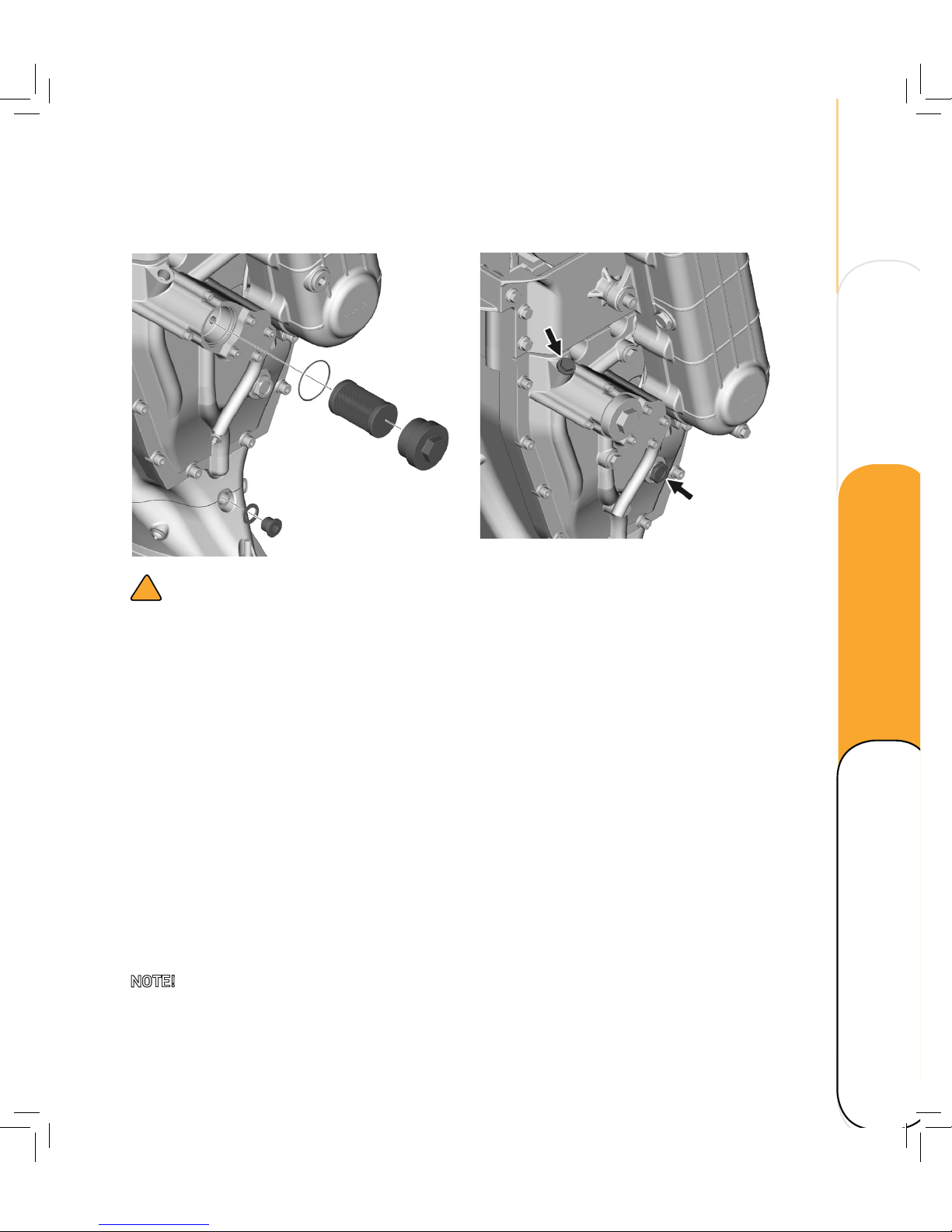
Replace hydraulic oil and filter
!
WARNING
The hydraulic oil filter is pressurised. Before
removing it the pressure must be released.
1. Turn the ignition ON and shi gear a couple
of times from forward to backward.
2. Tilt the outboard in order to minimize any
oil spill. Remove the oil plug and washer.
Drain the oil into a suitable container.
3. Carefully clean the area around the
hydraulic oil filter with pressurised air.
4. Remove the filter cap. Have a cloth nearby
to collect the oil in the filter.
5. Install a new filter and reinstall the filter
cap. Tightening torque 70 Nm (51.2 -lb).
6. Clean and reinstall the oil plug and seal.
Tightening torque 30 Nm (6.6 -lb).
NOTE! Discard used oil according to local
environmental legislation.
7. Unscrew the oil filling plug.
8. Use an oil filling device to fill up hydraulic
oil through the oil filler pipe.
9. Wipe clean.
10. Check the hydraulic oil level through the
sight glass.
11. Fill up if necessary.
12. Reinstal the the oil filling plug and seal.
Tightening torque 30 Nm (22.1 -lb).
Technical data Maintenance
Operating Overview
Page 50
44
MAINTENANCE
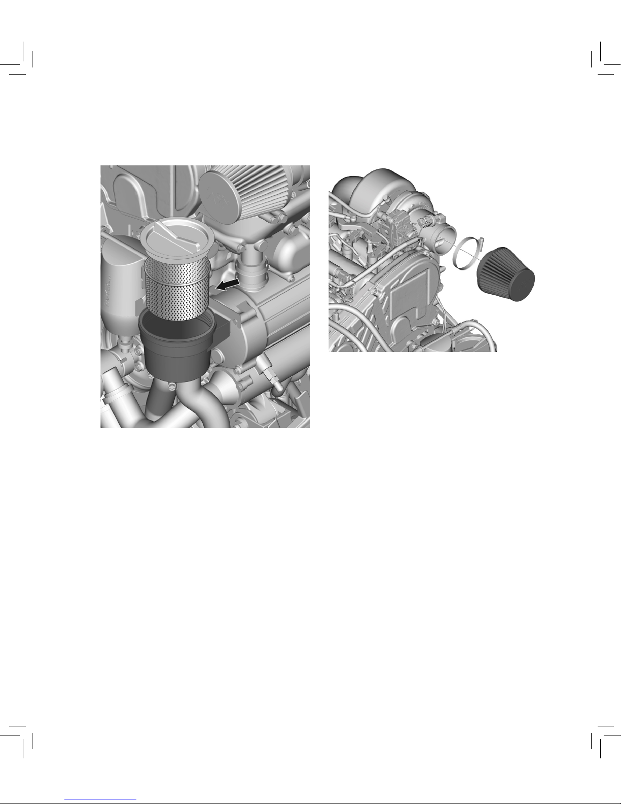
Replace air filter
1. Remove the clamp holding the filter.
2. Pull off the air filter.
3. Fit a new air filter.
4. Reinstall the clamp.
Clean seawater strainer
1. Remove the lid.
2. Pull out the strainer.
3. Clean the strainer, reinstall and close the
strainer lid.
Page 51
45
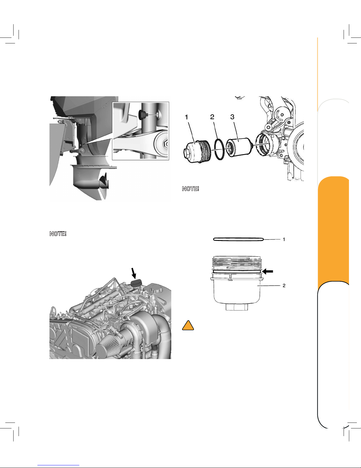
Change engine oil
1. Remove the oil draining plug and washer.
2. Drain the engine oil into a suitable
container.
NOTE! Discard used oil according to local
legislation.
3. Fit a NEW washer and tighten the oil
draining plug to 9 Nm (6.6 -lb).
4. Fill up the engine oil through the oil filler
neck.
5. Check engine oil level.
6. Close the filling cap and wipe clean.
Replace engine oil filter
NOTE! DO NOT use an open end wrench on the
hex on top of the oil filter cap. Use a hex socket!
1. Remove the oil filter cap (1) .
2. Remove the sealing (2).
3. Remove the oil filter element (3).
!
CAUTION
Lubricant must be applied to the threads of
the oil filter cap prior to installation. Failure
to lubricate the oil filter cap threads can
hinder later removal and cause possible oil
filter cap damage.
4. Install the NEW seal ring (1) with clean
engine oil to the oil filter cap (2).
Technical data Maintenance
Operating Overview
Page 52
46
MAINTENANCE
Change lower belt oil
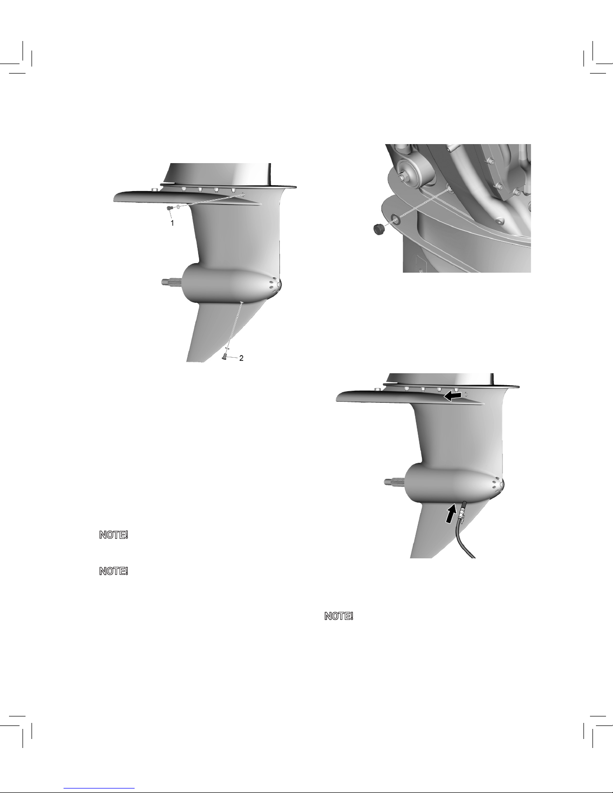
1. Remove the magnetic plug and washer (1)
above the anti-cavitation plate.
2. Remove the magnetic plug and washer (2)
under the propeller sha housing. Drain
the oil into a suitable container.
3. Check drained oil quality:
The oil should be red to dark red.
If the oil looks milky and foamy, water
has entered the lower housing. Check for
leakage!
NOTE! Discard belt oil according to local
legislation!
NOTE! Clean the magnetic oil plugs. Install new
washers.
4. Reinstall and tighten oil plug (2) to 9 Nm
(6.6 -l b).
5. Remove the sight glass and washer.
Fill up with belt oil until the oil comes
out at the upper oil plug (1). Refer to
Recommended fluids and grease.
6. Clean the sightglass. Install a new
washer. Tighten to 16 Nm (11.8 -l b).
1. Alternatively, use an oil filling device and
fill up the oil through the oil plug hole (2)
until oil comes out at oil plug hole (1).
NOTE! Clean the magnetic oil plugs. Install new
seals.
2. Remove the filling hose and tighten oil
plug (2) and (1) to 9 Nm (6.6 -lb).
Page 53
47
Change coolant
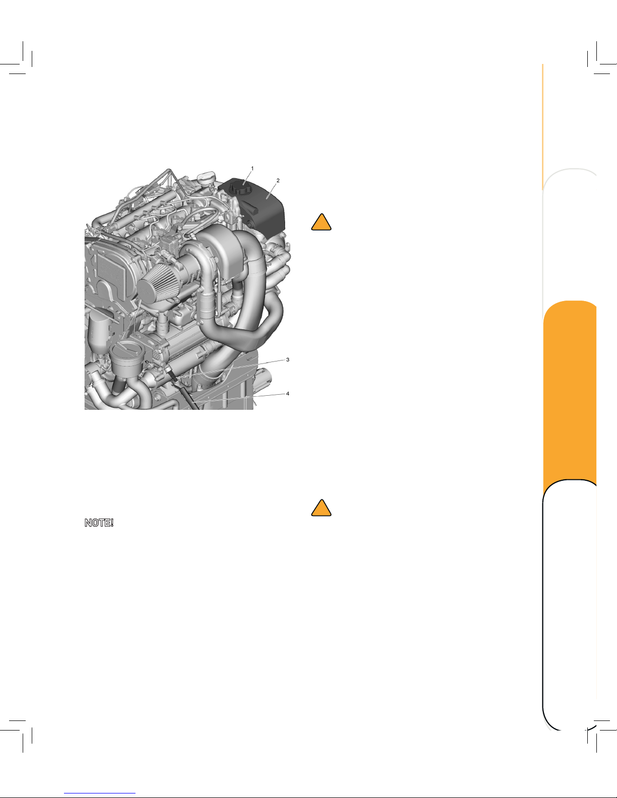
1. Remove the cap (1) of the expansion
tank (2).
2. Fit a hose (4) to the coolant drain
adapter (3).
3. Drain the coolant/water mixture into a
suitable container.
NOTE! Discard used coolant/water mixture
according to local legislation.
4. Remove the hose (4) from the drain
adapter.
5. Fill up with coolant/water-mixture
of 30% at the expansion tank cap up
to 4 cm below filling neck. Refer to
Recommended fluids and grease.
The cooling system of the engine is to be filled
with a mixture of distilled water and antifreeze
based on ethylene glycol and/or anticorrosion
additive.
!
WARNING!
Use only approved fuels, lubricants etc.
see “Recommended fluids and grease”.
Otherwise the manufacturer’s warranty will
become null and void.
Coolant must be added at the filler cap only.
Do not add cold coolant to a warm engine.
Ensure that the mixing ratio “water-antifreeze”
is preserved.
6. Slowly fill up with coolant via filler
neck on expansion tank until fluid level
has reached just above the divider in
expansion tank.
7. Let engine run at a speed of 2,000 rpm for
approx. 15 minutes.
8. Switch off engine, carefully turn the cap to
relieve pressure.
!
DANGER!
Do NOT open cap until pressure is released.
Risk of scalding and burning yourself!
9. Top up to 4 cm below filling neck.
10. Before the next engine start-up (with the
engine cold) check the coolant level and
top up if necessary.
11. Repeat this procedure until no more
coolant can be added.
Technical data Maintenance
Operating Overview
Page 54
48
MAINTENANCE
Replace thermostat
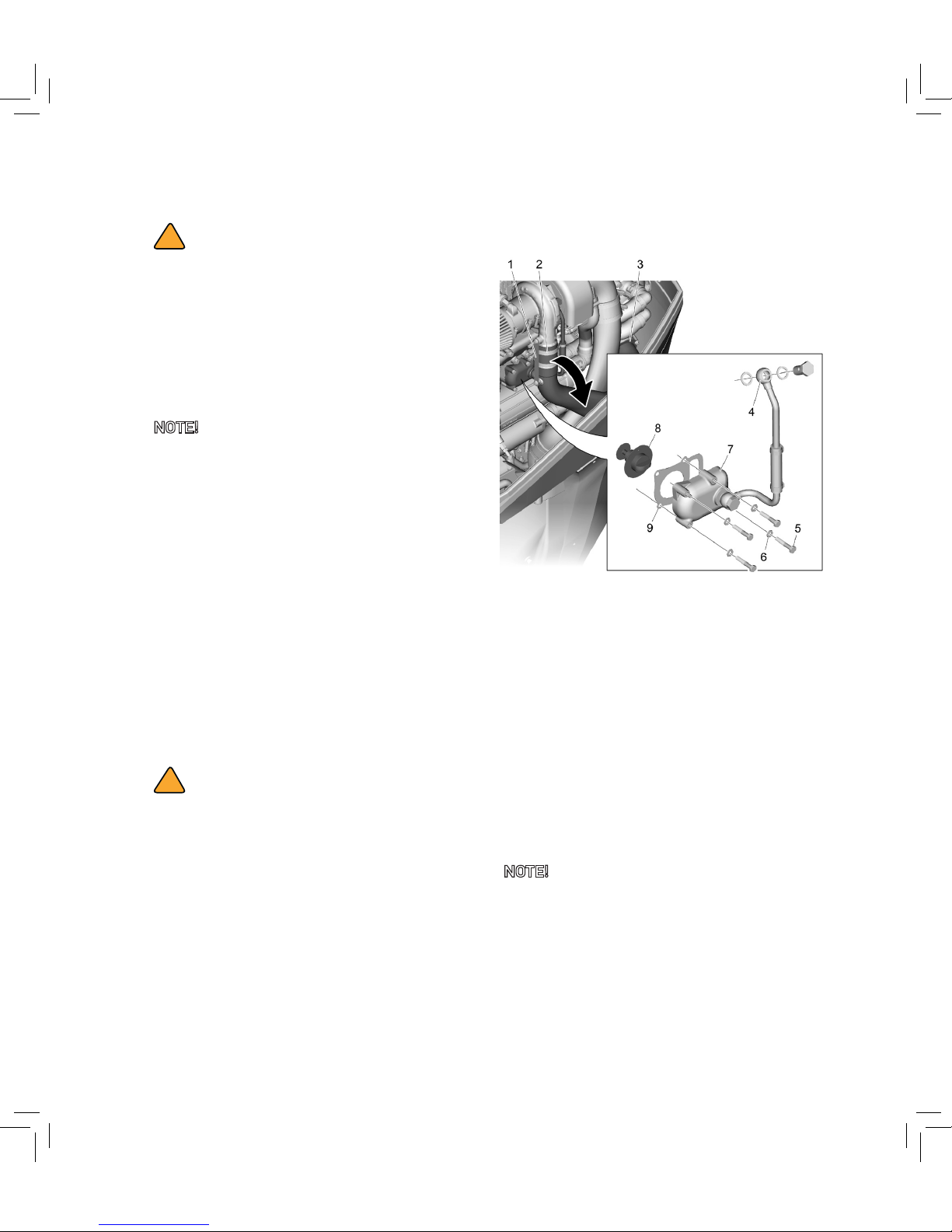
1. Remove the pressure pipe retainer (1)
and the clamp (2).
2. Remove the Pressure pipe intercooler
retainer (3).
3. Loosen the pressure pipe assembly.
4. Remove the turbo water out pipe (4).
5. Loosen screws (5), washers (6), and
thermostat housing lid (7).
6. Remove thermostat (8) and gasket (9).
7. Clean thermostat housing.
8. Install a new thermostat.
NOTE! Install a new gasket.
9. Reinstall the thermostat housing lid with
4 screws and washers.
10. Fill up according to Filling coolant.
!
DANGER!
If, in an exceptional case, the coolant
level has to be checked in an engine that
has reached operating temperature, first
carefully turn the cap (large cap) with safety
valve to the first stop, let off pressure, then
open carefully.
NOTE! Do not open the cooling system when
the engine is at operating temperature. This
causes a pressure loss in the cooling system.
If the cooling system has been opened when
the engine is at operating temperature this can
lead to the alarm “pressure in the expansion
tank” when the engine is then put into operation
and to a reduction in the engine output.
Coolant pressure in the expansion tank is only
built up again when the engine has cooled
down.
The cooling system must therefore only be filled
up when the engine is cold.
!
WARNING!
When the cover is opened with working
valves, there is a danger that it is not
properly sealed when closed again. The
required overpressure is no longer set up in
the cooling system. Premature simmering
and loss of coolant result. To avoid damage
to the engine, this cover should as a general
rule only be opened in exceptional cases and
then replaced by a new one.
Page 55
49
Replace propeller
!
WARNING
Do not use any body parts to hold the
propeller when loosening or tightening the
propeller nut.
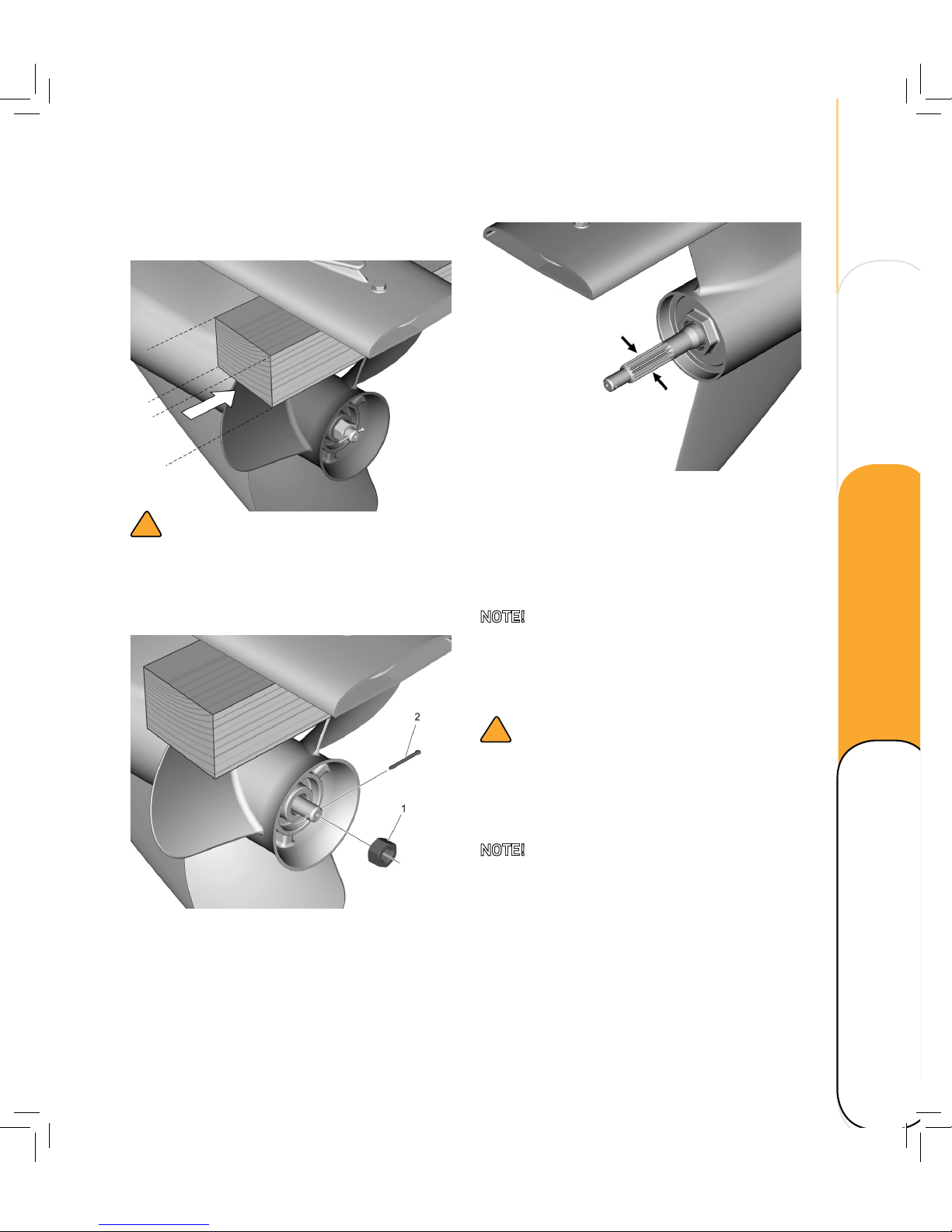
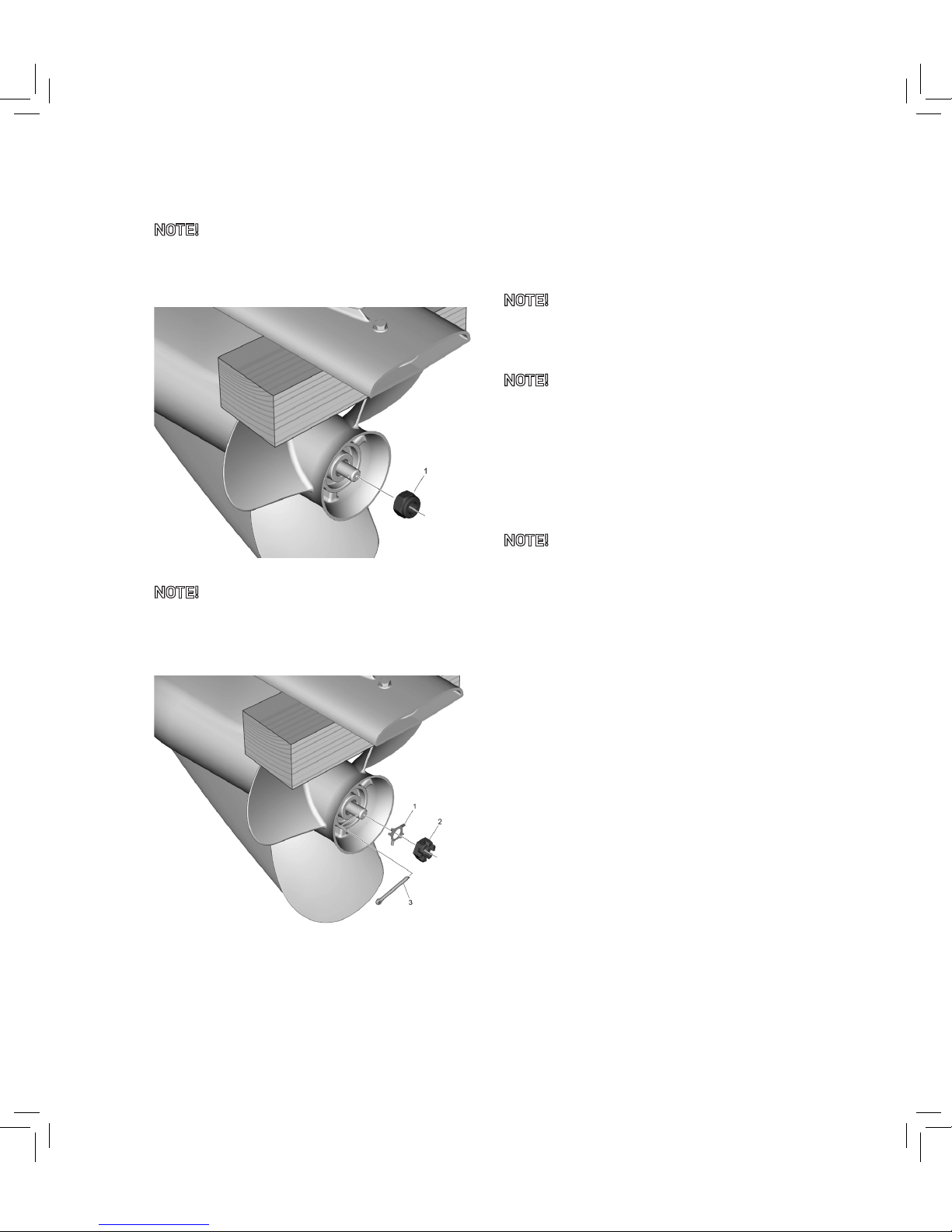
1. Straighten the cotter pin (2) and pull it out
using a pair of pliers.
2. Remove the propeller nut (1).
3. Remove the propeller and propeller
washer.
4. Apply marine grease according to table
Recommended fluids and grease to the
propeller sha.
5. Install the propeller washer and propeller
on the propeller sha.
NOTE! Be sure to install the propeller washer
before installing the propeller, otherwise
the lower case and propeller boss could be
damaged.
!
CAUTION
Be sure to use a new cotter pin and bend the
ends over securely. Otherwise the propeller
could come off during operation and be lost.
NOTE! We recommend a hub kit when
mounting a propeller. Contact your OXE Diesel
dealer!
Technical data Maintenance
Operating Overview
Page 56
50
MAINTENANCE
NOTE! Some outboards are equipped with a
Nyloc locking nut (1) and do not have a cotter
pin. Do NOT reuse a Nyloc locking nut!
NOTE! Some models use a retainer (1) and
a castlelated nut (2) combined with a
cotter pin (3).
6. Tighten the propeller nut to the specified
torque.
Propeller nut tightening torque:
75.0 Nm (55.6 -lb).
7. Align the propeller nut with the propeller
sha hole. Insert a new cotter pin in the
hole and bend the cotter pin ends.
NOTE! Do not reuse the cotter pin installed.
Otherwise the propeller can come off during
operation.
NOTE! If the propeller nut does not align with
the propeller sha hole aer tightening to the
specified torque, tighten the nut further to align
it with the hole.
Ensure that the propeller is undamaged and
rotates freely of the lower housing.
NOTE! Always have an extra propeller including
necessary tools on board.
Page 57
51
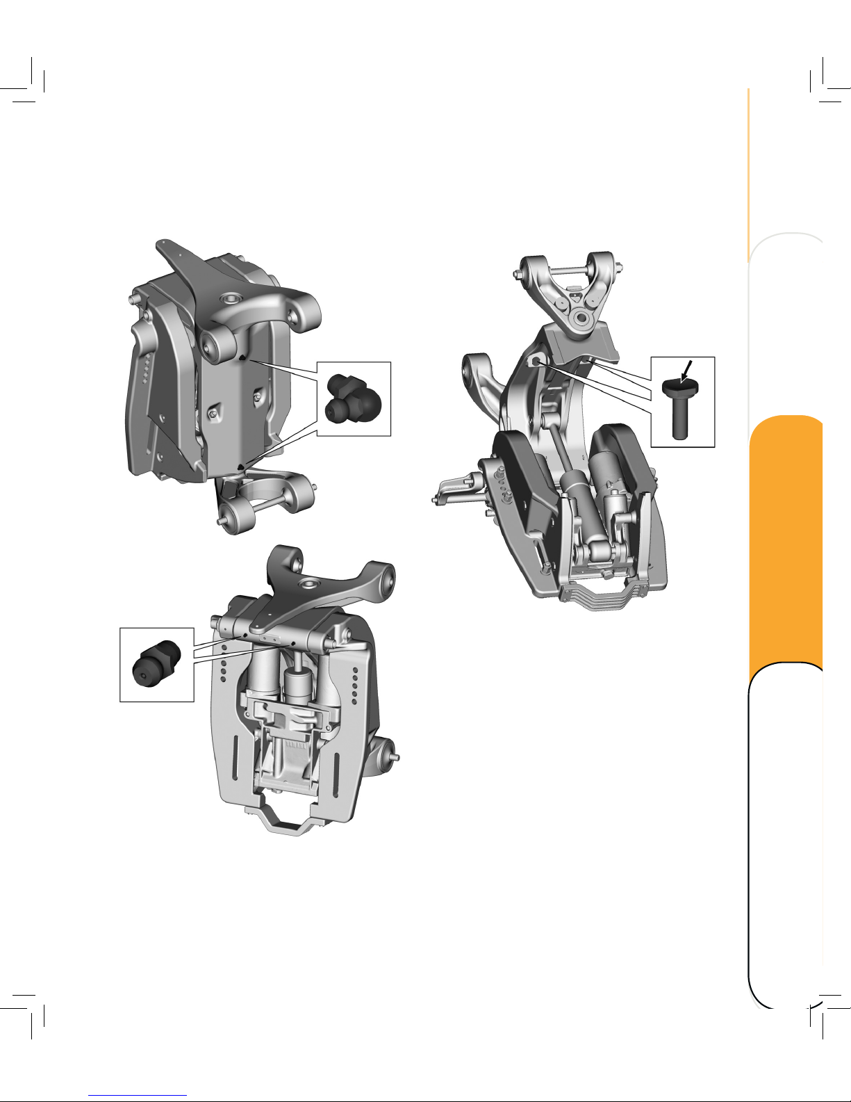
LUBRICATING AND GREASING
Power trim and tilt unit
1. Use a grease gun and fill up with
recommended grease until the grease
comes out at the joints or ends of sha.
Refer to Recommended fluids and
grease.
2. Fill the seatings with grease for smoother
tilt operation. Use grease according to
Recommended fluids and grease.
Technical data Maintenance
Operating Overview
Page 58
52
MAINTENANCE
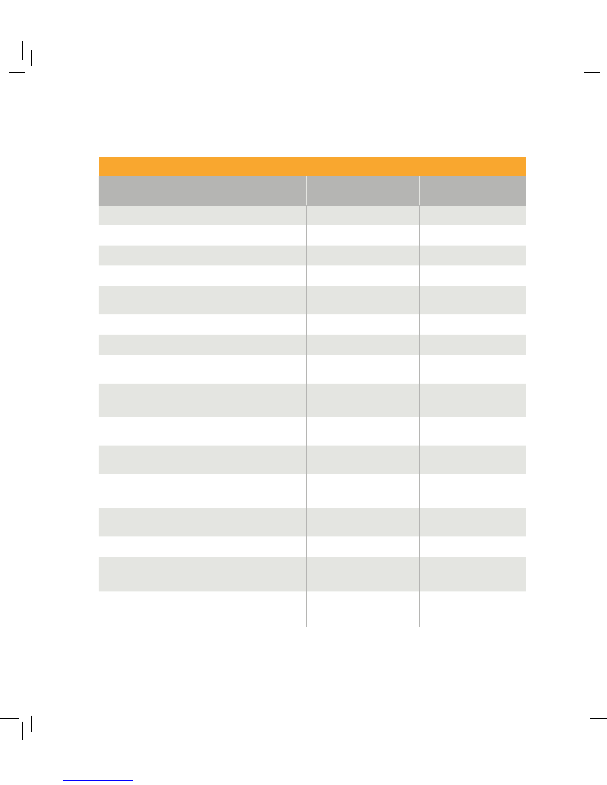
MAINTENANCE SCHEDULE
Checklist
1st inspection, aer 50 h Check Fill up Clean Change/
Replace
Refer to
Hydraulic oil and filter X
Change fluids and filters
O-ring, gearbox oil filter X
Change fluids and filters
Magnetic oil plug and washer, gear box X
Change fluids and filters
Coolant level and mixture X Check cooling system
Fluid level, power trim and tilt unit (PTT-unit)
X
Check fluid level in power
trim and tilt unit
Magnetic plug and washer, power trim
x
Checks before start-up
Sea water strainer X Change fluids and filters
Upper belt tension X
Service Manual
Check upper belt tension
Upper belt oil X
Service Manual
Change upper belt oil
Magnetic plug and washer, upper belt housing X Service Manual
Change upper belt oil
Lower belt tension X
Service Manual
Check lower belt tension
Lower belt oil X
Service Manual
Change lower belt oil
Magnetic oil plug and washer, lower belt X Service Manual
Change lower belt oil
Display/gauges, function X Display manual
Upper belt oil, magnetic plug, washer X
Service Manual
Change upper belt oil
Lower belt oil, magnetic plug, washer
X
This publication
Change lower belt oil
Page 59
53
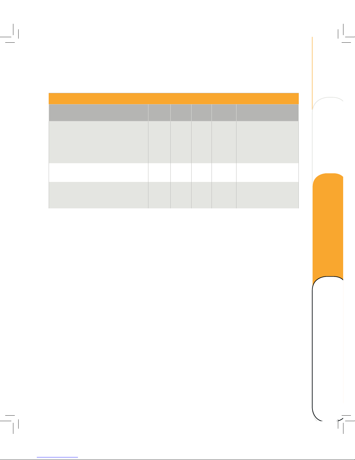
Checklist
1st inspection, aer 50 h Check Fill up Clean Change/
Replace
Refer to
Starting and warming up engine
– Water/oil/fuel leakage
– Power trim, function and leakage
– No DTCs are triggered (diagnostic tool)
– Unusual engine/transmission sounds
X
Stop engine
– Engine oil and filter
X X
Change fluids and filters
Restart engine
– Oil pressure
– Oil leakage
X Display manual
Technical data Maintenance
Operating Overview
Page 60
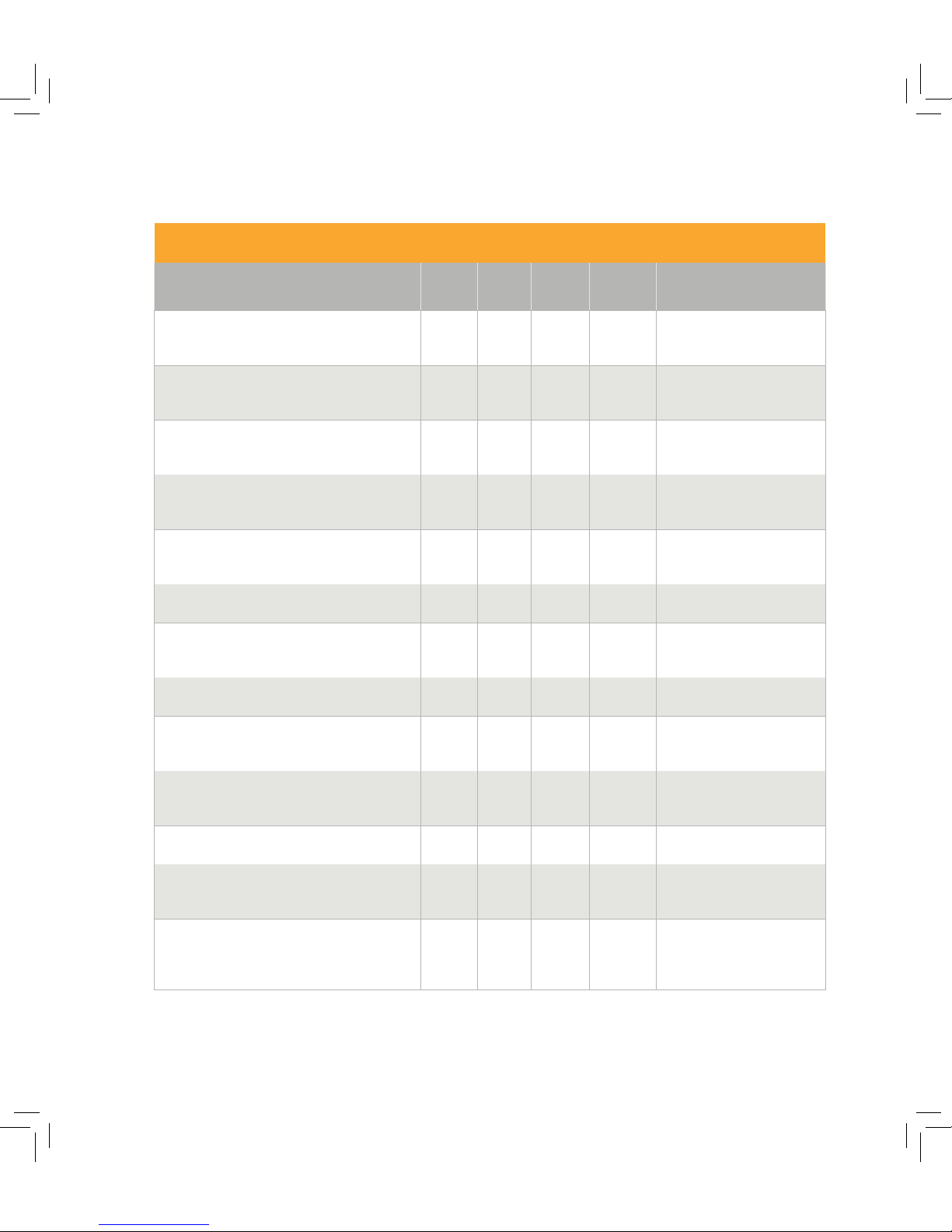
54
MAINTENANCE
Checklist
Every 200 h or once a year Check Fill up Clean Change/
Replace
Refer to
Engine oil and filter
X
This publication
Change fluids and filters
Fluid level power trim
X
This publication
Checks before start-up
Upper belt tension
X
Service Manual
Check upper belt tension
Lower belt tension
X
Service Manual
Check lower belt tension
Coolant level and mixture
X
This publication
Check cooling system
Crank case ventilation, hoses and clamps X Check hoses and clamps
Air filter
X
This publication
Change air filter
Display/gauges function X Display manual
Turbo charger
X
Service Manual
Air filter replacement
Exhaust tube
X
This publication
Engine views
Alternator drive belt tension X Self adjusting
Seawater strainer
X
This publication
Change fluids and filters
Sea water pump, impeller
X
Service Manual
Seawater pump impeller
replacement
Page 61
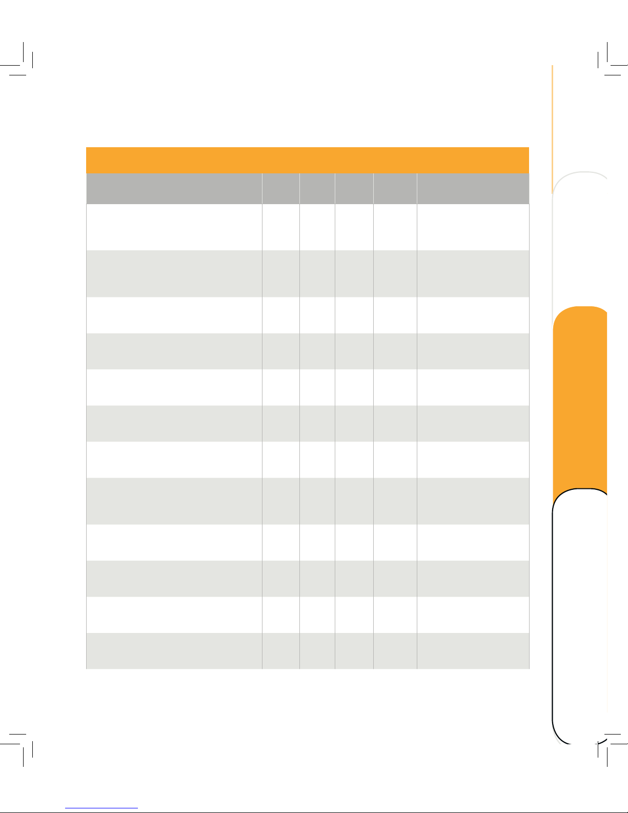
55
Checklist
Every 200 h or once a year Check Fill
up
Clean Change/
Replace
Refer to
Gasket, Sea water pump
X
Service Manual
Seawater pump impeller
replacement
Anodes. Intercooler, heat exchanger, transom
mount, anti-cavitation plate X
This publication
Checking and other
maintenance
Fuel filter
X
This publication
Change fluids and filters
Gearbox, oil and filter, gasket
X
Service Manual
Hydraulic oil filter repl.
Gearbox, magnetic plug and washer
X
Service Manual
Hydraulic oil filter repl.
Upper belt oil, magnetic plug, washer X
Service Manual
Change upper belt oil
Lower belt oil, magnetic plug, washer
X
This publication
Change lower belt oil
Painting X
This publication
Checking and other
maintenance
Inspection, exhaust hose and coolant hoses X
Service Manual
Engine views
Hoses/pipes, connections, hose clamps X
Service Manual
Engine views
Condition of rubber hoses X
Service Manual
Engine views
Hydraulic hoses, connections (leakage, wear,
aging)
X Service Manual
Engine views
Technical data Maintenance
Operating Overview
Page 62

56
MAINTENANCE
Checklist
Each 800 h/once every 3rd year
minimum
Check Fill up Clean Change/
Replace
Refer to
Engine oil X
This publication
Change fluids and
filters
Fluid level, Power trim X
This publication
Before start-up
Upper belt tension X
Service Manual
Check upper belt
tension
Lower belt tension X
Service Manual
Check lower belt
tension
Coolant level and mixture X
This publication
Checking and other
maintenance
Crank case ventilation, hoses and clamps X
Check hoses and
clamps
Air filter X
This publication
Change fluids and
filters
Display/Gauges, function Display Manual
Turbo charger X X
Service Manual
Air filter replacement
Trim pistons, hoses, hydraulic hoses.
Leakage X
Service Manual
Check trim and tilt
system
Hoses, hydraulic hoses. Leakage X
Service manual
Engine views
Page 63
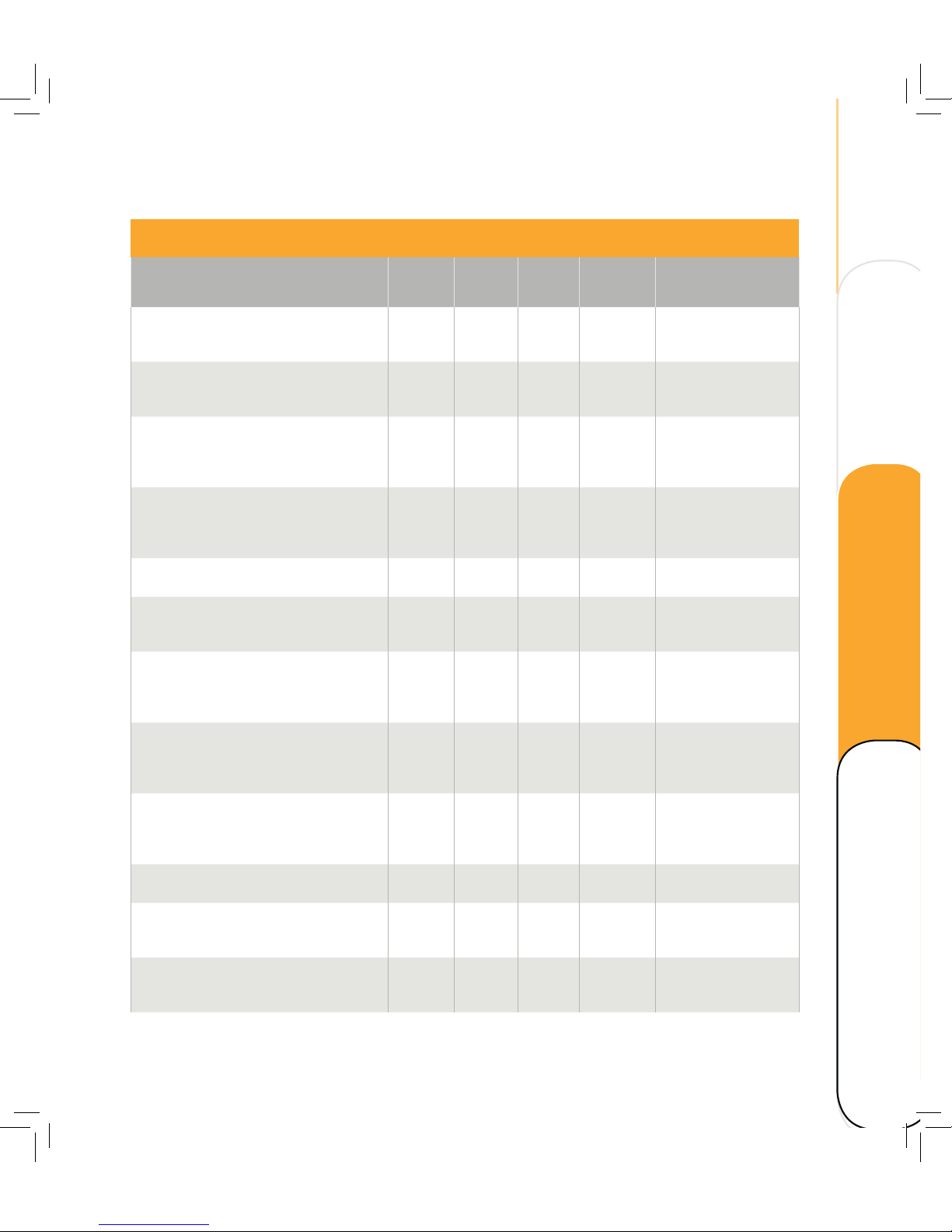
57
Checklist
Each 800 h/once every 3rd year
minimum
Check Fill up Clean Change/
Replace
Refer to
Upper belt oil X
Service Manual
Change upper belt oil
Upper belt assembly, oil plug, washer X
Service Manual
Change upper belt oil
Lower belt oil X X
This publication
Change fluids and
filters
Lower belt, oil plug, washer
x
This publication
Change fluids and
filters
Bushings/shas in transom mount X Installation Manual
Propeller sha, check straightness and
splines condition
X
Service Manual
Lower belt repl.
Alternator drive belt X
Service Manual
Alternator drive belt
replacement
Heat exchanger X
Service Manual
Cleaning heat
exchanger
Intercooler, anode X
This publication
Checking and other
maintenance
Cables, connectors, and cable glands X Installation Manual
Exhaust hose and coolant hoses X
Service Manual
Engine views
Hoses/pipes, connections and hose clamps
X
Service Manual
Engine views
Technical data Maintenance
Operating Overview
Page 64
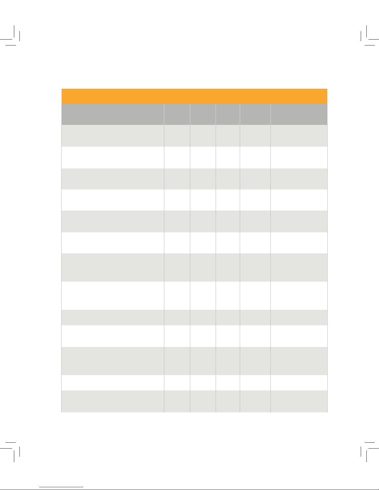
58
MAINTENANCE
Checklist
Each 800 h/once every 3d year
minimum
Check Fill up Clean Change/
Replace
Refer to
Coolant
X
Service Manual
Drain and fill coolant
Upper belt housing, gear pulleys, bearings,
gaskets and sealings, engine adapter sha
X
Service Manual
Upper belt repl.
Upper belt X
Service Manual
Upper belt repl.
Upper belt X
Service Manual
Upper belt repl.
Upper belt seals X
Service Manual
Check belt pulley seals
Gearbox sha in, pulleys and splines
X
Service Manual
Lower belt repl.
Gearbox/propeller sha, pulleys and splines,
wear and straightness
X
Service manual
Lower belt
replacement
Gear, function and wear X
Service Manual
Lower belt
replacement
Clutch mechanism, perform pressure test X Service Manual
Gearbox seals X
Service Manual
Lower belt and related parts
X
Service Manual
Lower belt
replacement
Lower belt seals X Service Manual
Propeller sha oil seal
X
Service Manual
Propeller replacement
Page 65
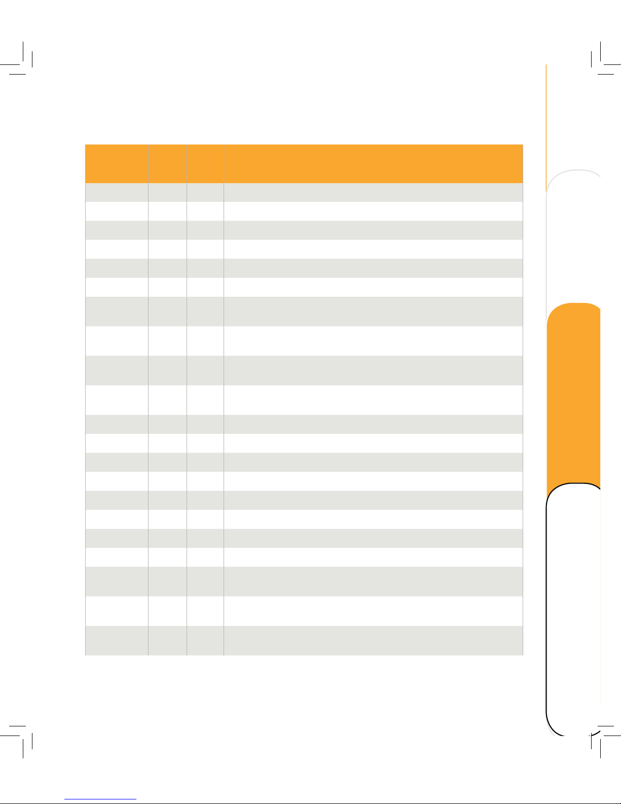
59
FAULT CODES
NIRA Internal
fault code
J1939
SPN
J1939
FMI
Description
0 157 3 Fuel rail pressure sensor - Voltage above normal, or shorted to high source
1 157 4 Fuel rail pressure sensor - Voltage below normal, or shorted to low source
4 102 3 Manifold air pressure sensor - Voltage above normal, or shorted to high source
5 102 4 Manifold air pressure sensor - Voltage below normal, or shorted to low source
8 100 3 Engine oil pressure sensor - Voltage above normal, or shorted to high source
9 100 4 Engine oil pressure sensor - Voltage below normal, or shorted to low source
12 Air filter differentail pressure sensor - Voltage above normal, or shorted to high
source
13 Air filter differentail pressure sensor - Voltage below normal, or shorted to low
source
24 171 3 Ambient air temperature sensor - Voltage above normal, or shorted to high
source
25 171 4 Ambient air temperature sensor - Voltage below normal, or shorted to low
source
26 Trim angle sensor - Voltage above normal, or shorted to high source
27 Trim angle sensor - Voltage below normal, or shorted to low source
30 Hydraulic oil pressure - Voltage above normal, or shorted to high source
31 Hydraulic oil pressure - Voltage below normal, or shorted to low source
76 DG_FNO_ECU_VREF_AIN_HIGH
77 DG_FNO_ECU_VREF_AIN_LOW
78 Hydraulic oil temperature - Voltage above normal, or shorted to high source
79 Hydraulic oil temperature - Voltage below normal, or shorted to low source
92 105 3 Manifold air temperature sensor - Voltage above normal, or shorted to high
source
93 105 4 Manifold air temperature sensor - Voltage below normal, or shorted to low
source
94 110 3 Engine coolant temperatur sensor - Voltage above normal, or shorted to high
source
Technical data Maintenance
Operating Overview
Page 66
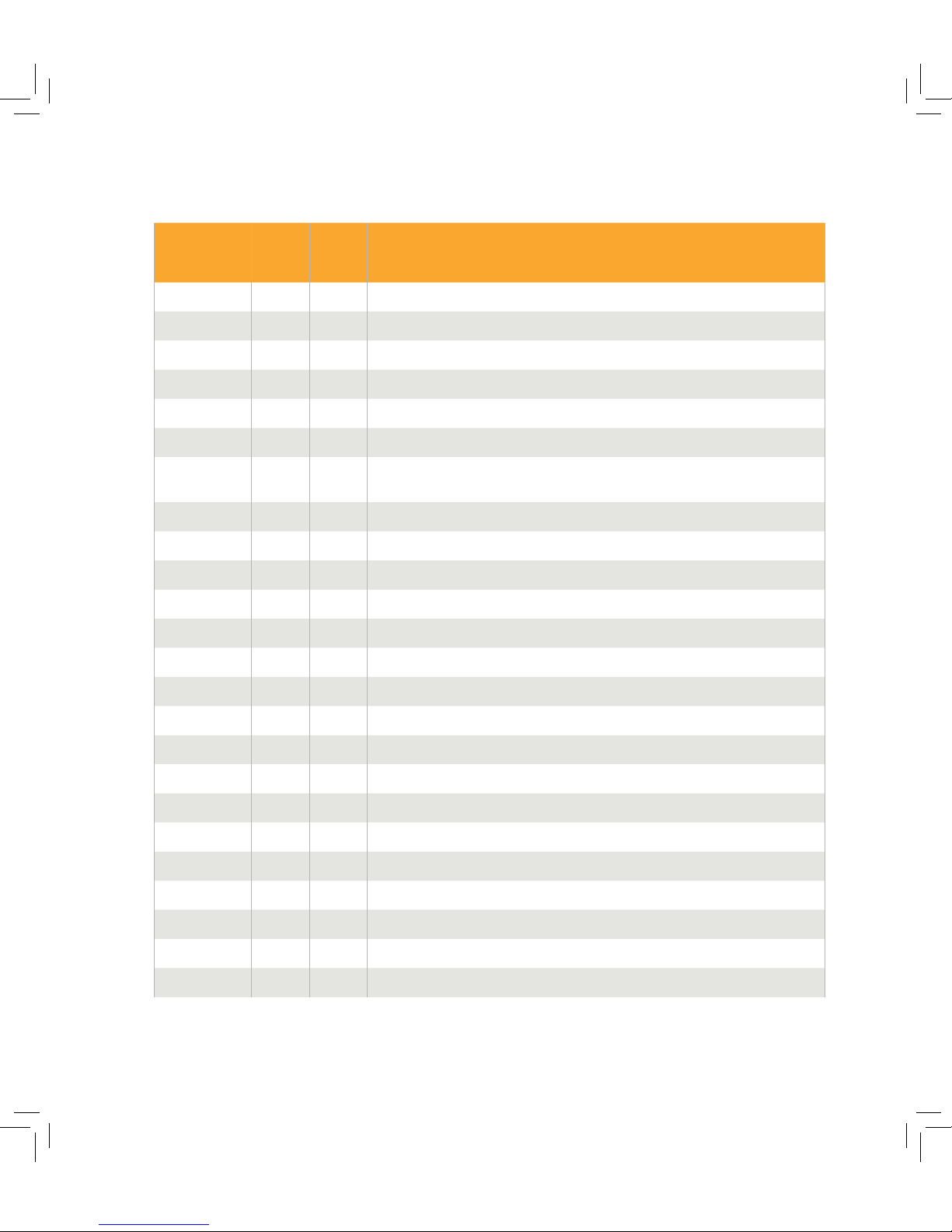
60
MAINTENANCE
NIRA Internal
fault code
J1939
SPN
J1939
FMI
Description
160 DG_FNO_GEAR_ACTUATION_FAULT
161 DG_FNO_HB1_ELECTRICAL_FAULT
162 DG_FNO_HB2_ELECTRICAL_FAULT
163 DG_FNO_HB3_ELECTRICAL_FAULT
164 DG_FNO_HB4_ELECTRICAL_FAULT
165 Main relay - Electrical fault
95 110 4 Engine coolant temperatur sensor - Voltage below normal, or shorted to low
source
98 Engine oil temperature sensor - Voltage above normal, or shorted to high source
99 Engine oil temperature sensor - Voltage below normal, or shorted to low source
106 108 3 Ambient pressure sensor - Voltage above normal, or shorted to high source
107 108 4 Ambient pressure sensor - Voltage below normal, or shorted to low source
108 1136 ECU temperature sensor - Voltage above normal, or shorted to high source
109 1136 ECU temperature sensor - Voltage below normal, or shorted to low source
112 3509 3 ECU 5V sensor supply 1 - Voltage above normal, or shorted to high source
113 3509 4 ECU 5V sensor supply 1 - Voltage below normal, or shorted to low source
114 3510 3 ECU 5V sensor supply 2 - Voltage above normal, or shorted to high source
115 3510 4 ECU 5V sensor supply 2 - Voltage below normal, or shorted to low source
116 158 3 Battery potential - Voltage above normal
117 158 4 Battery potential - Voltage below normal
137 157 0 Fuel rail pressure - Data valid but above normal operational range
138 157 14 Fuel rail pressure - Control error
139 102 0 Manifold air pressure - Data valid but above normal operational range
140 102 14 Manifold air pressure - Control error
142 641 14 Turbo actuator -C ontrol error
Page 67
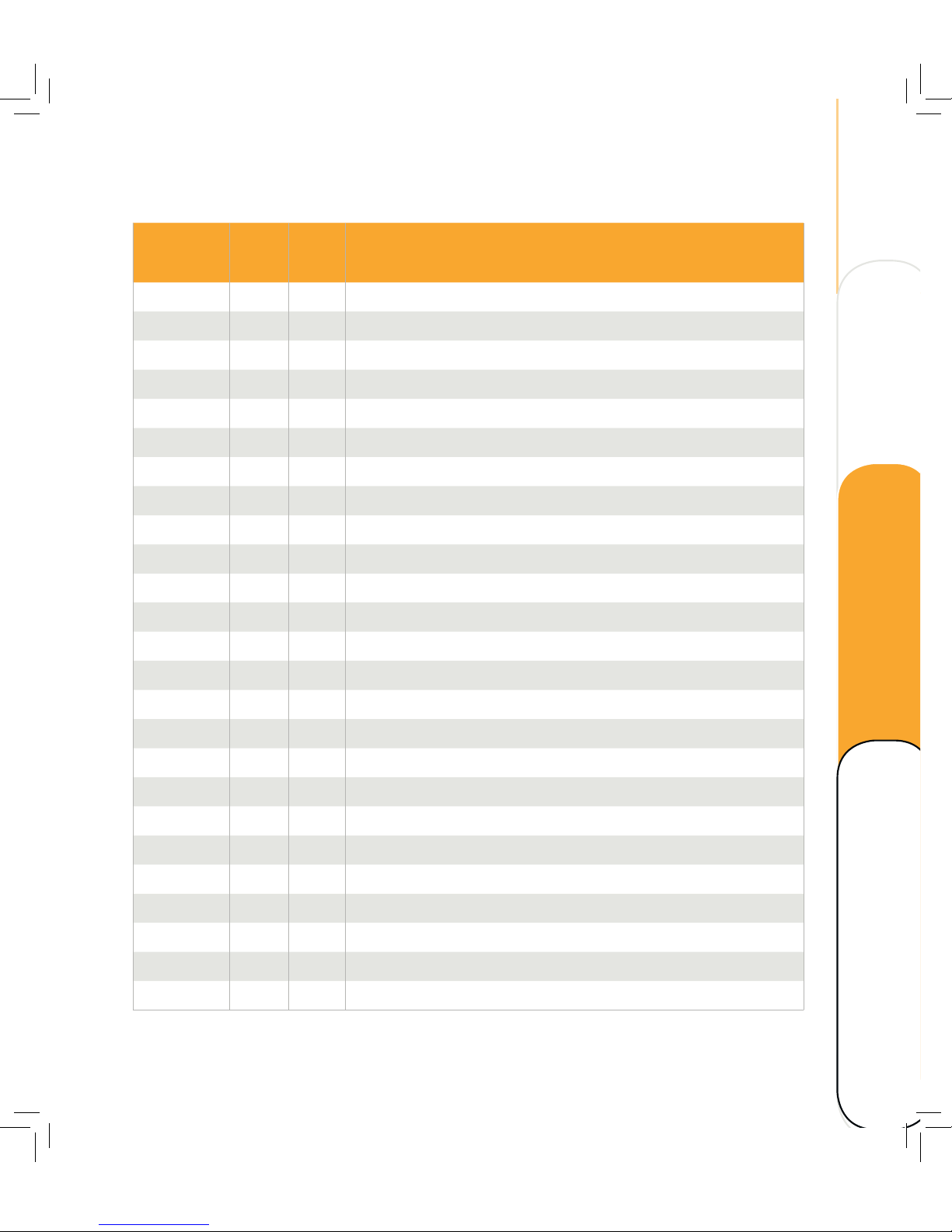
61
NIRA Internal
fault code
J1939
SPN
J1939
FMI
Description
148 Trim position pump - Control error
150 100 1 Engine oil pressure - Data valid but below normal operational range
151 651 5 Fuel injector 1, Cylinder 1 - Open curcuit
152 652 5 Fuel injector 2, Cylinder 2 - Open curcuit
153 653 5 Fuel injector 3, Cylinder 3 - Open curcuit
154 654 5 Fuel injector 4, Cylinder 4 - Open curcuit
159 DG_FNO_GEAR_POSITION_FAULT
166 Fuel pump relay - Electrical fault
167 Trolling valve - Electrical fault
174 Hydraulic oil pressure - Data valid but above normal operational range
175 Hydraulic oil pressure - Data valid but below normal operational range
176 Hydraulic oil temperature - Data valid but above normal operational range
177 DG_FNO_OIL_LEVEL_LOW
179 97 31 DG_FNO_WATER_IN_FUEL
188 110 0 DG_FNO_COOLANT_TEMPERATURE
189 1136 0 DG_FNO_ECU_TEMPERATURE
190 175 0 DG_FNO_OIL_TEMPERATURE
191 2899 12 DG_FNO_GPC_MODULE
192 5324 31 DG_FNO_GPC_MODULE
193 DG_FNO_GPC_MODULE_COM
194 2433 2433 Exhaust gas temperature - Data valid but above normal operational range
196 171 171 Ambiant air temperature - Data valid but above normal operational range
198 107 107 Air filter pressure sensor - Data valid but below normal operational range
199 DG_FNO_COOLANT_LEVEL_LOW
200 Control head CAN RX time-out
Technical data Maintenance
Operating Overview
Page 68

62
MAINTENANCE
TROUBLE SHOOTING
Refer to Service Manual.
Page 69
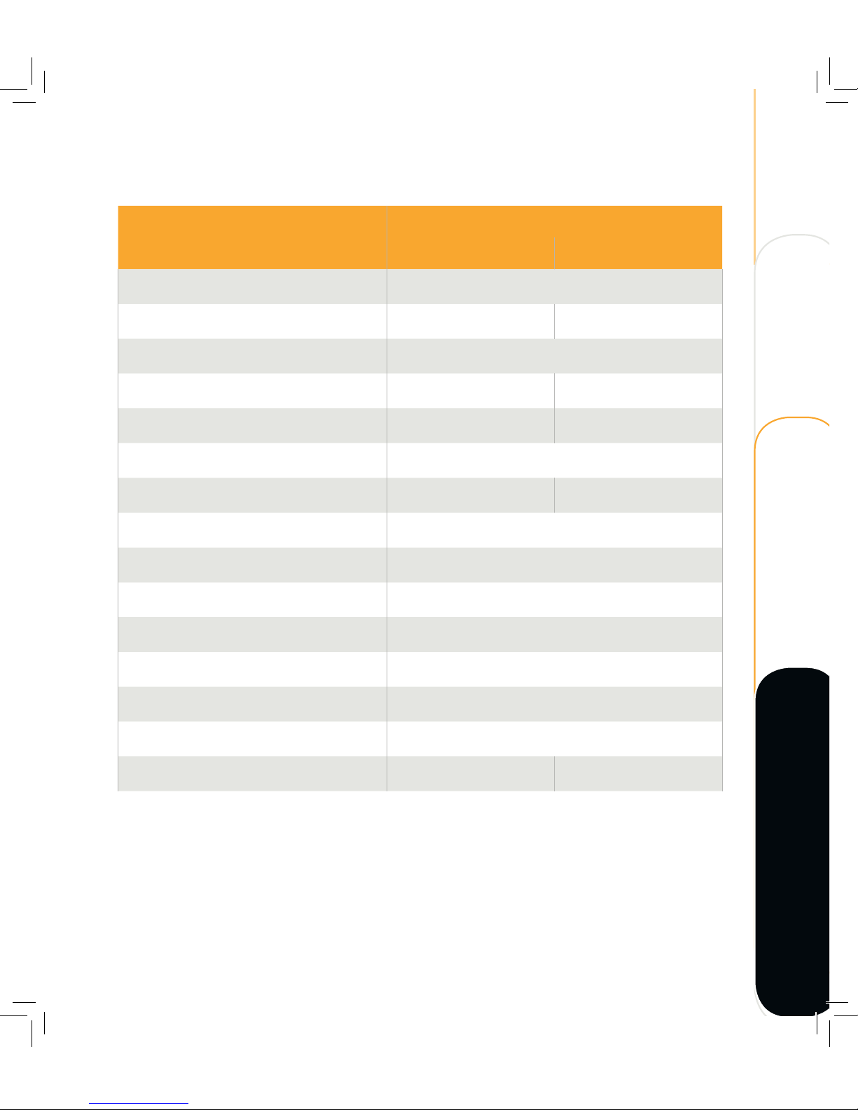
63
TECHNICAL DATA
Application
Specification
Metric Imperial
Engine Type Diesel, L4. Refer to Recommended fluids and grease
Displacement 1956 cc 122 cu in
Intake Turbocharged, intercooled
Maximum Power at Engine Speed 147 kW at 4100 RPM 200 HP at 4100 RPM
Maximum Torque at Engine Speed 415 Nm at 2500 RPM 306 lb at 2500 RPM
Fuel Diesel
Weight 340 kg 2459 lb
Alternator output 130 A
Rig length 20", 25" or 30"
Cooling Closed cooling circuit, heat exchanger/seawater
Starting Electric
Shi Electro-hydraulic
Clutch Hydraulic multi-friction plate
Gear ratios 1.73:1 and 2.17:1
Dimensions (25" leg), LHW 100 x 188 x 68 cm 39 x 74 x 27 in
Technical data Maintenance
Operating Overview
Page 70
64
TECHNICAL DATA
RECOMMENDED FLUIDS AND GREASE
Quantity
Fluid Quality
Metric Imperial
Fuel EN 590 (with national environmental and cold weather
standards)
ASTM D 975 No. 1 and No. 2
JIS KK 2204
- -
Engine oil
change incl.
filter
5w-30 dexos2 API SM/CF GM-LL-A025 /
B025 ACEA A3/B4
5.5 liters
1)
5.8 quarts
Hydraulic oil Fully Synthetic Dual Clutch Transmission Fluid - DCT 2.5 liters
1)
2.1 quarts
Cooling system,
coolant mixture
GM Long-Life Coolant - Specification B040 1065/
Distilled water (30/70)
7.5 liters 7.9 quarts
Grease DIN 51502:KP2.5K-20
ISO 6743: ISO-L-XBCEB2.5
- -
Power trim and
tilt unit
ATF Dexron II 0.5-0.7 liters 0.52-0.73 quarts
Upper belt oil Fully Synthetic Transmission Fluid - ATF / Dexron HP 0.33 liters 0.34 quarts
Lower belt oil Fully Synthetic Transmission Fluid - ATF / Dexron HP 2 liters 2.1 quarts
NOTE! Only use fuels, lubricants etc. in accordance with Cimco Marine AB regulations. Otherwise
the manufacturer’s liability for defects will not apply!
1)
Refer to Service Manual
Page 71

65
DIESEL FUELS
The composition of the fuels is vital for
operation of the OXE outboard, its service
life, and emissions. To meet the performance
specified and to run the boat cleanly and quietly,
it is important that fuel as recommended in
table Recommended fluids and grease is
used.
NOTE! The fuel must meet national and
international standards.
OXE Diesel engines can be operated on local
diesel fuel, not exceeding 350 ppm sulphur.
Using fuel exceeding 350 ppm, will increase the
outboard’s emission levels and cause excessive
wear and shorter lifetime.
NOTE! Large differences in composition occur
in local fuel specifications. This can result in
higher fuel consumption, higher emissions and
less power output.
Technical data Maintenance
Operating Overview
Page 72

 Loading...