

Page 1
INSTALLATION INSTRUCTIONS
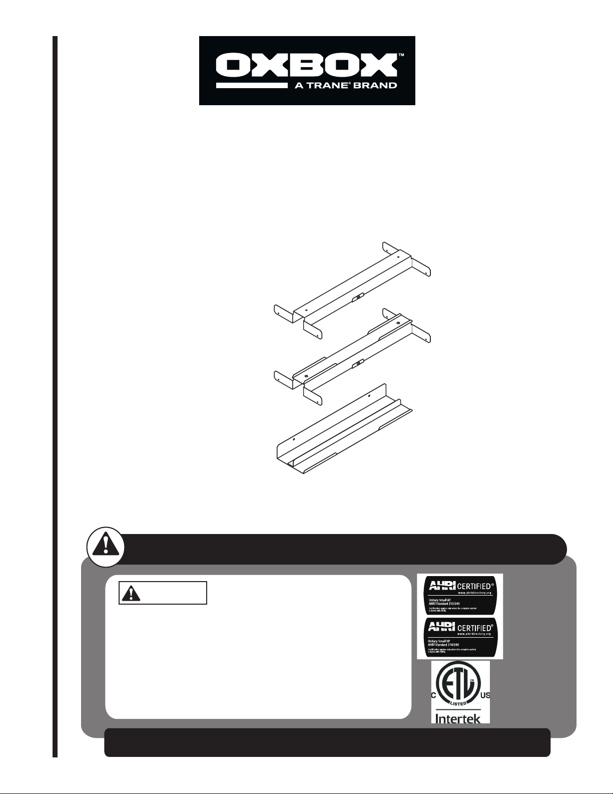
Oxbox 1”-2” Filter Rack Kit
JAYFLTR101A
USED WITH:
Oxbox 2-5 Ton
J4PG4 Gas/Electric Only
BX-SVN-JAYFLTR101-1A-EN
RECOGNIZE THIS SYMBOL AS AN INDICATION OF IMPORTANT SAFETY INFORMATION
WARNING
These instructions are intended as an aid to qualified licensed
service personnel for proper installation, adjustment and
operation of this unit. Read these instructions thoroughly before
attempting installation or operation. Failure to follow these
instruction may result in improper installation, adjustment,
service or maintenance possibly resulting in fire, electrical
shock, property damage, personal injury or death.
DO NOT DESTROY THIS MANUAL
Please read carefully and keep in a safe place for future reference by a serviceman.
Page 2
Installer's Guide
WARNING
s
!
CAUTION
Safety Section
HAZARDOUS VOLTAGE!
Failure to follow this Warning could result in property
damage, severe personal injury, or death.
Disconnect all electric power, including remote disconnects before servicing. Follow proper lockout/tagout
procedures to ensure the power cannot be inadvertently energized.
General Data
!
!
s
SHARP EDGE HAZARD!
Failure to follow this Caution could result in personal
injury.
Be careful of sharp edges on equipment or any cuts
made on sheet metal while installing or servicing.
Personal injury may result.
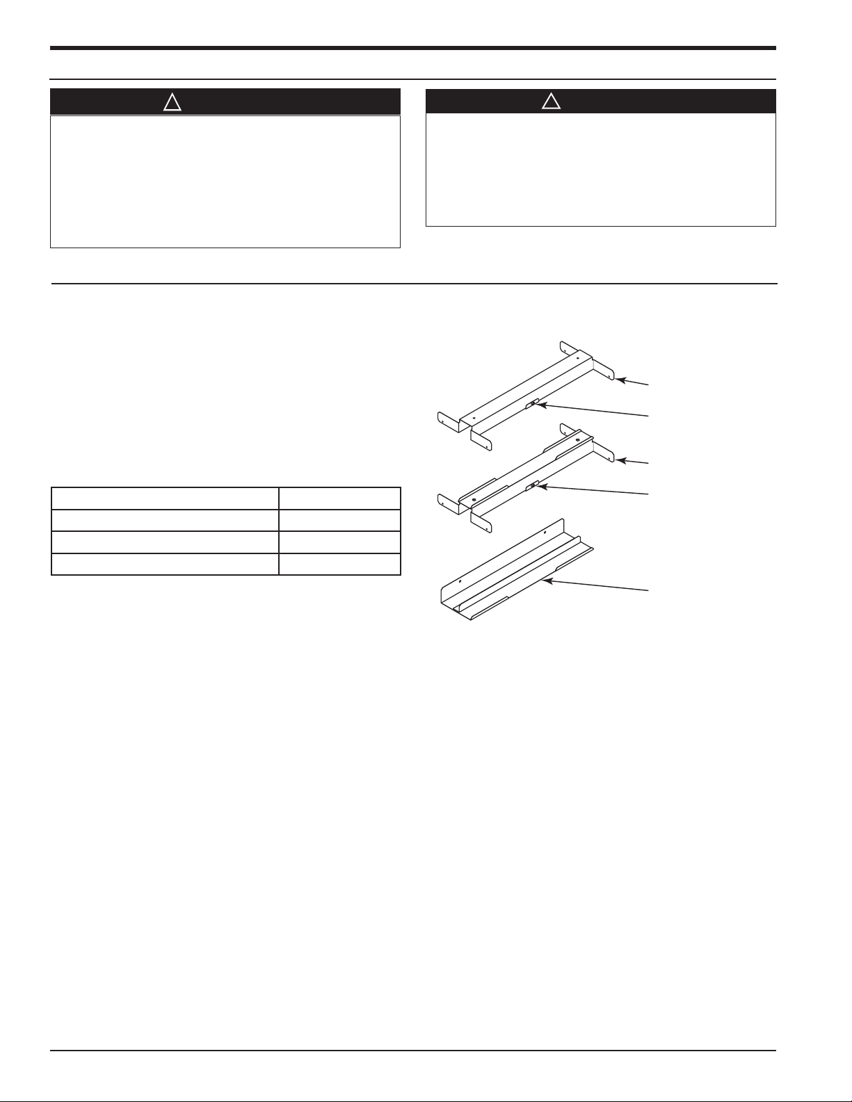
The filter kit is to be field installed inside the packaged
Oxbox unit, and is designed to work with either vertical
or horizontal duct applications. Filters are field provided
and installed. The kit works with either 1” or 2” throw
away filters.
Filters required (not supplied):
• (1) 16” x 20” and (1) 20” x 20” Filter
Kit Contents
Items Quantity
Bottom filter rack 1
Center filter rack 1
Top filter rack 1
Inspection
Check carefully for any shipping damage. This must be
reported to and claims made against the transportation
company immediately. Any missing parts should be
reported to your supplier at once and replaced with
authorized parts only.
Figure 1. Filter Kit Components
Top Filter Rack
Filter Spacer. Remove
when 2” lters used
Center Filter Rack
Filter Spacer. Remove
when 2” lters used
Bottom Filter Rack
2 BX-SVN-JAYFLTR101-1A-EN
Page 3
Installation Instructions
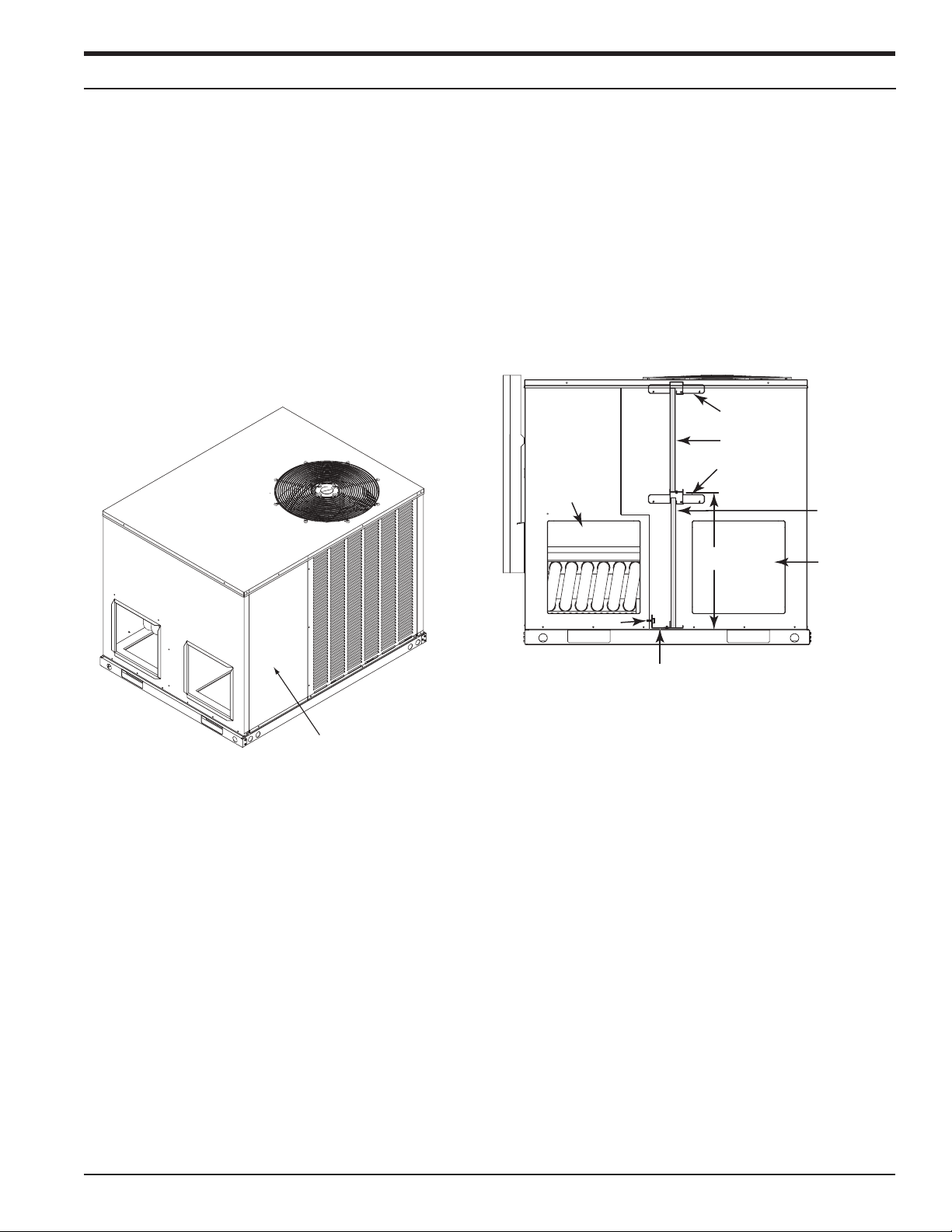
Filter access panel
Bottom Filter Rack
20” x 20” Filter
Installer's Guide
These instructions are organized for an easy step-by
step procedure.
NOTE: These instructions do not purport to cover
all variations in system nor to provide for every
possible contingency to be met in connection with the
installation. Should further information be desired or
should particular problems arise which are not covered
sufficiently for the purchaser’s purposes, the matter
should be referred to the manufacturer.
1. Disconnect all power sources to the Oxbox
packaged unit.
2. Remove the filter access panel. Set panel aside for
later re-installation. See Figure 2.
Figure 2. Panel Removal
5. To make sure the center and top filter rack are
aligned with the bottom rack, use a marker and draw
a vertical line on the unit insulation, starting from
the edge of the bottom rack all the way up to the top
of the unit. Draw this line on both the left and right
sides of the bottom rack. See Figure 3.
6. Measure up 20 ¼” vertically from the bottom rack
to locate the center filter rack. The rack can be held
in place by itself when squeezed in place. Using
screws provided, screw through the pre-punched
holes in the center rack and into the unit on both
sides. See Figure 3.
Figure 3. Filter Rack Locations
Top Filter Rack
16” x 20” Filter
Center Filter
Side supply
air opening
Rack
20-1/4”
Side return
air opening
3. The filter racks fit tightly inside the cabinet. Use care
not to damage unit insulation when installing filter
racks.
4. Place the bottom filter rack into the cabinet and slide
up against the unit panel. The bottom filter rack will
rest directly on the base. Using screws provided,
screw through the pre-punched holes in the back
flange of the filter rack and into unit panel. See
Figure 3.
Screw
7. Install the top filter rack at the very top of the unit,
inline with the bottom and center filter racks. Using
screws provided, screw through pre-punched holes
in the top filter rack and into the unit on both sides.
See figure 3.
8. The screws installed through the top and center
filter racks and through the outside panel of the unit,
are now exposed and sharp. One at a time, these
screws should be removed from the inside of the unit
and reinstalled from the outside of the unit.
NOTE: After the screws have been reinstalled, cover
the screw threads with caulk. This will minimize the
risk of getting injured by one of the screws.
BX-SVN-JAYFLTR101-1A-EN 3
Page 4
Installer's Guide
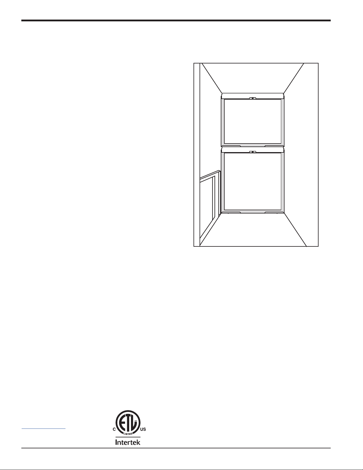
9. Carefully install the field supplied (1) 16” x 20” filter
in the top section and the (1) 20” x 20” filter in the
bottom section. See Figures 3 and 4. Note: if using 2”
filters, remove the filter spacers shown in Figure 1.
NOTE: It is normal for the filter to fit very tightly
against the insulation inside the cabinet.
10. Reinstall the filter access panel that was removed in
step 2.
Figure 4. Front view of the Unit (Filter access panel
removed and lters in place)
TwentyThreeC, LLC
800 Beaty Street,
Davidson, NC 28036
www.oxboxhvac.com
For more information contact
your local dealer (distributor).
4 BX-SVN-JAYFLTR101-1A-EN
Since the manufacturer has a policy of continuous product and product data
improvement, it reserves the right to change the design and specification
without notice.
© 2019 TwentyThreeC, LLC 03/19
 Loading...