

Page 1
INSTALLATION INSTRUCTIONS
95.0% AFUESingle Stage Condensing Gas Furnaces
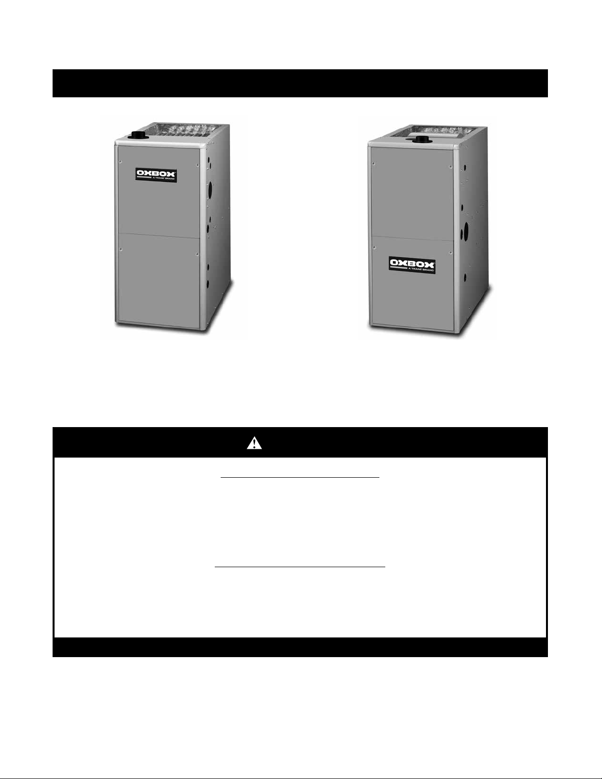
J951X*U (95.0% AFUE)
Upflow / Horizontal Furnace
J951X*D (95.0% AFUE)
Downflow Furnace
WARNING
FIRE OR EXPLOSION HAZARD
• Failure to follow safety warnings exactly could result in serious injury, death or property
damage.
• Installation and service must be performed by a qualified installer, service agency or the gas
supplier.
• Do not store or use gasoline or other flammable vapors and liquids in the vicinity of this or
any other appliance.
WHAT TO DO IF YOU SMELL GAS
• Do not try to light any appliance.
• Do not touch any electrical switch; do not use any phone in your building.
• Leave the building immediately.
• Immediately call your gas supplier from a neighbors phone. Follow the gas suppliers instructions.
• If you cannot reach your gas supplier, call the fire department.
DO NOT DESTROY. PLEASE READ CAREFULLY & KEEP IN A SAFE PLACE FOR FUTURE REFERENCE.
Page 2

TABLE OF CONTENTS
IMPORTANT SAFETY INFORMATION .............................. 3
REQUIREMENTS & CODES .............................................. 3
Combustion Air Quality ..................................................... 4
Heating Load .................................................................... 5
Installation in a Garage .................................................... 5
Clearances to Combustible Materials ............................... 5
Operation of Furnace During Construction ....................... 5
COMBUSTION AIR & VENTING REQUIREMENTS .......... 6
Direct Vent Furnaces ........................................................ 7
Conventional Vent Systems - Confined Spaces ............... 7
Air From Inside ............................................................. 7
Outdoor Air from a Crawl Space or Vented Attic .......... 8
Outdoor Air Using Vertical Ducts .................................. 8
Outdoor Air Using Horizontal Ducts ............................. 8
Air Directly Through An Exterior Wall ........................... 9
Alternate Method of Providing Air from Outside ........... 9
Conventional Vent Systems - Unconfined Spaces ........... 9
Category IV Venting ......................................................... 9
Vent Pipe Material ........................................................ 10
Vent Pipe Length & Diameter ....................................... 10
Vent Pipe Installation .................................................... 10
Outdoor Terminations - Horizontal Venting .................. 11
Outdoor Terminations - Vertical Venting ...................... 12
Vent Freezing Protection .............................................. 12
Existing Installations ..................................................... 12
Condensate Disposal ....................................................... 12
CIRCULATING AIR REQUIREMENTS ............................... 13
Plenums & Air Ducts ........................................................ 13
Return Air Connections .................................................... 13
Upflow & Horizontal Furnaces ...................................... 13
Downflow Furnaces ...................................................... 14
Supply Air Connections .................................................... 14
Acoustical Treatments ...................................................... 14
FURNACE INSTALLATION ................................................ 14
General Requirements ..................................................... 14
Upflow Furnaces .............................................................. 14
Horizontal Furnaces ......................................................... 14
Downflow Furnaces .......................................................... 15
Installation on a Concrete Slab .................................... 15
Inducer & Venting Options ............................................... 15
Inducer Assembly Rotation .......................................... 16
Pressure Switch Tubing ............................................... 16
Alternate Pressure Switch Location ............................. 17
Accessories ...................................................................... 17
Finish Flange ................................................................ 17
Rubber Grommets ........................................................ 17
PVC Components ......................................................... 18
Typical Orientation ................................................... 18
Alternate Orientation ................................................ 18
Optional PVC Pipe Installation ..................................... 18
Condensate Drain Lines ............................................... 18
Bottom Panel Removal ..................................................... 19
Alternate Bottom Panel Removal ..................................... 19
GAS SUPPLY & PIPING ..................................................... 20
Leak Check ...................................................................... 20
High Altitude Application (Natural Gas Only) ................... 20
Converting from Natural Gas to LP / Propane .................. 22
ELECTRICAL WIRING ....................................................... 23
Line Voltage Wiring .......................................................... 23
Grounding ......................................................................... 23
Thermostat / Low Voltage Connections ........................... 24
Twinning ........................................................................... 24
One stage heating ........................................................ 24
Two stage heating ........................................................ 25
Heat Anticipator ................................................................ 25
START-UP & ADJUSTMENTS ........................................... 25
Pre-Start Check List ......................................................... 25
Start-up Procedures ......................................................... 25
Verifying & Adjusting Input Rate ....................................... 25
Verifying & Adjusting Temperature Rise .......................... 26
Verifying Burner Operation ............................................... 26
Verifying Operation of the Supply Air Limit Switch ........... 26
System Operation ............................................................. 26
(Gas) Heating Mode ..................................................... 26
Cooling Mode ............................................................... 26
Manual Fan .................................................................. 26
Fault Conditions ............................................................... 27
OPERATING SEQUENCE .................................................. 27
Heating Cycle ................................................................... 27
Cooling Cycle ................................................................... 27
Fan Mode ......................................................................... 27
MAINTENANCE .................................................................. 27
FIGURES & TABLES .......................................................... 29
Figure 29. J951X*U Cabinet Dimensions ..................... 29
Figure 30. J951X*D Cabinet Dimensions ..................... 29
Figure 31. Wiring Diagram ........................................... 30
Figure 32. Ladder Diagram .......................................... 31
Table 6. Gas Flow Rates .............................................. 32
Table 7. Gas Pipe Capacities ....................................... 32
Table 8. High Altitude Deration – Propane Gas ........... 33
Table 9. Natural Gas Heating Values ........................... 33
Table 10. High Altitude Deration – Natural Gas with
HIGH Heating Value .................................... 34
Table 11. High Altitude Deration – Natural Gas with
LOW Heating Value ..................................... 34
Table 12. Vent Termination Clearances ....................... 35
Figure 33. Horizontal & Vertical Venting ...................... 36
Figure 34. Venting Options for Upflow Installations
(J951X*U Series) ........................................ 37
Figure 35. Venting Options for Horizontal Installations
(J951X*U Series) ........................................ 38
Figure 36. Venting Options for Downflow Installations
(J951X*D Series) ........................................ 39
TROUBLESHOOTING ........................................................ 40
Table 13. Control Board Fault Conditions .................... 40
FURNACE COMPONENTS ................................................ 40
Table 14. Motor Control Board Fault Conditions .......... 40
Figure 37. J951X*U Component Locations .................. 41
Figure 38. J951X*D Component Locations .................. 41
INSTALLATION CHECKLIST ............................................. 44
2
Page 3
IMPORTANT SAFETY INFORMATION
INSTALLER: Please read all instructions before servicing
this equipment. Pay attention to all safety warnings and
any other special notes highlighted in the manual. Safety
markings are used frequently throughout this manual to
designate a degree or level of seriousness and should not
be ignored.
situation that if not avoided, could result in personal injury or
death.
that if not avoided, may result in minor or moderate injury or
property damage.
WARNING - Indicates a potentially hazardous
CAUTION - Indicates a potentially hazardous situation
kerosene, cigarette lighter fluid, dry cleaning fluids, paint
thinners, or other volatile fluids.
• The installer should become familiar with the units wiring
diagram before making any electrical connections to the
unit. See
the unit wiring label.
• Always reinstall the doors on the furnace after
servicing. Do not operate the furnace without all doors
and covers in place.
Figure 32 (page 31), Figure 33 (page 36) or
REQUIREMENTS & CODES
WARNING:
The safety information listed in this manual must
be followed during the installation, service, and
operation of this unit. Unqualified individuals
should not attempt to interpret these instructions
or install this equipment. Failure to follow safety
recommendations could result in possible
damage to the equipment, serious personal
injury or death.
WARNING:
Improper installation, service, adjustment, or
maintenance may cause explosion, fire, electrical
shock or other hazardous conditions which may
result in personal injury or property damage.
Unless otherwise noted in these instructions,
only factory authorized kits or accessories may
be used with this product.
WARNING:
Do not install this furnace if any part has been
submerged under water. A flood damaged furnace
is extremely dangerous. Attempts to use the
furnace may result in fire or explosion. A qualified
service agency should be contacted to inspect the
furnace and to replace any electrical or control
system parts that have been wet or under water.
• To minimize equipment failure or personal injury, it is
essential that only qualified individuals install, service, or
maintain this equipment. If you do not posses mechanical
skills or tools, call your local dealer for assistance.
• Follow all precautions in the literature, on tags, and on
labels provided with the equipment. Read and thoroughly
understand the instructions provided with the equipment
prior to performing the installation and operational
checkout of the equipment.
• Use caution when handling this appliance or removing
components. Personal injury can occur from sharp metal
edges present in all sheet metal constructed equipment.
• Do not store any of the following on, or in contact with,
the unit: Rags, brooms, vacuum cleaners, or other
cleaning tools, spray or aerosol cans, soap powders,
bleaches, waxes, cleaning compounds, plastics or plastic
containers, paper bags or other paper products, gasoline,
WARNING:
The information listed below must be followed
during the installation, service, and operation
of this furnace. Failure to follow safety
recommendations could result in possible
damage to the equipment, serious personal
injury or death.
• This furnace must be installed in accordance with these
instructions, all applicable local building codes and the
current revision of the National Fuel Gas Code (NFPA54/
ANSI Z223.1) or the Natural Gas and Propane Installation
Code, CAN/CSA B149.1.
• Use only with type of gas approved for this furnace. Refer
to the furnace rating plate.
• Install this furnace only in a location and position as
specified on
• Provide adequate combustion and ventilation air to the
furnace space as specified on
page 8
• Provide adequate clearances around the vent air intake
terminal as shown in
, Figure 9 (page 12), & Figure 10 (page 12).
11)
• Combustion products must be discharged outdoors.
Connect this furnace to an approved vent system only,
as specified on
.
12
• Never test for gas leaks with an open flame. Use
a commercially available soap solution to check all
connections. See
• This furnace is designed to operate with a maximum
external pressure rise of 0.5 inches of water column.
Consult the rating plate for the proper circulating air flow
and temperature rise. It is important that the duct system
be designed to provide the correct flow rates and external
pressure rise. An improperly designed duct system can
result in nuisance shutdowns, and comfort or noise
issues.
• When supply ducts carry air circulated by the furnace
to areas outside the space containing the furnace, the
return air shall also be handled by duct(s) sealed to the
furnace casing and terminating in the conditioned space.
See
page 13 .
• A gas-fired furnace for installation in a residential garage
must be installed as specified on
• This furnace is not approved for installation in mobile
homes. Installing this furnace in a mobile home could
cause fire, property damage, and/or personal injury.
• The Commonwealth of Massachusetts requires
compliance with regulation 248 CMR 4.00 and 5.00 for
installation of through – the – wall vented gas appliances
as follows:
page 5.
page 6, page 7,
& page 9.
Figure 7 (page 11), Figure 8 (page
page 9, page 10, page 11, & page
page 20.
page 5.
3
Page 4
1. For direct-vent appliances, mechanical-vent heating
appliances or domestic hot water equipment, where the
bottom of the vent terminal and the air intake is installed
below four feet above grade the following requirements
must be satisfied:
a.) A carbon monoxide (CO) detector and alarm shall be
placed on each floor level where there are bedrooms.
The detector shall comply with NFPA 720 (2005
Edition) and be mounted in the living area outside
the bedroom(s).
b.) A (CO) detector shall be located in the room that
houses the appliance or equipment and shall:
• Be powered by the same electrical circuit as the
appliance or equipment. Only one service switch
shall power the appliance and the (CO) detector;
• Have battery back-up power;
• Meet ANSI/UL 2034 Standards and comply with
NFPA 720 (2005 Edition); and Approved and listed
by a Nationally Recognized Testing Laboratory as
recognized under 527 CMR.
c.) A Product-approved vent terminal must be used,
and if applicable, a product-approved air intake must
be used. Installation shall be in strict compliance
with the manufacturer’s instructions. A copy of the
installation instructions shall remain with the appliance
or equipment at the completion of the installation.
d.) A metal or plastic identification plate shall be mounted
at the exterior of the building, four feet directly above
the location of vent terminal. The plate shall be of
sufficient size, easily read from a distance of eight
feet away, and read “Gas Vent Directly Below”.
2. For direct-vent appliances, mechanical-vent heating
appliances or domestic hot water equipment where the
bottom of the vent terminal and the air intake is installed
above four feet above grade the following requirements
must be satisfied:
a.) A (CO) detector and alarm shall be placed on each
floor level where there are bedrooms. The detector
shall comply with NFPA 720 (2005 Edition) and be
mounted in the living area outside the bedroom(s).
b.) The (CO) detector shall:
• Be located in the room that houses the appliance
or equipment;
• Be hard-wired or battery powered or both.
• Shall comply with NFPA 720 (2005 Edition).
c.) A product-approved vent terminal must be used,
and if applicable, a product-approved air intake must
be used. Installation shall be in strict compliance
with the manufacturer’s instructions. A copy of the
installation instructions shall remain with the appliance
or equipment at the completion of the installation.
The information listed below is for reference purposes only
and does not necessarily have jurisdiction over local or state
codes. Always consult with local authorities before installing
any gas appliance.
Combustion & Ventilation Air
• US: National Fuel Gas Code (NFGC), Air for Combustion and
Ventilation
• CANADA: Natural Gas and Propane Installation Codes
(NSCNGPIC), Venting Systems and Air Supply for Appliances
Duct Systems
• US and CANADA: Air Conditioning Contractors Association
(ACCA) Manual D, Sheet Metal and Air Conditioning
Contractors National Association (SMACNA), or American
Society of Heating, Refrigeration, and Air Conditioning
Engineers (ASHRAE) Fundamentals Handbook
Electrical Connections
• US: National Electrical Code (NEC) ANSI/NFPA 70
• CANADA: Canadian Electrical Code CSA C22.1
Gas Piping & Gas Pipe Pressure Testing
• US: NFGC and National Plumbing Codes
• CANADA: NSCNGPIC
General Installation
• US: Current edition of the NFGC and the NFPA 90B. For
copies, contact the National Fire Protection Association Inc.,
Batterymarch Park, Quincy, MA 02269; or American Gas
Association, 400 N. Capitol, N.W., Washington DC 20001 or
www.NFPA.org
• CANADA: NSCNGPIC. For a copy, contact Standard Sales,
CSA International, 178 Rexdale Boulevard, Etobicoke
(Toronto), Ontario, M9W 1R3 Canada
Safety
• US: (NFGC) NFPA 54–1999/ANSI Z223.1 and the Installation
Standards, Warm Air Heating and Air Conditioning Systems
ANSI/NFPA 90B.
• CANADA: CAN/CSA-B149.1 and .2–M00 National Standard
of Canada. (NSCNGPIC)
Combustion Air Quality
CAUTION:
Combustion air must not be drawn from a
corrosive atmosphere.
To maximize heat exchanger life, the combustion air must be
free of chemicals that can form corrosive acidic compounds
in the combustion gases. The recommended source of
combustion air is to use outdoor air. However, the use of
indoor air in most applications is acceptable except as listed:
• If the furnace is installed as a single pipe installation
in a confined space, it is required that the necessary
combustion air come from the outdoors by way of attic,
crawl space, air duct, or direct opening. For Installations
in confined spaces, see
requirements.
• Installations in these locations may require outdoor air for
combustion, due to chemical exposures:
Commercial buildings
Buildings with indoor pools
Furnaces installed in laundry rooms
Furnaces installed in hobby or craft rooms
Furnaces installed near chemical storage areas
page 7 for combustion air
4
Page 5
UPFLOW
DOWNFLOW
• Exposure to the following substances in the combustion
air supply may require outdoor air for combustion:
Permanent wave solutions
Chlorinated waxes and cleaners
Chlorine based swimming pool chemicals
Water softening chemicals
De-icing salts or chemicals
Carbon Tetrachloride
Halogen type refrigerants
Cleaning solvents (perchloroethylene)
Printing inks, paint removers, varnishes, etc.
Hydrochloric Acid
Cements and glues
Antistatic fabric softeners
Masonry acid washing materials
Heating Load
This furnace should be sized to provide the design heating
load requirement. Heating load estimates can be made
using approved methods available from Air Conditioning
Contractors of America (Manual J); American Society of
Heating, Refrigerating, and Air Conditioning Engineers; or
other approved engineering methods. Excessive oversizing
of the furnace could cause the furnace and/or vent to
fail prematurely.
The ductwork should be appropriately sized to the capacity of
the furnace to ensure its proper airflow rating. For installations
above 2,000 ft., the furnace should have a sea level input
rating large enough that it will meet the heating load after
deration for altitude.
Installation in a Garage
WARNING:
Do not place combustible material on or against
the furnace cabinet or within 6 inches of the
vent pipe. Do not place combustible materials,
including gasoline or any other flammable vapors
and liquids, in the vicinity of the furnace.
This gas-fired furnace may be installed in a residential garage
with the provision that the burners and igniter are located no
less than 18 inches (457mm) above the floor. The furnace
must be located or protected to prevent physical damage
by vehicles.
Clearances to Combustible Materials
This furnace is Design Certified in the U.S. and Canada
by CSA International or Underwriter’s Laboratories for the
minimum clearances to combustible materials. NOTE:
The furnace is listed for installation on combustible or noncombustible flooring. However, wood is the only combustible
flooring allowed for installation. Downflow models must use
the appropriate subase kit when installing over a wood floor.
To obtain model number and specific clearance information,
refer to the furnace rating plate, located inside of the furnace
cabinet.
Access for positioning and servicing the unit must be
considered when locating unit. The need to provide clearance
for access to panels or doors may require clearance distances
over and above the requirements. Allow 24 inches minimum
clearance from the front of the unit. However 36 inches
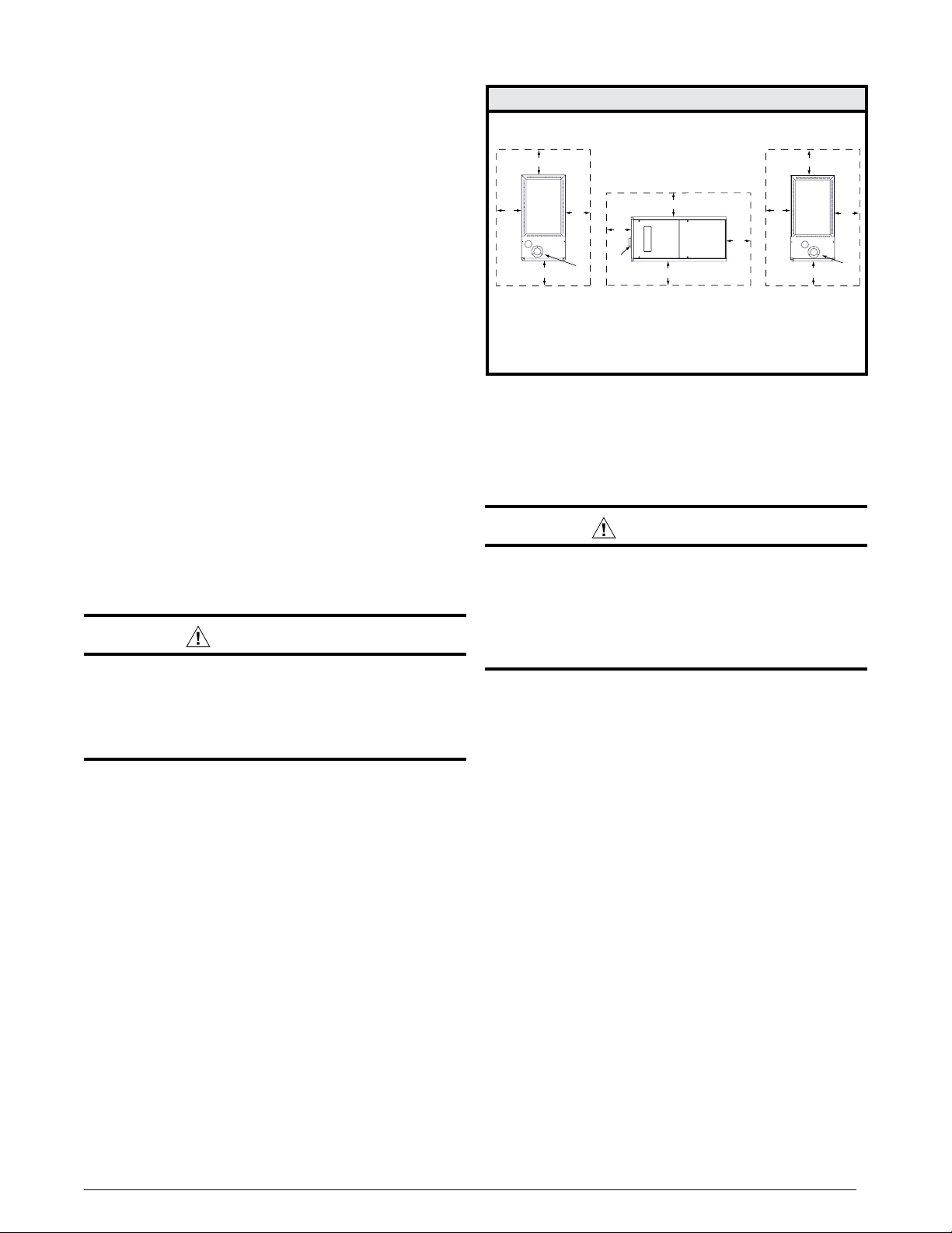
is strongly recommended. See
clearance requirements.
Figure 1 for minimum
CLEARANCES TO COMBUSTIBLE MATERIALS
BOTTOM
APPLICATIONS
BACK
TOP
LEFT SIDE
FRONT
†
4 Inches
RIGHT SIDE
VENT
APPLICATIONS
BACK
TOP
LEFT SIDE
FRONT
Left Side..................0 Inches To p .......................... 0 Inches
Right Side ...............0 Inches Front ......................
Vent ......................... 0 Inches Back ........................0 Inches
†Allow 24 in. minimum clearance for servicing. Recommended clearance
is 36 in.
RIGHT SIDE
VENT
HORIZONTAL
APPLICATIONS
TOP
VENT
SIDE
FRONT
SIDE
Figure 1. Minimum Clearances to
Combustible Materials
Operation of Furnace During Construction
CAUTION:
Failure to follow these instructions will void the
factory warranty and may significantly reduce
the life or the performance of the furnace, and/
or result in other unsafe conditions. It is the
responsibility of the installing contractor to insure
these provisions are met.
Operating gas furnaces in construction environments can
cause a variety of problems with the furnace. Proper use
of commercial portable space heating equipment during
construction is recommended. This gas furnace may be
used during construction if it is not in violation of any
applicable codes and the following criteria are met:
• The installation must meet all applicable codes. The furnace
must be permanently installed according to the instructions
supplied with the furnace. This includes the electrical supply,
gas piping, duct work, and venting. The furnace must be
controlled by a room thermostat properly installed according
to the instructions supplied with the furnace and thermostat.
The installation must include a properly installed air filter in
the return air duct, sealed to the furnace with no by-pass air.
The filter must be inspected frequently and replaced when
necessary.
• The furnace input rate and air temperature rise must be
checked and verified to be within the acceptable ranges as
marked on the furnace nameplate.
• Before occupying the structure: The air filter must be replaced
or cleaned, the duct work must be inspected and cleaned of
any construction debris, and the furnace must be cleaned and/
or repaired if found to be dirty, damaged, or malfunctioning in
any way by a qualified HVAC technician. The furnace shall
be inspected and approved by applicable local authority even
if this requires redundant inspections.
• Serial numbers for furnaces used during construction must
be submitted in writing (fax and email also acceptable). This
information will be used to track the long-term affects of the
use during construction on furnaces. Proof of this submittal
5
Page 6
shall be available for the final inspection of the furnace prior
to occupancy.
• This furnace is designed to operate with return air temperatures
in ranges normally found in occupied residences, including
setbacks. Minimum continuous return temperature must not
be below 60° F (15° C). Occasionally a temporary return
temperature of 55° F (12° C) is acceptable. However, operation
with a return temperature below 55° F (12° C) is not allowed.
• The installing contractor and / or builder must:
— Comply with the requirements of this section.
— Complete the attached Use of Furnace During
Construction checklist.
— Email copy of completed Use of Furnace During
Construction checklist to [email protected]
— Leave original completed Use of Furnace During
Construction checklist with furnace.
— Disclose use of the furnace during construction to the
homeowner in advance of the sale.
COMBUSTION AIR & VENTING
REQUIREMENTS
WARNING:
CARBON MONOXIDE POISONING HAZARD
Failure to follow the steps outlined below
for each appliance connected to the venting
system being placed into operation could
result in carbon monoxide poisoning or death.
The following steps shall be followed with
each individual appliance connected to the
venting system being placed in operation,
while all other appliances connected to the
venting system are not in operation:
1. Seal any unused openings in the venting
system.
2. Inspect the venting system for proper size and
horizontal pitch, as required in the National Fuel
Gas Code, ANSI Z223.1/NFPA 54 or the CSA
B149.1, Natural Gas and Propane Installation
Codes and these instructions. Determine that
there is no blockage or restriction, leakage,
corrosion and other deficiencies which could
cause an unsafe condition.
3. As far as practical, close all building doors
and windows and all doors between the space
in which the appliance(s) connected to the
venting system are located and other spaces
of the building.
4. Close fireplace dampers.
5. Turn on clothes dryers and any appliance
not connected to the venting system. Turn on
any exhaust fans, such as range hoods and
bathroom exhausts, so they are operating at
maximum speed. Do not operate a summer
exhaust fan.
6. Follow the lighting instructions. Place the
appliance being inspected into operation.
Adjust the thermostat so appliance is operating
continuously.
7. Test for spillage from draft hood equipped
appliances at the draft hood relief opening
after 5 minutes of main burner operation. Use
the flame of a match or candle.
8. If improper venting is observed during any of
the above tests, the venting system must be
corrected in accordance with the National Fuel
Gas Code, ANSI Z223.1/NFPA 54 and/or CSA
B149.1, Natural Gas and Propane Installation
Codes.
9. After it has been determined that each
appliance connected to the venting system
properly vents when tested as outlined above,
return doors, windows, exhaust fans, fireplace
dampers and any other gas-fired burning
appliance to their previous conditions of use.
6
Page 7
IMPORTANT INFORMATION:
• This furnace must be vented in compliance with
the current revision of the National Fuel Gas Code
(ANSI-Z223.1/NFPA54). Instructions for determining the
adequacy of an installation can be found in the current
revision of the NFGC (ANSI Z223.1 / NFPA54). Refer
to the NFGC for approved vent tables. Consult local
codes for special requirements. These requirements
are for US installations as found in the NFGC.
• Furnace installation using methods other than those
described in the following sections must comply with
the National Fuel Gas Code (NFGC) and all applicable
local codes.
• Requirements in Canada (B149.1) are structured
differently. In Canada, venting shall conform to
the requirements of the current (CAN/CSA B149.1)
installation codes. Consult local codes for special
requirements.
• Provisions must be made during the installation of
this furnace that provide an adequate supply of air
for combustion. The combustion air from the outside
needs to be clear of chemicals that can cause corrosion.
The inlet pipe should not be placed near corrosive
chemicals such as those listed on
page 5.
WARNING:
Upon completion of the furnace installation,
carefully inspect the entire flue system both
inside and outside the furnace to assure it is
properly sealed. Leaks in the flue system can
result in serious personal injury or death due
to exposure of flue products, including carbon
monoxide.
WARNING:
This furnace must not be vented with other
appliances, even if that appliance is of the
condensing type. Common venting can result
in severe corrosion of other appliances or their
venting and can allow combustion gases to
escape through such appliances or vents. Do
not vent the furnace to a fireplace chimney or
building chase.
This condensing furnace is certified for installation either as
a Direct Vent (2-pipe) or Conventional (1-pipe) appliance.
Direct Vent appliances draw combustion air from the outdoors
and vent combustion products back outside. Installation
with air taken from around the furnace is often referred to
as Conventional installation - i.e. only the vent (exhaust)
pipe is provided.
Another important consideration when selecting one or
two pipe installation is the quality of the Indoor air which
can sometimes be contaminated with various household
chemicals . These chemicals can cause severe corrosion
in the furnace combustion system. A 2-pipe installation has
the additional advantage that it isolates the system from the
effects of negative pressure in the house.
CAUTION:
Exhaust fans, clothes dryers, fireplaces and
other appliances that force air from the house
to the outdoors can create a negative pressure
inside the house, resulting in improper furnace
operation or unsafe conditions such as flame roll
out. It is imperative that sufficient air exchange
with the outdoors is provided to prevent
depressurization. Additional information about
how to test for negative pressure problems can
be found in the NFGC.
Air openings on top of the furnace and openings in closet
doors or walls must never be restricted. If the furnace is
operated without adequate air for combustion, the flame rollout switch will open, turning off the gas supply to the burners.
IMPORTANT NOTE
This safety device is a manually reset switch. DO NOT
install jumper wires across these switches to defeat
their function or reset a switch without identifying
and correcting the fault condition. If a switch must be
replaced, use only the correct sized part specified in the
Replacement Parts List provided online.
Direct Vent Furnaces
Direct Vent (2-pipe) furnaces draw combustion air directly from
the outdoors and then vent the combustion products back
outside, isolating the entire system from the indoor space.
It is important to make sure that the whole system is sealed
and clearances to combustibles are maintained regardless
of the installation being in a confined or unconfined space.
Conventional Vent Systems - Confined Spaces
A confined space is an area with volume less than 50 cubic feet
per 1,000 Btuh of the combined input rates of all appliances
drawing combustion air from that space. Furnace closets,
small equipment rooms and garages are confined spaces.
Furnaces installed in a confined space which supply heated
air to areas outside the space must draw return air from
outside the space and must have the return air ducts tightly
sealed to the furnace. Ducts must have cross - sectional
area at least as large as the free area of their respective
openings to the furnace space. Attics or crawl spaces must
connect freely with the outdoors if they are the source of air
for combustion and ventilation.
The required sizing of these openings is determined by
whether inside or outside air is used to support combustion,
the method by which the air is brought to the space, and by
the total input rate of all appliances in the space. In all cases,
the minimum dimension of any combustion air opening is
3 inches.
Air From Inside
If combustion air is taken from the heated space, the two
openings must each have a free area of at least one square
inch per 1,000 Btuh of total input of all appliances in the
confined space, but not less than 100 square inches of free
area. See
Example and Figure 2.
7
Page 8
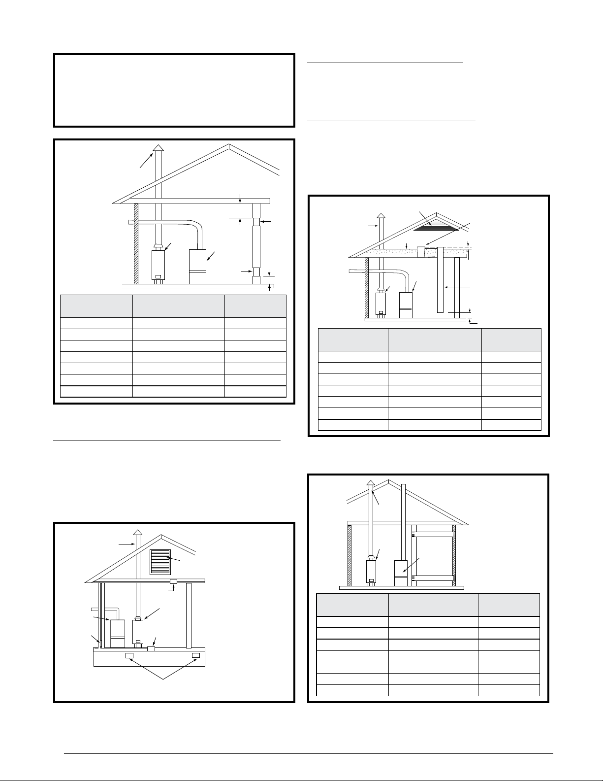
EXAMPLE
Notes
NOTES:
Each opening must be
at least 100 sq. in. or
1 sq. in. per 1,000 Btuh
of total input rating,
whichever is greater.
Openings must start at
no more than 12 inches
from the top and bottom
of the enclosure.
per 4,000 Btuh of
Air Duct must be
per 4,000 Btuh of
Ventilation Louvers
12" Max
Unheated Crawl Space
.
Alter
Air Ducts must be
If the combined input rate of all appliances is less than or
equal to 100,000 Btuh, each opening must have a free
area of at least 100 in
appliances is 120,000 Btuh, each opening must have a
free area of at least 120 in
Vent or
Chimney
2
. If the combined input rate of all
2
.
Outdoor Air Using Vertical Ducts
If combustion air is taken from outdoors through vertical
ducts, the openings and ducts must have a minimum free
area of one square inch per 4,000 Btuh of total appliance
input. See
Figure 4 (page 8).
Outdoor Air Using Horizontal Ducts
If combustion air is taken from outdoors through horizontal
ducts, the openings and ducts must have a minimum free
area of one square inch per 2,000 Btuh of total appliance
input. Ducts must have cross - sectional area at least as
large as the free area of their respective openings to the
furnace space. See
Figure 5.
12” Max.
See
Water
Heater
Furnace
See
TOTAL INPUT
RATING (BTUH)
Notes
MINIMUM FREE AREA
(EACH OPENING)
12” Max.
ROUND DUCT
DIAMETER
40,000 100 sq. In 12 inches
60,000 100 sq. In 12 inches
80,000 100 sq. In 12 inches
100,000 100 sq. In 12 inches
120,000 120 sq. In 13 inches
140,000 140 sq. In 14 inches
160,000 160 sq. In 15 inches
Figure 2. Combustion Air Drawn from Inside
Outdoor Air from a Crawl Space or Vented Attic
When the openings can freely exchange air with the outdoors,
each opening shall have a minimum free area of 1 square
inch per 4,000 Btuh of total appliance input. The openings
shall exchange directly, or by ducts, with the outdoor spaces
(crawl or attic) that freely exchange with the outdoors. See
Figure 3 (page 8).
at each end of attic
Vent or
Chimney
TOTAL INPUT
RATING (BTUH)
40,000 10 sq. In 4 inches
60,000 15 sq. In 5 inches
80,000 20 sq. In 5 inches
100,000 25 sq. In 6 inches
120,000 30 sq. In 6 inches
140,000 35 sq. In 7 inches
160,000 40 sq. In 8 inches
Attic
Insulation
Water
Furnace
Heater
MINIMUM FREE AREA
(EACH OPENING)
at least 1 sq. in.
total input rating.
Ducts must
extend above
attic insulation.
Air Duct must be
at least 1 sq. in.
total input rating.
ROUND DUCT
DIAMETER
Figure 3. Combustion Air Drawn from Outside
Through Vertical Ducts
Vent or
Chimney
8
Vent or
Chimney
Ventilation Louvers
(each end of attic)
Water
Heater
Inlet Air
---------
---------
NOTE: Air openings shall
each have a free area of
not less than one square
inch per 4,000 Btuh of the
total input rating of all
equipment in the enclosure
---------
Outlet
Air
Furnace
nate
Air Inlet
---------
Ventilation Louvers For
Figure 4. Combustion Air Drawn from a Crawl
Space or Vented Attic
Air Duct
Furnace
Air Duct
MINIMUM FREE AREA
(EACH OPENING)
at least 1 sq. in.
per 2,000 Btuh of
total input rating.
ROUND DUCT
DIAMETER
TOTAL INPUT
RATING (BTUH)
Water
Heater
40,000 20 sq. In 5 inches
60,000 30 sq. In 6 inches
80,000 40 sq. In 7 inches
100,000 50 sq. In 8 inches
120,000 60 sq. In 9 inches
140,000 70 sq. In 10 inches
160,000 80 sq. In 10 inches
Figure 5. Combustion Air Drawn from Outside
Through Horizontal Ducts
Page 9
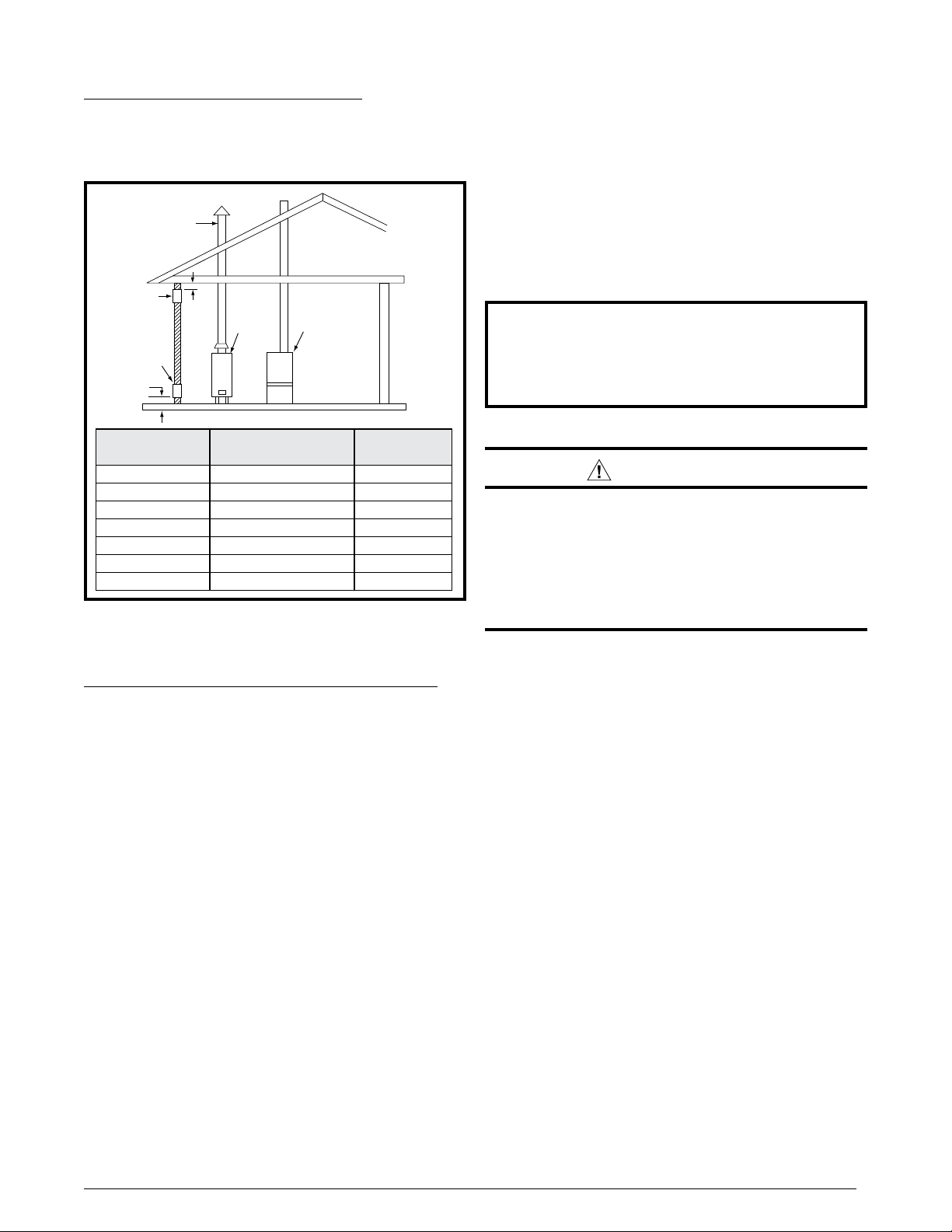
Air Directly Through An Exterior Wall
Each opening to outside
12" Max.
If combustion air is provided directly through an exterior
wall, the two openings must each have free area of at least
one square inch per 4,000 Btuh of total appliance input.
See
Figure 6.
Vent or
Chimney
See
Note
See
Note
-
-
-
-
-
-
-
-
-
Max
-
-
-
-
-
-
-
-
-
12"
Water
Heater
NOTE:
must be at least 1 sq. in. per
4,000 Btuh of total input rating.
Furnace
Conventional Vent Systems - Unconfined
Spaces
An unconfined space is an area including all rooms not
separated by doors with a volume greater than 50 cubic feet
per 1,000 Btuh of the combined input rates of all appliances
which draw combustion air from that space.
In general, a furnace installed in an unconfined space will not
require outside air for combustion. However, in homes built for
energy efficiency (low air change rates), it may be necessary
to provide outside air to ensure adequate combustion and
venting, even though the furnace is located in an unconfined
space. See
A space with a water heater rated at 45,000 Btuh input
and a furnace rated at 75,000 Btuh requires a volume of
6,000 cubic feet [50 x (45 + 75) = 6,000] to be considered
unconfined. If the space has an 8 foot ceiling, the floor
area of the space must be 750 sq. ft. (6,000 / 8 = 750).
Example below.
EXAMPLE
TOTAL INPUT
RATING (BTUH)
40,000 10 sq. In 4 inches
60,000 15 sq. In 5 inches
80,000 20 sq. In 5 inches
100,000 25 sq. In 6 inches
120,000 30 sq. In 6 inches
140,000 35 sq. In 7 inches
160,000 40 sq. In 8 inches
MINIMUM FREE AREA
(EACH OPENING)
ROUND DUCT
DIAMETER
Figure 6. Combustion Air Drawn from Outside
Through an Exterior Wall
Alternate Method of Providing Air from Outside
If acceptable under local Codes, it is permitted to provide
outside air using one opening (See NFGC). Generally,
confined spaces must have two openings in the space for
combustion air. One opening must be within 12 inches of
the ceiling, and the other must be within 12 inches of the
floor. However, an alternative method recently adopted by
the NFGC uses one opening within 12 inches of the top of
the space. This method may be used if it is acceptable to
the local codes.
THE FOLLOWING CONDITIONS MUST BE MET:
1. The opening must start within 12” of the top of the structure
and connect with the out of doors through vertical or
horizontal ducts or be ducted to a crawl or attic space that
connects with the out of doors.
2. The opening must have a minimum free area of 1 sq.
in. per 3,000 Btu per hour of the total input rating of all
equipment located in the enclosure.
3. The free area must not be less than the sum of all the
areas of the vent connectors in the enclosure.
Category IV Venting
WARNING:
Upon completion of the furnace installation,
carefully inspect the entire flue system both
inside and outside the furnace to assure it is
properly sealed. Leaks in the flue system can
result in serious personal injury or death due
to exposure of flue products, including carbon
monoxide.
This furnace is classified as a “Category IV” appliance,
which requires special venting materials and installation
procedures. This section specifies installation requirements
for Conventional (1-pipe) and Direct Vent (2-pipe) piping.
For 1- pipe installations, install vent piping as described in
this section and provide air for combustion and ventilation
according to
The length of vent and combustion air piping for either type
of installation are llisted in
Category IV appliances operate with positive vent pressure
and therefore require vent systems which are thoroughly
sealed. They also produce liquid condensate, which is slightly
acidic and can cause severe corrosion of ordinary venting
materials. Furnace operation can be adversely affected by
restrictive vent and combustion air piping.
The inducer assembly on this furnace can be rotated to
vent the flue products out of the top, left or right side. This
increases the flexibility of which direction the vent pipe can
exit the furnace.
page 6 , page 7, page 8 & page 9 .
Table 1.
9
Page 10
Vent Pipe Material
Vent and combustion air pipe and fittings must be one of
the following materials in the list and must conform to the
indicated ANSI/ASTM standards.
MATERIALS STANDARDS
Schedule 40PVC ......................................................D1785
CPVC ........................................................................D1784
PVC-DWV .................................................................D2665
SDR-21 & SDR-26 ....................................................D2241
ABS-DWV ................................................................. D2661
Schedule 40 ABS .....................................................F628
Foam / Cellular Core PVC ........................................ F891
*PolyPro
*When using PolyPro®, all venting and fittings must be from the same
manufacturer with no interchanging of other materials. Refer to specific
instructions supplied with the PolyPro vent kits
®
by DuraVent ............................................. ULC-S636
When joining PVC to PVC, use cement that conforms to
ASTM standard D2564. PVC primer must meet standard
ASTM F656. When joining ABS to ABS, use cement that
conforms to ASTM standard D2235. When joining PVC
to ABS, use cement as specified in procedure from ASTM
standard D3138
In Canada, all plastic vent pipes and fittings including any
cement, cleaners, or primers must be certified as a system
to ULC S636. However this requirement does not apply to
the finish flanges or piping internal to the furnace.
Vent Pipe Length & Diameter
In order for the furnace to operate properly, the combustion
air and vent piping must not be excessively restrictive.
• The venting system should be designed to have the
minimum number of elbows or turns.
• Transition to the final vent diameter should be done as
close to the furnace outlet as practical.
• Always use the same size or a larger pipe for combustion
air that is used for the exhaust vent.
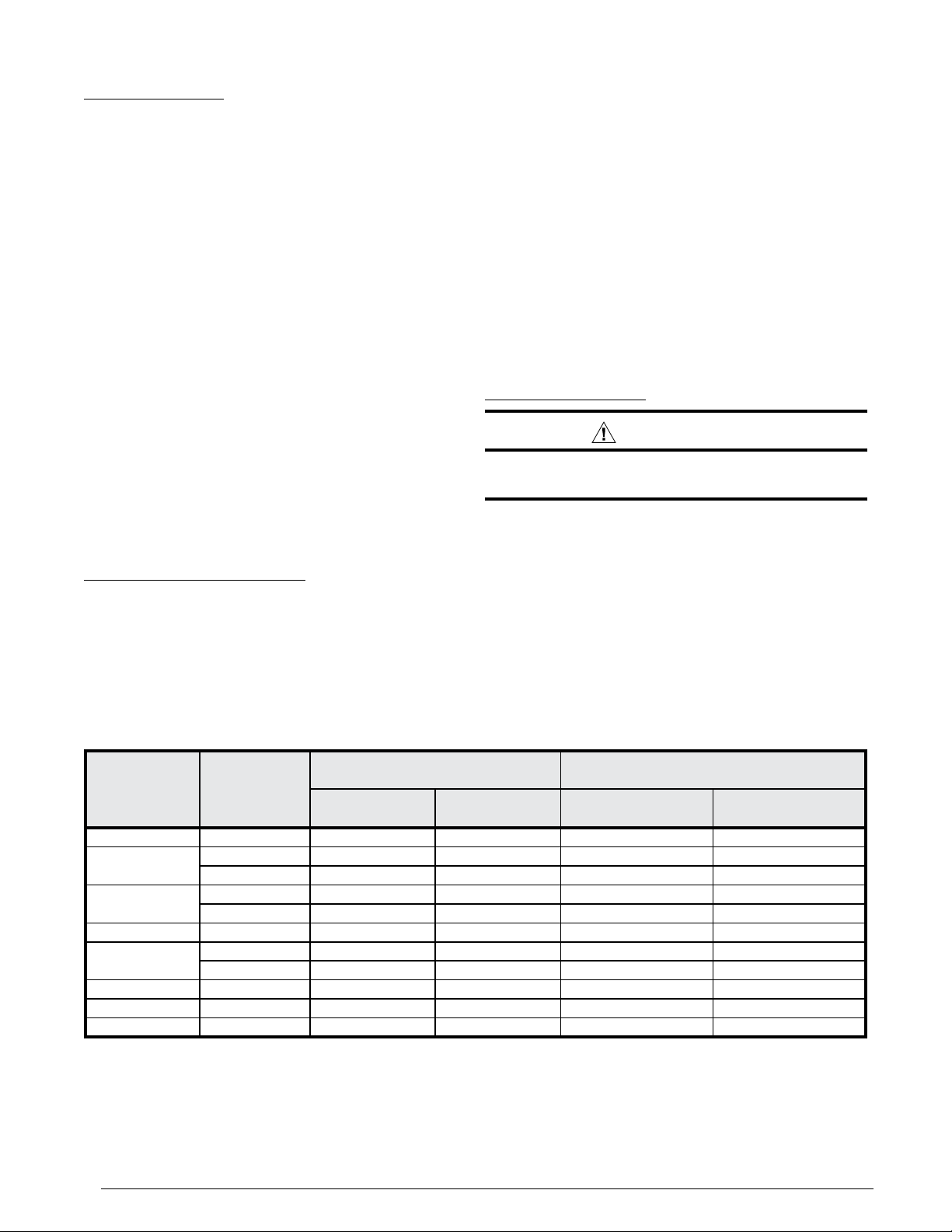
Table 1 (page 10) indicates the maximum allowable pipe
length for a furnace of known input rate, when installed with
piping of selected diameter and number of elbows. To use
the table, the furnace input rate, the centerline length and
the number of elbows on each pipe must be known.
When estimating the length of vent runs, consideration must
be made to the effect of elbows and other fittings. This is
conveniently handled using the idea of “equivalent length”.
This means the fittings are assigned a linear length that
accounts for the pressure drop they will cause. For example:
a 2” diameter, long radius elbow is worth the equivalent of
2.5 feet of linear run. A 90 degree tee is worth 7 ft.
The equivalent lenghts of tees and various elbows are listed
in
Table 1. Measure the linear length of your vent run and
then add in the equivalent length of each fitting. The total
length, including the equivalent fitting lengths, must be less
than the maximum length specified in the table.
Vent Pipe Installation
CAUTION:
Combustion air must not be drawn from a
corrosive atmosphere.
This furnace has been certified for installation with zero
clearance between vent piping and combustible surfaces.
However, it is good practice to allow space for convenience
in installation and service.
• In the absence of local codes, the location of any
combustion air inlet relative to any vent terminal must
be at least 8 inches. This includes installations involving
more than one furnace.
• The quality of outdoor air must also be considered. Be
sure that the combustion air intake is not located near
a source of solvent fumes or other chemicals which can
cause corrosion of the furnace combustion system. (See
page 5 for a sample list of substances).
FURNACE
MODELS
(BTU)
38,000 Upflow 50 70 50 70
54,000
72,000
85,000 Upflow 60 90 60 90
90,000
108,000 Upflow N/A 90 N/A 90
115,000 Upflow N/A 90 N/A 90
120,000 Upflow N/A 90 N/A 90
1. Subtract 2.5 ft. for each additional 2 inch long radius elbow, 5 ft. for each additional 2 inch short radius elbow, 3.5 ft. for each additional 3 inch long radius elbow,
and 7 ft. for each additional 3 inch short radius elbow. Subtract 5 ft for each 2” tee and 8 ft for each 3” tee.
2. Two 45 degree elbows are equivalent to one 90 degree elbow.
3. This table applies for elevations from sea level to 2,000 ft. For higher elevations, decrease pipe lengths by 8% per 1,000 ft of altitude.
4. A long radius elbow’s centerline radius is equal to or greater than 1.5 times the vent diameter.
FURNACE
INSTALLATION
Upflow 70 90 70 90
Downflow 70 90 70 90
Upflow 50 90 50 90
Downflow 50 90 50 90
Upflow 60 90 60 90
Downflow 60 90 60 90
SINGLE VENT PIPE LENGTH (FT.)
WITH 1 LONG RADIUS ELBOW†
OUTLET
2” DIAMETER
OUTLET
3” DIAMETER
†
NOTES:
DUAL VENT PIPE LENGTH (FT.)
WITH 1 LONG RADIUS ELBOW ON EACH PIPE†
INLET / OUTLET
2” DIAMETER
INLET / OUTLET
3” DIAMETER
Table 1. Vent Pipe Lengths
10
Page 11
• Route piping as direct as possible between the furnace
12” min. to maximum
expected snow level
(both pipes)
90° Elbow
Exhaust vent
option B
Exhaust vent
option A
Mounting kit faceplate
secured to wall with screws
(both pipes)
Combustion
air inlet
Exhaust vent
option C
18” Min.
36” Max.
8” Min.
36” Max.
(all positions)
Note 2
Mechanical draft
vent terminal
Direct vent
terminal
50,000 Btuh
or less
Forced air inlet
Direct vent
terminal - more
than 50,000 Btuh
Mechanical
draft vent
terminal
Mechanical
draft vent
terminal
Less
than
10 ft.
3 ft.
NOTES:
1. All dimensions shown are
minimum requirements.
2. Exterior vent terminations must
be located at least 12” above the
maximum expected snow level.
Note 2
4 ft
4 ft
12 in.
12 in.
9 in.
Note 2
and the outdoors. Horizontal piping from inducer to
the flue pipe must be sloped 1/4” per foot to ensure
condensate flows towards the drain tee or PVC trap.
Longer vent runs require larger pipe diameters. Refer to
the Inducer & Venting Options section on
page 15 for
additional information.
• If a Direct Vent (2-pipe) system is used, the combustion
air intake and the vent exhaust must be located in the
same atmospheric pressure zone. This means both pipes
must exit the building through the same portion of exterior
wall or roof as shown in
Figure 33 (page 36).
• Piping must be mechanically supported so that its weight
does not bear on the furnace. Pipe supports must be
installed a minimum of every five feet along the vent run
to ensure no displacement after installation. Supports
may be at shorter intervals if necessary to ensure that
there are no sagging sections that can trap condensate.
It is recommended to install couplings along the vent
pipe, on either side of the exterior wall (
Figure 33). These
couplings may be required by local code.
• If breakable connections are required in the combustion
air inlet pipe (if present) and exhaust vent piping, then
straight neoprene couplings for 2” or 3” piping with hose
clamps can be used. These couplings can be ordered
through your local furnace distributor. To install a
coupling:
1. Slide the rubber coupling over the end of the pipe that is
attached to the furnace and secure it with one of the hose
clamps.
2. Slide the other end of the rubber coupling onto the other
pipe from the vent.
3. Secure the coupling with the second hose clamp, ensuring
that the connection is tight and leak free.
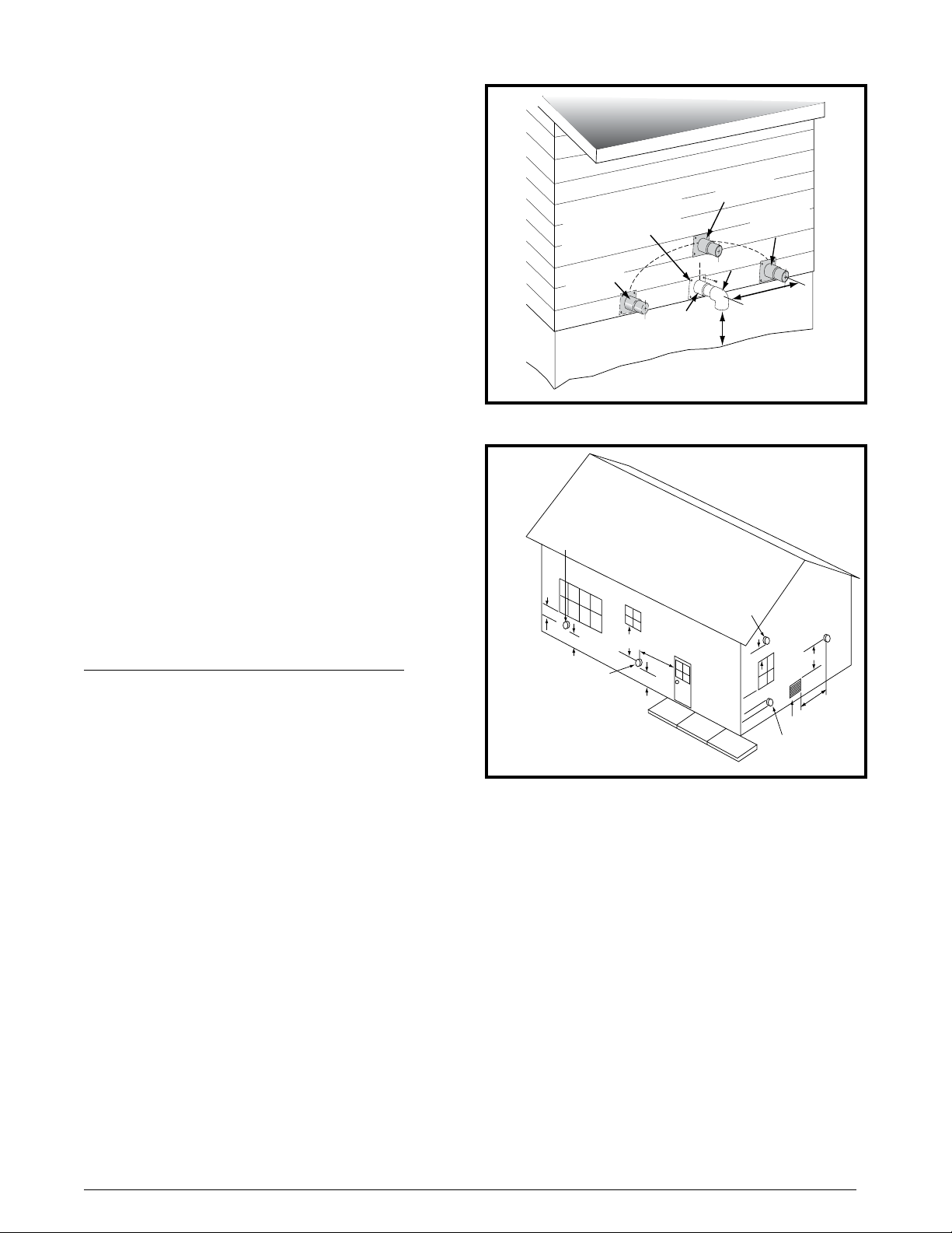
Figure 7. Inlet & Exhaust Pipe Clearances
Outdoor Terminations - Horizontal Venting
• Vent and combustion air intake terminations shall be
installed as shown in
with these instructions:
• Vent termination clearances must be consistent with the
NFGC, ANSI 2223.1/NFPA 54 and/or the CSA B149.1,
Natural Gas and Propane Installation Code.
(page 35)
termination to windows and building air intakes.
• Vent and combustion air intake terminations must
be located to ensure proper furnace operation and
conformance to applicable codes. A vent terminal must
be located at least 3 feet above any forced air inlet located
within 10 feet. This does not apply to the combustion air
inlet of a direct vent (two pipe) appliance. In Canada,
CSA B149.1 takes precedence over these instructions.
See
Table 12.
• All minimum clearances must be maintained to protect
building materials from degradation by flue gases. See
(
Figure 8).
• For optimal performance, vent the furnace through a wall
that experiences the least exposure to winter winds.
• The vent termination shall be located at least 3 ft.
horizontally from any electric meter, gas meter, regulator
and any relief equipment. These distances apply ONLY
to U.S. installations. In Canada, CSA B149.1 takes
precedence over these instructions.
Figure 7 & Figure 8 and in accordance
Table 12
lists the necessary distances from the vent
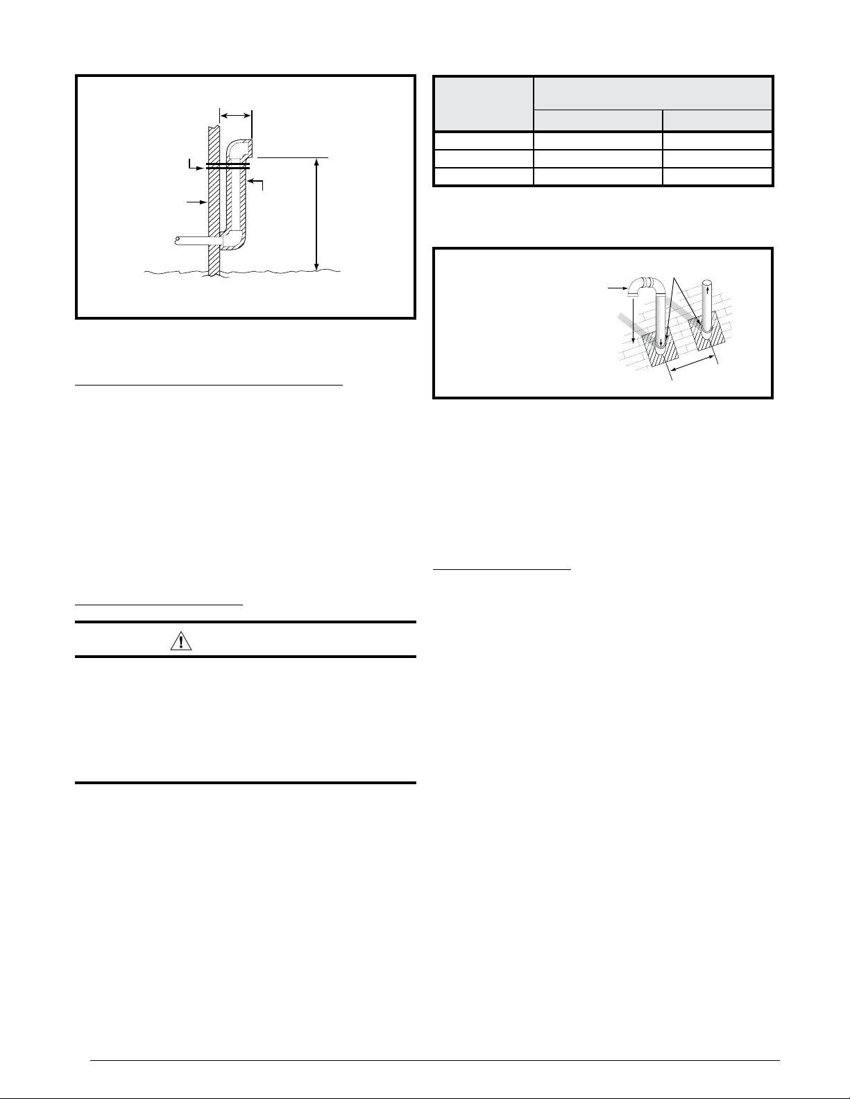
Figure 8. Vent Locations
• Do not install the vent terminal such that exhaust is
directed into window wells, stairwells, under decks or into
alcoves or similar recessed areas, and do not terminate
above any public walkways.
• If venting horizontally, a side wall vent kit is available
according to the pipe diameter size of the installation. 2
inch and 3 inch kits are available. Refer to the technical
sales literature for part numbers. Please follow the
instructions provided with the kit.
• Concentric vent termination kits are available for use with
these furnaces. Refer to the technical sales literature for
kit numbers.
• When the vent pipe must exit an exterior wall close to
the grade or expected snow level where it is not possible
to obtain clearances shown in
provided as shown in
Figure 9 (page 12). Insulation is
Figure 7, a riser may be
required to prevent freezing of this section of pipe. See
Table 3 (page 15) for vent freezing protection.
11
Page 12
Support
NOTE: Vent Configuration to Provide
12" Minimum height above Snow Level.
1/2"
Armaflex
Insulation or
Equivalent
(if required)
12" Above
Maximum
Expected
Snow Level
19" Max.
(See Note)
Outside
Wall
inlet must be positioned pointing
Plumbing Vent Roof Boot
WINTER DESIGN
TEMPERATURE
20 45 70
0 20 70
-20 10 60
*NOTE: Insulation thickness greater than 3/8 inch, based on an R value
of 3.5 (ft x F x hr) / (BTU x in.)
MAXIMUM FLUE PIPE LENGTH (FEET)
IN UNCONDITIONED & EXTERIOR SPACES
WITHOUT INSULATION WITH INSULATION*
Table 2. Vent Protection
Figure 9. Alternate Horizontal Vent Installation
Outdoor Terminations - Vertical Venting
Termination spacing requirements from the roof and from
each other are shown in
be properly flashed and waterproofed with a plumbing roof
boot or equivalent flashing. Vent and combustion air piping
may be installed in an existing chimney which is not in use
provided that:
• Both the exhaust vent and air intake run the length of the
chimney.
• The top of the chimney is sealed and weatherproofed.
• The termination clearances shown in
maintained.
• No other gas fired or fuel-burning equipment is vented
through the chimney.
Vent Freezing Protection
When the vent pipe is exposed to temperatures
below freezing (i.e., when it passes through
unheated spaces, chimneys, etc.) the pipe
must be insulated with 1/2 inch thick sponge
rubber insulation, Armaflex-type insulation or
equivalent. Insulating pipe is important to avoid
condensate icing.
• Table 2 lists the maximum length of flue pipe that can
travel through an unconditioned space or an exterior
space. The total vent length must not exceed the lengths
noted in
please refer to the Canadian Installation Code (CAN/
CSA-B149.1 or 2) and/or local codes.
• For extremely cold climates or for conditions of short
furnace cycles (i.e. set back thermostat conditions)
the last 18 inches of vent pipe can be reduced. It is
acceptable to reduce from 3” to 2-1/2”, 3” to 2”, or 2” to
1-1/2” if the total vent length is at least 15 feet in length,
and the vent length is within the parameters specified in
Table 1. The restriction should be counted as 3 equivalent
feet. Smaller vent pipes are less susceptible to freezing,
but must not be excessively restrictive. The length of the
2 inch pipe must not be longer than 18 inches.
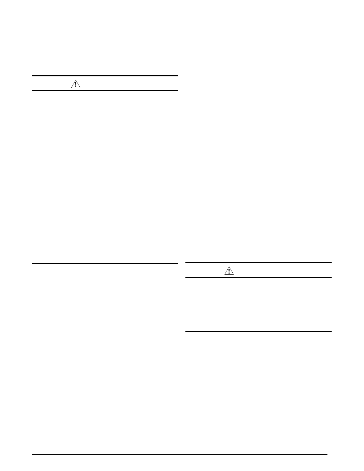
Figure 10. The roof penetration must
Figure 10 are
CAUTION:
Table 1 (page 10). For Canadian installations,
Elbows on the combustion air
away from the exhaust vent.
12” Above Maximum
Expected Snow Level
(Both pipes)
(Both Pipes)
Combustion Air
8" Min.
36" Max.
Exhaust Vent
Figure 10. Vertical Vent Termination
• If furnace is installed horiziontally, make sure the drainage
port on the in-line drain assembly is pointed downward
to ensure proper drainage of condensate. For J951X*U
series, see
Figure 35 (page 38).
• To prevent debris or creatures from entering the
combustion system, a protective screen may be installed
over the combustion air intake opening. The screens hole
size must be large enough to prevent air restriction.
Existing Installations
When an existing furnace is removed from a vent system
serving other appliances, the existing vent system may not be
sized properly to vent the remaining appliances (For example:
water heater). An improperly sized venting system can result
in the formation of condensate, leakage, or spillage. The
existing vent system should be checked to make sure it is in
compliance with NFGC and must be brought into compliance
before installing the furnace.
NOTE: If replacing an existing furnace, it is possible you will
encounter an existing plastic venting system that is subject
to a Consumer Product Safety Commission recall. The pipes
involved in the recall are High Temperature Plastic Vent
(HTPV). If your venting system contains these pipes DO
NOT reuse this venting system! This recall does not apply
to other plastic vent pipes, such as white PVC or CPVC.
Check for details on the CPSC website or call their toll-free
number (800) 758-3688.
Condensate Disposal
The method for disposing of condensate varies according
to local codes. Consult your local code or authority having
jurisdiction. Neutralizer kit is available for use with this furnace.
Refer to the technical sales literature for part numbers. Please
follow the instructions provided with the kit.
This furnace has multiple options for positioning the vent
pipe as described in the, Vent and Inducer Assembly Options
section (
be J-trapped using field supplied parts. After the condensate
lines are J-trapped, they may be combined together when
routed to the drain.
page 15). Each of the condensate drain lines must
12
Page 13
For Installations where there is limited clearance for the
J-Trap (such as an attic where it may be installed between
ceiling joists), either side of the J-Trap can be shortened to
a minimum of 3 Inches. See
Figure 11 (page 15).
CIRCULATING AIR REQUIREMENTS
WARNING:
Do not allow combustion products to enter the
circulating air supply. Failure to prevent the
circulation of combustion products into the
living space can create potentially hazardous
conditions including carbon monoxide poisoning
that could result in personal injury or death.
All return ductwork must be secured to the
furnace with sheet metal screws. For installations
in confined spaces, all return ductwork must be
adequately sealed. When return air is provided
through the bottom of the furnace, the joint
between the furnace and the return air plenum
must be air tight.
The surface that the furnace is mounted on must
provide sound physical support of the furnace
with no gaps, cracks or sagging between the
furnace and the floor or platform.
Return air and circulating air ductwork must
not be connected to any other heat producing
device such as a fireplace insert, stove, etc. This
may result in fire, explosion, carbon monoxide
poisoning, personal injury, or property damage.
• When a cooling system is installed which uses the
furnace blower to provide airflow over the indoor coil, the
coil must be installed downstream (on the outlet side) of
the furnace or in parallel with the furnace.
• If a cooling system is installed in parallel with the
furnace, a damper must be installed to prevent chilled
air from entering the furnace and condensing on the heat
exchanger. If a manually operated damper is installed,
it must be designed so that operation of the furnace is
prevented when the damper is in the cooling position and
operation of the cooling system is prevented when the
damper is in the heating position.
• Seal all connections and joints with industrial grade
sealing tape or liquid sealant. Requirements for sealing
ductwork vary from region to region. Consult with local
codes for requirements specific to your area.
Return Air Connections
• In applications where the supply ducts carry heated air to
areas outside the space where the furnace is installed,
the return air must be delivered to the furnace by duct(s)
secured to the furnace casing, running full size and
without interruption. Do not use the back of the furnace
for return air.
• Position the furnace with the return air ductwork ensuring
even alignment of furnace (or coil casing) air opening
and return air duct. NOTE: The ductwork must have an
opening equal to that of the return air opening of the
furnace (or coil casing). See
Figure 30 (page 29) for return air opening size.
Figure 29 (page 29) or
Upflow & Horizontal Furnaces
• The return air ductwork may be connected to the left side,
right side, or bottom of the furnace. NOTE: If using the left
or right side of the furnace for return air, the bottom panel
(Figure 32) must not be removed from the bottom of the
furnace.
Plenums & Air Ducts
• Plenums and air ducts must be installed in accordance
with the Standard for the Installation of Air Conditioning
and Ventilating Systems (NFPA No. 90A) or the
Standard for the Installation of Warm Air Heating and Air
Conditioning Systems (NFPA No. 90B).
• On upflow furnaces, if the maximum airflow is 1,600 CFM
or more, two openings shall be used for return air to
comply with government mandated efficiency standards.
Downflow furnaces can only use one return opening.
• It is recommended that the outlet duct contain a removable
access panel. The opening should be accessible when
the furnace is installed in service and shall be of a size
that smoke or reflected light may be observed inside
the casing to indicate the presence of leaks in the heat
exchanger. The cover for the opening shall be attached
in a way that prevent leaks.
• If outside air is used as return air to the furnace for
ventilation or to improve indoor air quality, the system
must be designed so that the return air is not less than
60° F (15° C) during operation. If a combination of indoor
and outdoor air is used, the ducts and damper system
must be designed so that the return air supply to the
furnace is equal to the return air supply under normal,
indoor return air applications.
WARNING:
The bottom panel of the furnace must be in place
when the furnace is installed with side return air
ducts. Removal of all or part of the base could
cause circulation of combustible products into
the living space and create potentially hazardous
conditions, including carbon monoxide poisoning
that could result in personal injury or death.
• Side Return Installations: To attach the return air duct
to the left or right side of the furnace, punch out the 4
knockouts from the side of the furnace (
Using sharp metal cutters, cut an opening between all 4
knockouts to expose the blower assembly. Position the
return air duct over the opening and secure to the side
with sheet metal screws.
• Bottom Return Installations: If using the bottom of the
furnace for return air, the bottom panel (
be removed from the bottom of the furnace. See
for removal instructions. Position the furnace over
19
the return air duct and secure together with sheet metal
screws. Make sure the screws penetrate the duct and
furnace casing.
Figure 30).
Figure 30) must
page
13
Page 14
Downflow Furnaces
• To attach the return air duct to the furnace, bend the
flanges on the furnace upward 90° with wide duct pliers.
See
Figure 29 for furnace flange locations. NOTE: If
system installation includes AC coil casing, bend the
flanges on the coil casing upward 90° before attaching
the return air duct.
• Secure the return air ductwork to the furnace or coil
casing (if installed) with sheet metal screws. Make sure
the screws penetrate the sheet metal casing and flanges.
Supply Air Connections
• The supply air must be delivered to the heated space by
duct(s) secured to the furnace or coil box casing, running
full size and without interruption.
• To attach the supply air duct to upflow & horizontal
furnaces, bend the flanges on the furnace upward 90°
with wide duct pliers. See
locations. NOTE: If system installation includes AC coil
casing, bend the flanges on the coil casing upward 90°
before attaching the supply air duct.
• Position the supply air ductwork onto the furnace ensuring
even alignment of furnace air opening and supply air
duct. NOTE: The ductwork must have an opening equal
to that of the supply air opening of the furnace. See
29 (page 29)
opening size.
and Figure 30 (page 29) for supply air
Figure 30 for furnace flange
Figure
Acoustical Treatments
Damping ducts, flexible vibration isolators, or pleated mediastyle filters on the return air inlet of the furnace may be used
to reduce the transmission of equipment noise eminating
from the furnace. These treatments can produce a quieter
installation, particularly in the heated space. However, they
can increase the pressure drop in the duct system. Care
must be taken to maintain the proper maximum pressure
rise across the furnace, temperature rise and flow rate.
This may mean increasing the duct size and/or reducing the
blower speed. These treatments must be constructed and
installed in accordance with NFPA and SMACNA construction
standards. Consult with local codes for special requirements.
For best sound performance, install all the needed gaskets
and grommets around penetrations into the furnace, such
as for electrical wiring.
FURNACE INSTALLATION
J951X*U series gas furnaces offer a wide range of installation
options, including installation in the upflow or horizontal
positions with either right, left, or upflow return air. J951X*D
series gas furnaces may only be installed as a downflow
application.
General Requirements
• The furnace must be leveled at installation and attached
to a properly installed duct system. See
for the required clearances needed to move the
5)
furnace to its installation point (hallways, doorways,
stairs, etc).
• The furnace must be installed so that all electrical
components are protected from water.
• The furnace must be installed upstream from a
refrigeration system. (If applicable)
• The cabinet plug must always be used to close the hole
in the side of the furnace when rotating the inducer.
• The furnace requires special venting materials and
installation procedures. See
, page 9, page 10, page 11, & page 12 for
8
venting guidelines and specifications.
page 6, page 7, page
Figure 1 (page
Upflow Furnaces
WARNING:
The furnace must not be installed directly on
carpeting, tile, or any combustible material other
than wood flooring.
J951X*U series gas furnaces are shipped with the bottom
panel installed as shown in
furnace is installed with only side return air, the bottom panel
must not be removed. If the furnace is installed with bottom
return air, the bottom panel must be removed. See Bottom
Panel Removal on
page 19.
Figure 30 (page 29). If the
Horizontal Furnaces
WARNING:
The furnace must not be installed directly on
carpeting, tile, or any combustible material other
than wood flooring.
14
J951X*U series gas furnaces can be installed horizontally
(
Figure 11) in an attic, basement, crawl space or alcove. It
can also be suspended from a ceiling in a basement or utility
room in either a right to left airflow or left to right airflow as
shown in
These furnaces are shipped with the bottom panel installed.
If the furnace is installed horizontally, remove the bottom
panel from the furnace before attaching the duct system.
See Bottom Panel Removal on
If installing the furnace with an evaporator coil (in an attic), it
is required that a drip pan be placed under the furnace. If the
installation is on a combustible platform as shown in
, it is recommended that the drip pan extend at least 12
11
inches past the top and front of the furnace.
NOTE: Although it is not required to use a drip pan for heat
only applications, state and local codes may require it.
Figure 12 (page 15).
page 19.
Figure
Page 15
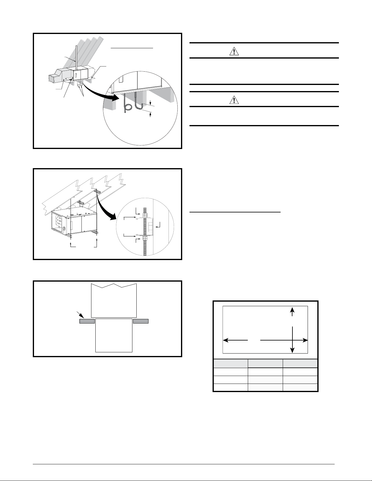
Figure 11. J951X*U Horizontal installation
Flue pipe vented
to outside
J-Trap
Height
3” Min.
Coil Plenum
Wood or
non-combustible
platform
Two-pipe installation shown
Combustion Air
Condensate
Drain Lines
Concrete
“A”
“B”
Opening in concrete floor
on a Platform
Nuts (x2)
Lag
Bolt
Threaded
Rod
Washer
and
Lockwasher
Nuts (x2)
Figure 12. J951X*U Horizontally Suspended
in an Attic
Floor
Furnace
Downflow Furnaces
WARNING:
The furnace must not be installed directly on
carpeting, tile, or any combustible material other
than wood flooring.
WARNING:
Failure to install the downflow sub-base kit may
result in fire, property damage or personal injury.
To install an J951X*D series gas furnace on combustible
flooring, a special sub-base is required. Downflow sub-base
kits are factory supplied accessories and are listed according
to the cabinet letter of the furnace. Refer to the technical sales
literature for part numbers. Please follow the instructions
provided with the kit.
A downflow sub-base kit is not necessary if the furnace is
installed on a factory or site-built cased air conditioning coil.
However, the plenum attached to the coil casing must be
installed so that its surfaces are at least 1” from combustible
construction.
Installation on a Concrete Slab
1. Create an opening in the floor according to the dimensions
in
Table 3.
2. Position the plenum and the furnace as shown in
Figure 13.
Inducer & Venting Options
To increase installation flexibility, the inducer assembly can be
rotated up to 3 different positions. Each variation has slightly
different requirements with regard to condensate disposal
and, in some cases, the need to seal the furnace cabinet.
IMPORTANT NOTE:
The Inducer Assembly must never be positioned to vent
downwards on horizontal installs.
Figure 13. Furnace on a Concrete Slab
If suspending the furnace from the ceiling, assemble a
support frame (
threaded rod. Fasten the frame together with nuts, washers,
and lockwashers. Secure the support frame to the rafters with
lag bolts. The furnace can also be suspended using steel
straps around each end of the furnace. The straps should
be attached to the furnace with sheet metal screws and to
the rafters with bolts.
It is recommended for further reduction of fire hazard that
cement board or sheet metal be placed between the furnace
and the combustible floor and extend 12 inches beyond the
front of the door and top of the furnace.
Sheet
Metal
Plenum
Figure 12) using slotted iron channel and full
MODEL #
J951X054BD
J951X072CD
J951X090CD
NOTE: Dimensions shown in Inches.
DIM. “A” DIM. “B”
16 5/8 19 1/4
20 1/8 19 1/4
20 1/8 19 1/4
Table 3. Cutout Dimensions
15
Page 16
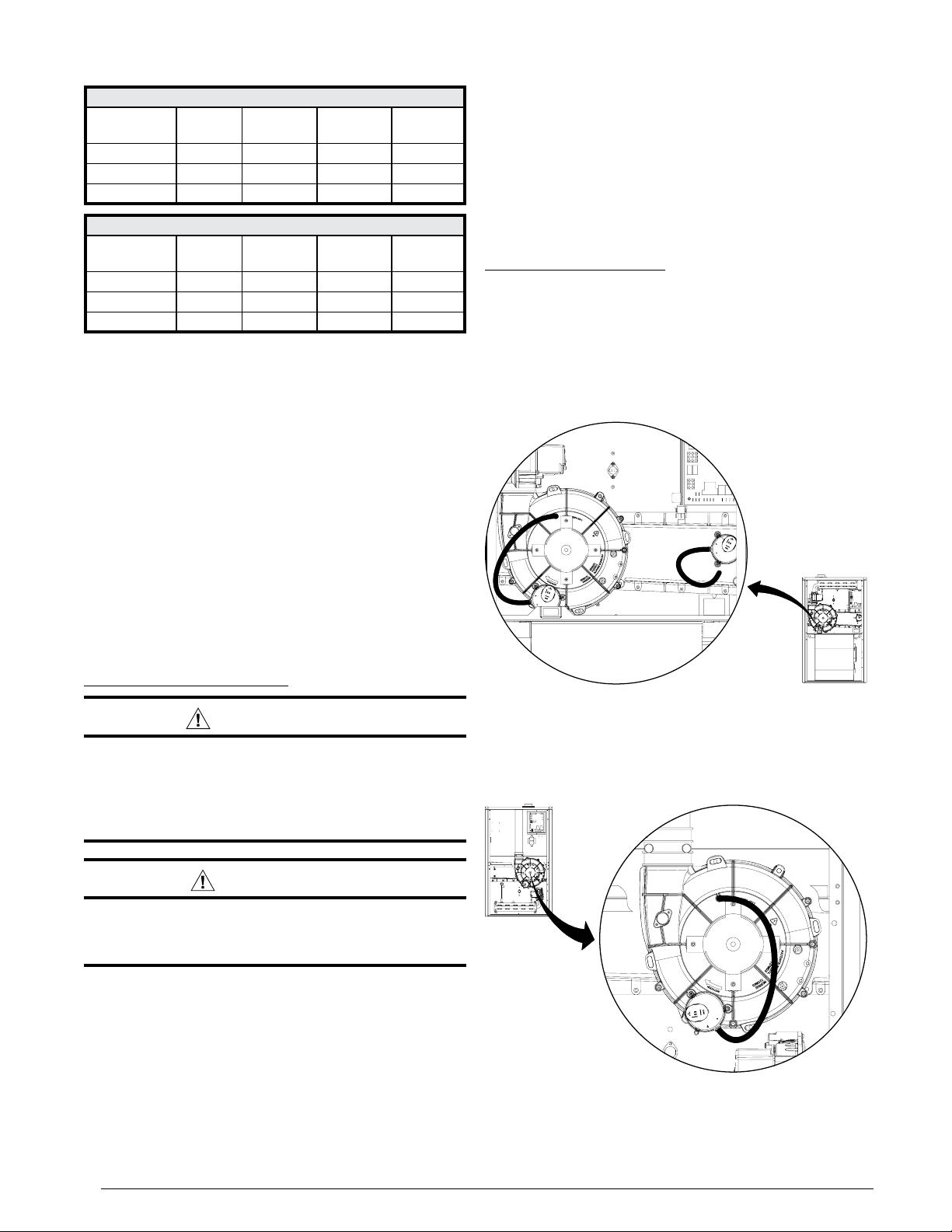
J951X*U & J951X*D SERIES - CONVENTIONAL (1 PIPE)
VENT
DIRECTION
Right Option 1 N/A N/A Option 9
Up N/A Option 5 Option 6 Option 10
Left Option 2 N/A N/A Option 11
J951X*U & J951X*D SERIES - DIRECT VENT (2-PIPE)
VENT
DIRECTION
Right Option 3 N/A N/A Option 12
Up N/A Option 7 Option 8 Option 13
Left Option 4 N/A N/A Option 14
UPFLOW
UPFLOW
HORIZONTAL
RIGHT
HORIZONTAL
RIGHT
HORIZONTAL
LEFT
HORIZONTAL
LEFT
DOWNFLOW
DOWNFLOW
Table 4. Vent & Inducer Blower Options
Before using Table 4, the number of pipes (1-pipe or 2-pipe)
connected to the furnace must be known. Find the proper
furnace style (upflow, horizontal, or downflow) and then the
side that the pipes will exit from the furnace. Finally select
the option that properly matches your installation type. For
J951X*U series, see
. For J951X*D series, see Figure 36 (page 39).
38)
Figure 34 (page 37) & Figure 35 (page
NOTE: It is important that Direct Vent (2-pipe) systems
maintain an airtight flow path from the air inlet to the flue
gas outlet. The furnace ships from the factory with two holes
in the cabinet for the air inlet and flue gas outlet. In certain
configurations, it is necessary to remove and relocate a plastic
plug in the furnace cabinet. If changing the position of the air
inlet and flue gas outlet, it is required that the previous hole
be closed off with the plastic plug to maintain air tightness
in the furnace. The hole locations for all furnace series are
shown in
Figure 29 and Figure 30.
Inducer Assembly Rotation
6. Remove the cabinet plug from side of furnace and reinstall
in hole on opposite side of cabinet.
7. Install in-line drain assembly and tubing.
8. Install all condensate drain lines. For J951X*U series,
see
Figure 34 (page 37) & Figure 35 (page 38). For
J951X*D series, see
Figure 36 (page 39).
9. Reconnect the electrical harness to the inducer assembly.
10. Reconnect the inducer assembly ground wire to the blower
deck or door.
11. Verify operation as detailed on the furnace label.
Pressure Switch Tubing
All upflow / horizontal furnaces have two switches, one
connected to the static tap on the inducer assembly and the
other to the collector box.
of pressure switch tubing for J951X*U furnaces. Downflow
(J951X*D) furnaces require only one switch connected to
the inducer’s static tap as shown in
Figure 14 displays the proper routing
Figure 15.
WARNING:
Inducer rotation must be completed before
the furnace is connected to gas and electric. If
both utilities have been connected, follow the
shutdown procedures printed on the furnace
label and disconnect the electrical supply.
CAUTION:
It is good practice to label all wires prior to
disconnection. Wiring errors can cause improper
and dangerous operation.
1. Disconnect the electrical harness from the inducer
assembly.
2. Remove the inducer assembly ground wire from the blower
deck.
3. Remove 3 screws securing the inducer assembly to the
header box.
4. Rotate the inducer assembly to its new position.
5. Secure the inducer assembly to the header box by
reinstalling the three screws. If the inducer assembly is
rotated to the left or right side of the furnace, use the extra
screw provided in the parts package.
Figure 14. Pressure Switch Tubing for
Upflow Furnaces
Models J951X038U, J951X054U, J951X072U,
J951X090U, J951X108U, & J951X120U
Figure 15. Pressure Switch Tubing for
Downflow Furnaces
Models J951X054D, J951X072D, & J951X090D
16
Page 17
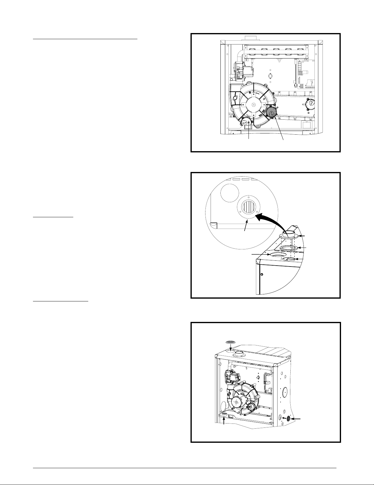
Alternate Pressure Switch Location
LOCATION
LOCATION
or Inlet
Grommet
ø 2 1/4” Rubber Grommet
In some inducer orientations, the inducer pressure switch may
interfere with gas pipe installation. Determine the side of the
cabinet the gas pipe will enter and see if the inducer pressure
switch needs to be moved. If the pressure switch interferes
with the gas pipe, use these instructions for relocating it to
an alternate location:
1. Shut off any electrical power to the furnace.
2. Label and disconnect the tubing and wires from the pressure
switch (
3. Remove two screws securing the pressure switch to the
inducer housing.
4. Remove the pressure switch from the mounts on the
inducer housing and relocate it to the other set of mounts
90° from previous location.
5. Secure the pressure switch with two screws.
6. Reconnect the tubes and wires to the pressure switch.
Figure 16).
PRIMARY
ALTERNATE
Accessories
The components below are included in the extra parts bag
that is supplied with the purchase of your furnace. Depending
on your particular installation, some of these components are
optional and may not be used. Please refer to the descriptions
and accompanying figures when installing these items.
NOTE: Some parts may not be supplied with each furnace.
Refer to the literature in the extra parts bag for the parts
included with the particular furnace.
Finish Flange
The finish flange must be installed to vent the combustion
air pipe through the top of the furnace. NOTE: For proper
installation it is important that the pipe and screw holes in the
finish flanges, gasket, and cabinet are aligned. See
1. Position flange gasket over hole in the furnace cabinet.
2. Position finish flange on top of the flange gasket.
NOTE: Make sure the flange is properly oriented so that
the FRONT lettering is located near the front of the furnace
as shown in
3. Secure flange and gasket to cabinet with three field supplied
sheet metal screws.
Rubber Grommets
The 2 1/4” rubber grommet is used to seal the opening
between the furnace cabinet and the 2” PVC vent pipe. The
rubber grommet should be installed in the 3” hole prior to
running the vent pipe out of cabinet. No sealants are required.
See
Figure 18.
The 7/8” rubber grommet is used to seal the opening between
the furnace cabinet and the gas pipe. The rubber grommet
should be installed in the 1 5/8” hole prior to running the gas
pipe into the cabinet. No sealants are required.
The 3/4” rubber grommet is used if venting out the left side of
the cabinet and the drain tube is routed through the blower
deck. Remove the plastic plug from the hole and install the
grommet before routing the drain tube.
Figure 17.
Figure 17.
Figure 16. Alternate Pressure Switch Location
FRONT
FRONT lettering must be
located near front
of furnace
Hole for
Flue
Vent Pipe
Finish
Flange
Flange
Gasket
Hole f
Air Vent Pipe
Figure 17. Finish Flange
(see note)
Ø 3/4” Rubber
Figure 18. Rubber Grommets
ø 7/8” Rubber
Grommet
17
Page 18
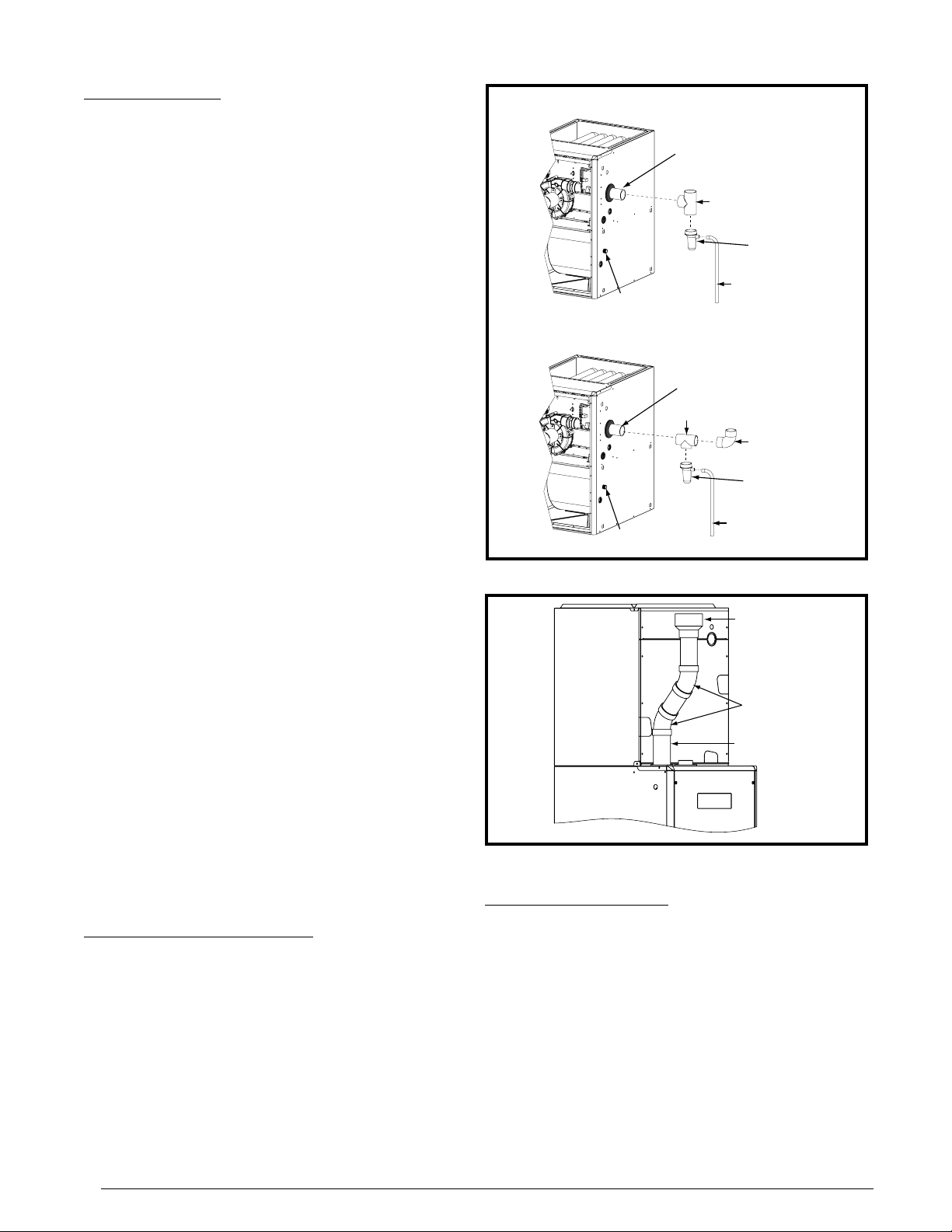
PVC Components
INSTALLATION OF PVC COMPONENTS
ubing (Field Supplied)
(Do Not Trap)
IMPORTANT NOTES:
• Before permanently installing these components, it is
recommended you dry-fit them first to ensure proper
fit and alignment with other vent pipes.
• The 2” PVC components shown in
Figure 19 are not
provided in the extra parts bag for *SC & *SL models.
However the PVC Trap (P/N 664659) can be purchased
thru your local distributor.
The 2” PVC tee, reducer, PVC Trap and 1/2” X 1/2” hose
barb are used when the inducer is rotated to vent out thru
the left or right side of the furnace cabinet. See
Figure 19.
The 1/2” X 3/4” hose barb can be used to route the condensate
drain to the outside of the cabinet. It must be installed from
inside the cabinet with the threaded end inserted thru the 1
1/16” hole. The condensate drain should be connected to
the barbed end. Attach 1” PVC drain line to the threaded
end. See
Figure 29 (page 29) or Figure 30 (page 29) for
hole location.
Typical Orientation
1. Install the PVC Tee vertically on the 2” vent pipe that is
extending out the side of the cabinet. Permanently bond
them together using appropriate primer and cement. Refer
to the typical orientation shown in
2. Install the reducer or PVC trap (if supplied) on the bottom
end of the PVC Tee. Permanently bond them together
using appropriate primer and cement.
3. Install the 1/2” x 1/2” hose barb on the 2” PVC reducer.
NOTE: Do not over tighten! Use an adequate amount of
Teflon tape on the threads. Do not use liquid sealants.
4. Verify all connections and joints for tight fit and proper
alignment with other vent pipes.
Figure 19.
(TYPICAL ORIENTATION)
2” PVC Pipe from Inline
Drain Assembly
(Not Included)
2” PVC Tee
PVC TRAP
Not Included in
*SC & *SL Models
1/2” T
1/2” x 3/4”
Hose Barb
INSTALLATION OF PVC COMPONENTS
(ALTERNATE ORIENTATION)
2” PVC Pipe from Inline
Drain Assembly
(Not Included)
2” PVC Tee
1/2” x 3/4”
Hose Barb
Drain Line Attached
to PVC Trap
(Do Not Trap)
2” PVC Elbow
(Field Supplied)
PVC TRAP
Not Included in
*SC & *SL Models
1/2” Tubing (Field Supplied)
Drain Line Attached
to PVC Trap
Figure 19. PVC Components
2” x 3” PVC
Coupling
Alternate Orientation
1. Install the 2” PVC Tee horizontally on the 2” vent pipe that
is extending out the side of the cabinet. Permanently bond
them together using appropriate primer and cement. Refer
to the alternate orientation shown in
2. Install the 2” PVC Elbow on the end of the 2” PVC Tee.
Permanently bond them together using appropriate primer
and cement.
3. Install the reducer or PVC trap (if supplied) on the bottom
end of the PVC Tee. Permanenly bond them together using
appropriate primer and cement.
4. Install the 1/2” x 1/2” hose barb on the 2” PVC reducer.
NOTE: Do not over tighten! Use an adequate amount of
Teflon tape on the threads. Do not use liquid sealants.
5. Verify all connections and joints for tight fit and proper
alignment with other vent pipes.
Optional PVC Pipe Installation
When running the 2” PVC pipe out through the top of the
J951X*U upflow furnace, there may be possible clearance
issues when transitioning the PVC pipe from 2” to 3”:
• If the size of the PVC flue needs to be increased from 2”
to 3”, two, 2” x 45° PVC elbows may be used to achieve
the clearances needed between the coil box and the 2” x
3” coupling. See
• Install the 2” x 3” coupling in the vertical run only. If the
coupling is installed horizontally, it will allow water to build
up inside the furnace and cause a lock out condition.
• To avoid the clearance issue, it is recommended that the
furnace be vented through the left side or the right side of
the cabinet.
Figure 20.
Figure 19.
Coil Box
2” x 450 PVC
Elbow
2” PVC Pipe
Figure 20. Optional PVC Pipe Installation
Condensate Drain Lines
If the furnace is installed in an area where temperatures
fall below freezing, special precautions must be made
for insulating condensate drain lines that drain to the
outdoors. If condensate freezes in the lines, this will
cause improper operation or damage to the furnace. It
is recommended that all drain lines on the outside of
the residence be wrapped with an industry approved
insulation or material allowed by local code.
• The method for disposing condensate varies according to
local codes. Consult your local code or authority having
jurisdiction.
• The condensate drain line must be trapped using a kit
(P/N- 922485) or field supplied parts. After the drain trap,
condensate can continue to the drain by connecting to a
recommended 3/4” ID minimum drain line, but no smaller
18
Page 19
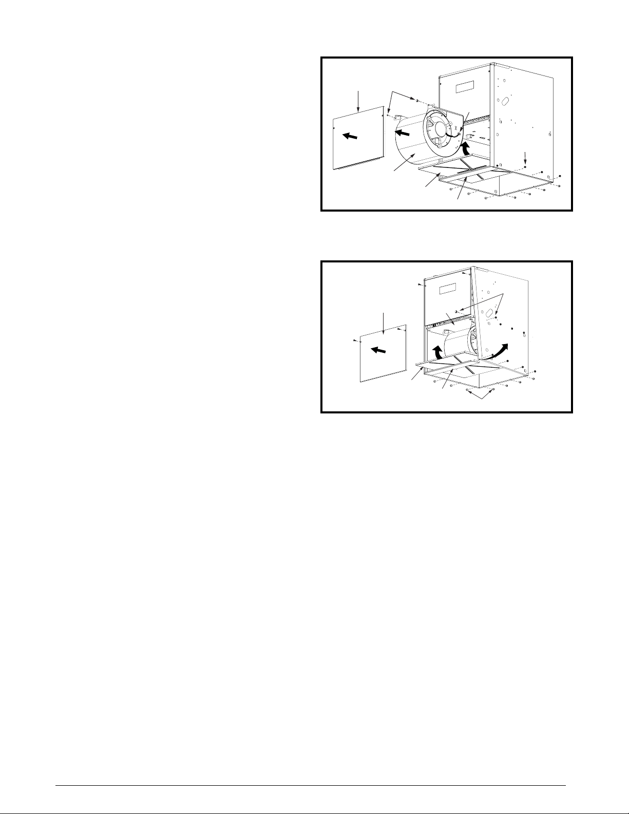
than the original tubing ID supplied by the manufacturer.
Screws
The drain line should slope downward away from the
furnace to ensure proper drainage.
• The placement of the condensate drain lines will depend
on the configuration selected in
Table 4 (page 16). The
drain lines can be routed out the left or right side of the
furnace, but must maintain a downward slope to ensure
proper condensate drainage. The J-trap may need to be
rotated to the side that matches your setup.
For J951X*U series, see
35 (page 38)
. To rotate the J-trap, loosen the clamp on the drain
39)
. For J951X*D series, see Figure 36 (page
Figure 34 (page 37) & Figure
tube, rotate the J-trap to either side, and retighten the
clamp.
• It is permissible to locate the trap away from the
furnace. The condensate drain system (J-trap and drain
tube) should be no more than 30 equivalent feet while
maintaining 1/4” per foot slope, and insulated if located in
an unconditioned space.
THREE GENERAL PRINCIPLES APPLY:
• Each condensate drain must be trapped separately using
a J-Trap or field supplied loop. After individually trapping
the condensate lines, it is acceptable to combine the
drains.
• There must always be a drain attached to the collector at
the outlet of the secondary heat exchanger.
• There must always be a drain at the lowest point of the
venting system. NOTE: If using a condensate pump, the
furnace drain line must be installed above the pumps
water line.
EXCEPTIONS & CLARIFICATIONS TO THE
GENERAL RULES:
• If the vent exits the furnace horizontally, the vent may be
turned vertically with a tee. The drip leg formed by the
tee must include a drain. (Option 1, Option 3, Option 4,
Option 11, Option 12, & Option 14)
• In certain cases, it is permitted to drain the inducer back
into the top drain of the collector. This drain must not
sag in the middle. (Option 1, Option 3, Option 5, Option
7, Option 9, Option 10, Option 12, & Option 13)
Bottom Panel Removal
The steps listed below describe how to remove the bottom
panel from the furnace. See
1. Remove the door from the blower compartment.
2. Disconnect the wires from the blower motor plug.
3. Remove two screws securing the blower assembly to the
furnace.
4. Carefully pull the blower assembly out thru the front of the
furnace.
5. Remove all screws securing bottom panel to bottom of
furnace and front brace.
6. Lift up and slide bottom panel out through front of furnace.
7. Reinstall the blower assembly in reverse order.
Figure 21.
Door
Screws
Blower
Plug
Screws
Blower
Assembly
Bottom
Panel
Figure 21. Bottom Panel Removal
Screws
Door
Bottom
Panel
Blower
Deck
Front
Brace
Figure 22. Alternate Removal Method
Alternate Bottom Panel Removal
If the bottom panel cannot be removed using the previous
instructions, the steps below are an alternate method for
removing the bottom panel. See
1. Remove the door from the blower compartment .
2. Remove all screws securing the bottom panel to the front
brace.
3. Remove two screws securing the furnace cabinet to the
blower deck.
4. Remove all screws securing the furnace cabinet to the
bottom panel.
5. Remove the screw securing the bottom corner of the
furnace cabinet to the front brace.
6. Carefully spread the bottom corner of the furnace cabinet
outwards while sliding the bottom panel out through the
front of the furnace.
7. Reassemble the furnace in reverse order.
Figure 22.
19
Page 20
GAS SUPPLY & PIPING
WARNING:
FIRE OR EXPLOSION HAZARD
• Failure to follow safety warnings exactly could
result in serious injury, death or property
damage.
• Installation and service must be performed
by a qualified installer, service agency or the
gas supplier.
• Do not store or use gasoline or other
flammable vapors and liquids in the vicinity
of this or any other appliance.
WHAT TO DO IF YOU SMELL GAS
• Do not try to light any appliance.
• Do not touch any electrical switch; do not
use any phone in your building.
• Leave the building immediately.
• Immediately call your gas supplier from a
neighbor’s phone. Follow the gas supplier’s
instructions.
• If you cannot reach your gas supplier, call
the fire department.
• All gas piping must be installed in compliance with
local codes and utility regulations. In the absence of
local codes the gas line installation must comply with
the latest edition of the National Fuel Gas Code (ANSI
Z223.1) or (CAN/CSA B149.1) Installation Codes.
• Some local regulations require the installation of a
manual main shut-off valve and ground joint union
external to the furnace as shown in
&
Figure 24 (page 21). The shut-off valve should be
readily accessible for service and/or emergency use.
Consult the local utility or gas supplier for additional
requirements regarding placement of the manual main
gas shut-off.
• Per ANSI 21.47, A 1/8-inch NPT plugged tapping,
accessible for test gauge connection, must be installed
immediately upstream of the gas supply connection to
the furnace external to the cabinet. If local codes allow
the use of a flexible gas appliance connector, always
use a new listed connector. Do not use a connector
that has previously serviced another gas appliance.
• Gas piping must never run in or through air ducts,
chimneys, gas vents, or elevator shafts.
• Compounds used on threaded joints of gas piping
must be resistant to the actions of LP propane gas.
• The main gas valve and main power disconnect to the
furnace must be properly labeled by the installer in
case emergency shutdown is required.
• Flexible gas connectors are not recommended for this
type of furnace but may be used if allowed by local
jurisdiction. Only new flexible connectors may be
used. Do not use a connector which has previously
serviced another gas appliance.
• A drip leg should be installed in the vertical pipe run
to the unit. See
Figure 23 or Figure 24.
Figure 23 (page 21)
Table 6 (page 32) lists gas flow capacities for standard pipe
sizes as a function of length in typical applications based on
nominal pressure drop in the line.
The furnace may be installed with either left or right side gas
entry. When connecting the gas supply, provide clearance
between the gas supply line and the entry hole in the furnace
casing to avoid unwanted noise and/or damage to the furnace.
Typical gas hookups are shown in
Figure 23 & Figure 24.
Leak Check
WARNING:
FIRE OR EXPLOSION HAZARD
Failure to follow safety warnings exactly could
result in serious injury, death or property
damage.
Never test for gas leaks with an open flame.
Use a commercially available soap solution
made specifically for the detection of leaks
to check all connections. A fire or explosion
may result causing property damage, personal
injury or loss of life.
After the gas piping to the furnace is complete, all connections
must be tested for gas leaks. This includes pipe connections
at the main gas valve, emergency shutoff valve and flexible
gas connectors (if applicable). The soap and water solution
can be applied on each joint or union using a small paintbrush.
If any bubbling is observed, the connection is not sealed
adequately and must be retightened. Repeat the tightening
and soap check process until bubbling ceases.
IMPORTANT NOTE:
When pressure testing gas supply lines at pressures
greater than 1/2 psig (14 inch W.C.), the gas supply
piping system must be disconnected from the furnace
to prevent damage to the gas control valve. If the test
pressure is less than or equal to 1/2 psig (14 inch W.C.),
close the manual shut-off valve.
High Altitude Application (Natural Gas Only)
High altitude conversion with this furnace depends on
the installation altitude and the heating value of the gas.
Installation of this furnace at altitudes above 2,000 feet
shall be in accordance with local codes, or in the absence
of local codes, the National Fuel Gas Code, ANSI Z223.1/
NFPA 54 or National Standard of Canada, Natural Gas &
Propane Installation Code CSA B149.1. Please consult your
local code authority.
WARNING:
The reduction of input rating necessary for high
altitude installation may only be accomplished
with factory supplied orifices. Do not attempt to
drill out orifices in the field. Improperly drilled
orifices may cause fire, explosion, carbon
monoxide poisoning, personal injury or death.
20
Page 21
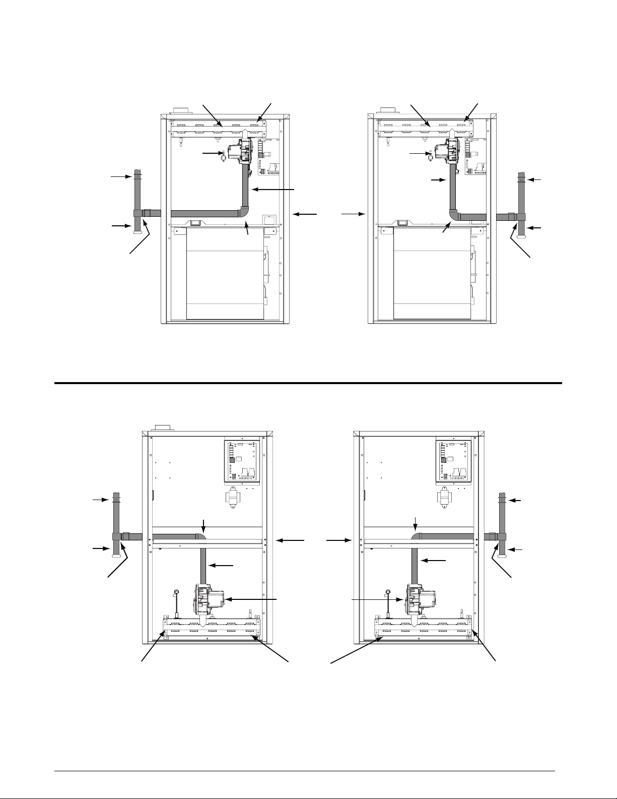
J951X*U SERIES
Manifold
Drip Leg
Dr
Shut-Off
Shut-Off
Valve
Ground
Joint
Union
J951X*D SERIES
NOTE B: Inducer assembly omitted for clarity of pipe installatio
Dr
g
Shut-Off
Burner
Assembly
Manifold
Burner
Assembly
Valve
ip Leg
Note “A”
Ground
Joint
Union
See
Gas
Valve
See
Note “B”
Elbow
Left Side Entry
Pipe
Nipple
Plug
Gas
Valve
Pipe
Nipple
See
Note “B”
Right Side Entry
Figure 23. Typical Gas Connections - Upflow Models
See
Note “A”
Elbow
Valve
ip Leg
Ground
Ground
Joint
Joint
Union
Union
See
Note “A”
Manifold
Elbow
Plug
See
Note “B”
Left Side Entry
NOTE A: Consult local codes for Shut-Off Valve location requirements
Pipe
Nipple
Gas
Valve
Burner
Assembly
Note “B”
Gas
Valve
Figure 24. Typical Gas Connections - Downflow Models
Elbow
See
Right Side Entry
Pipe
Nipple
See
Note “A”
Shut-Off
Valve
Drip Le
Ground
Joint
Union
Manifold
21
Page 22
The furnaces are shipped from the factory with orifices and
gas regulator settings for natural gas operation at sea level
altitudes. At 2,000 feet, the NFGC requires that this appliance
be derated 4% for each 1,000 feet of altitude.
For example, the input needs to be reduced 8% at 2,000
feet, 12% at 3,000 feet, etc. This deration is in reference to
the input rate and gas heating value at sea level.
To derate the furnace requires knowing the heating value of
the gas at the installation site. Heating values at particular
job sites vary for two reasons:
1. The chemical mixture of the gas varies across regions
and is expressed as the “sea level heating value”.
2. The heating value varies by altitude. For this reason,
especially in high altitude areas, the local gas utility
specifies the heating value at the residence’s gas meter
as the “local value”.
For added flexibility, two tables have been provided for natural
gas installations with high or low heating values at sea level.
Table 10 & Table 11 (page 34) contain the manifold pressure
and orifice sizes to use at various altitudes.
for natural gas installations with a heating value of more than
1,000 Btu per cubic foot and
1,000 Btu per cubic foot. To determine which table to use:
1. Consult the local utility for the local heating value at your
installation site.
2. From
3. If your sea level heating value is HIGH, use
After changing the regulator pressure or the orifices, it is
required that you measure the gas input rate. This may be
accomplished in the usual way, by clocking the gas meter
and using the local gas heating value. See Verifying and
Adjusting the Input Rate section on
Table 9 (page 33), find your local heating value as
supplied by the utility company. Follow down the column
and stop at your altitude level.
it’s LOW, use
Elevation: ......................................................5,000 feet
Type of Gas: .............................................. Natural Gas
Local Heating Value of Gas: .................................. 750
From
Table 9, find 750 and follow down the column, stop
at the 5,000 feet row. The heating value listed is LOW.
Table 11 will be used to determine orifice size and manifold
pressure.
Table 11. See Example below.
Table 11 (LOW) is for less than
EXAMPLE
Table 10 (HIGH) is
Table 10 or if
page 25.
IMPORTANT NOTE:
Observe the action of the burners to make sure there is
no yellowing, lifting or flashback of the flame.
For US installations only: To avoid nuisance tripping
at altitudes from 7500 to 10,000 feet, a pressure switch
conversion may be required. Consult the tables in the LP
and High altitude and LP gas conversion kit for installations
in the US.
Converting from Natural Gas to LP / Propane
WARNING:
The furnace was shipped from the factory
equipped to operate on natural gas. Conversion
to LP / Propane gas must be performed by
qualified service personnel using a factory
supplied conversion kit. Failure to use the proper
conversion kit can cause fire, explosion, property
damage, carbon monoxide poisoning, personal
injury, or death.
Conversion to LP / Propane is detailed in the installation
instructions provided with the conversion kit. Generally, this
will require the replacement of the burner orifices and the
spring found under the cap screw on the pressure regulator.
Approved conversion kits are listed below:
• Installations in the United States: For Propane (LP)
conversion or for LP gas installations in altitudes between
2,000 ft. and 10,000 ft. above sea level, use the LP &
High Altitude LP Gas Conversion Kit (P/N 905028) for
Installations in the United States. Please follow the
instructions provided with the kit.
• Installations in Canada: For Propane (LP) conversion or
for LP Gas installations in altitudes between zero and
4,500 ft. above sea level, use the LP & High Altitude
LP Gas Conversion Kit (P/N 905029) for Installations in
Canada. Please follow the instructions provided with
the kit.
If the installation is in the U.S. and above 2,000 ft., refer to
Table 8 (page 33) to determine the correct orifice size and
regulator pressure. See
EXAMPLE
Elevation: ......................................................5,000 feet
Type of Gas: ............................................ Propane Gas
Input BTUH of Furnace: ....................................72,000
From
Table 8, find 5,000 and follow across the row, stop
at the 72,000 btu column. The manifold pressure listed
is 10.0 and the orifice size is 57.
When conversion is complete, verify the manifold pressure
and input rate are correct as listed in the table.
Example below.
22
Page 23
ELECTRICAL WIRING
WARNING:
ELECTRICAL SHOCK, FIRE OR
EXPLOSION HAZARD
Failure to follow safety warnings exactly could
result in serious injury, death or property
damage.
Improper servicing could result in dangerous
operation, serious injury, death or property
damage.
• Before servicing, disconnect all electrical
power to furnace.
• When servicing controls, label all wires prior
to disconnecting. Reconnect wires correctly.
• Verify proper operation after servicing.
• Electrical connections must be in compliance with all
applicable local codes with the current revision of the
National Electric Code (ANSI/NFPA 70).
• For Canadian installations the electrical connections
and grounding shall comply with the current Canadian
Electrical Code (CSA C22.1 and/or local codes).
IMPORTANT NOTE:
If replacing any of the original wires supplied with the
furnace, the replacement wire must be copper wiring and
have a temperature rating of at least 105° F (40° C). For
electrical specifications, refer to the furnace nameplate
or
Table 5 (page 23).
Line Voltage Wiring
It is recommended that the line voltage (115 VAC) to the
furnace be supplied from a dedicated branch circuit containing
the correct fuse or circuit breaker for the furnace as listed
in
Table 5 (page 23).
The installer should become familiar with the units wiring
diagram before making any electrical connections to the
unit. See
Figure 31 (page 30), Figure 32 (page 31), or
the unit wiring label.
IMPORTANT NOTES:
An electrical disconnect must be installed readily
accessible from and located within sight of the furnace.
See
Figure 25 (page 24) or the wiring diagram label inside
of the control door. Any other wiring methods must be
acceptable to authority having jurisdiction.
Proper line voltage polarity must be maintained in order
for the control system to operate correctly. Verify the
incoming neutral line is connected to the white wire and
the incoming HOT line is connected to the black wire.
The furnace will not operate unless the polarity and
ground are properly connected as shown in
Figure 25.
Grounding
WARNING:
To minimize personal injury, the furnace cabinet
must have an uninterrupted or unbroken electrical
ground. The controls used in this furnace require
an earth ground to operate properly. Acceptable
methods include electrical wire or conduit
approved for ground service. Do not use gas
piping as an electrical ground!
FURNACE
MODEL
NUMBER
J951X038BU
J951X054BU
J951X072CU
J951X090CU
J951X108DU
J951X120DU
J951X054BD
J951X072CD
J951X090CD
THERMOSTAT WIRE GAUGE
FURNACE
INPUT
(BTUH)
38,000 17 ½ 115-60-1 127 103 9.3
54,000 17 ½ 115-60-1 127 103 9.3
72,000 21 115-60-1 127 103 9.3
85,000 21 115-60-1 127 103 12.0
108,000 24 ½ 115-60-1 127 103 12.0
115,000 24 ½ 115-60-1 127 103 12.0
54,000 17 ½ 115-60-1 127 103 9.3
72,000 21 115-60-1 127 103 9.3
90,000 21 115-60-1 127 103 12.0
24 55 ft. 25 ft.
22 90 ft. 45 ft.
20 140 ft. 70 ft.
18 225 ft. 110 ft.
CABINET
WIDTH
(IN.)
NOMINAL
ELECTRICAL
SUPPLY
MAXIMUM
OPERATING
VOLTAGE
RECOMMENDED THERMOSTAT WIRE LENGTH
2 - WIRE
(HEATING)
MINIMUM
OPERATING
VOLTAGE
MAXIMUM
FURNACE
AMPERES
4 OR 5 WIRE
(COOLING)
Table 5. Wire Length & Voltage Specifications
23
Page 24
Field Supplied
Field Supplied
Field Line Voltage Wiring
e.
NOTE: Connections made within the furnace burner compartment do not require a junction box.
A/C
For
ELECTRONIC AIR CLEANER
HUMIDIFIER TAP
Factory Line Voltage Wiring
Fused Service
Panel
Disconnect within
Sight of Furnace
Field Supplied
Panel Connector
Black (Hot)
White (Neutral)
Green or Bare (Ground)
Ground
Junction Box (may be int. or ext. to the furnace). These connections can be made in the field supplied disconnect at the furnac
Figure 25. Line Voltage Field Wiring
Thermostat / Low Voltage Connections
• The furnace is designed to be controlled by a 24 VAC
thermostat. The thermostat’s wiring must comply with the
current provisions of the NEC (ANSI/NFPA 70) and with
applicable local codes having jurisdiction.
• The thermostat must be installed according to the
instructions supplied by the thermostat manufacturer.
Low voltage connections (24 VAC) from the thermostat
are wired to the terminal strip on the integrated control
in the furnace.
Figure 26 contains the proper connections
for heating only (two-wire) and heating/cooling (four-wire)
applications. Recommended minimum wire gauge for
thermostat wiring is shown in
Table 5 (page 23).
• The thermostat should be mounted about 5 feet above
the floor on an inside wall. DO NOT install the thermostat
on an outside wall or any other location where its
operation may be adversely affected by radiant heat from
fireplaces, sunlight, or lighting fixtures, and convective
heat from warm air registers or electrical appliances.
Refer to the thermostat manufacturer’s instruction sheet
for detailed mounting information.
Twinning
WARNING:
When servicing either twinned furnace, power
must be turned off on both furnaces. Failure to
comply may result in improper operation leading
to damage to the furnaces or personal injury!
Single stage furnaces are not supplied with a built-in twinning
capability. Other valuable features and enhancements were
made to the new control that made it necessary to remove
the twinning capability. For twinning of single stage furnaces
with PSC motors, a twinning kit is available for purchase.
Refer to the technical sales literature for part numbers. Please
follow the instructions provided with the kit.
Single stage furnaces are equipped with a fixed speed blower;
therefore, the twin terminal on the blower control boards
(
Figure 27 (page 25)) may be used to twin the single stage
furnaces. The twinning system requires a relay (P/N 624843)
in the secondary furnace for proper twinning.
For proper twinning of fixed speed furnaces the following
criteria must be met:
• Both furnaces and motors must be the same size.
• Both motors must be on the same speed for cooling and
heating.
COOL
HEAT
XFMR
SPEED
SELECT
FLAME
BLOWER
DELAY
EAC
L1
Black
White
Ground
STATUS
OFF
HIGH
MH
JUMPER PIN
SETUP
H
MH
ML
L
RED
GREEN
YELLOW
180
120
90
60
LOW
ML
120
60
MOTOR
SPEED
TAPS
180
90
Black
White
Connect
R & W
Heating
Only
NOTE: The “Y” terminal
on the control board must
be connected to the
thermostat for proper
cooling mode operation.
FIELD WIRING
LOW VOLTAGE
CONNECTION
Ground
CONDENSING
ROOM
THERMOSTAT
R
C
Y
G
W
NEUTRAL LEADS
UNIT
Black
White
3 AMP
FUSE
6 3
5
4
RCYGW
63
9
2
5
8
1
4
7
2
1
NEUTRALS
CONDENSING UNIT
CONTROL BOX
COM
FAN
24V
HUM
Figure 26. Low Voltage Field, Four-wire
Heating/Cooling Applications
• Both furnaces must have a common return duct and
common supply plenum.
• Both furnaces must be the same phase and on the same
leg of power.
• Furnaces equipped with variable speed iSEER™
motors may not be twinned under any circumstances.
For twinning of single stage furnaces equipped with
fixed speed blowers, refer to Figure 27 and the following
instructions:
1. Turn off all power to both furnaces.
2. Attach a wire between the two twin terminals on the blower
control boards. Use field supplied wire and 3/16” wire
terminals.
NOTE: One furnace can be used for one stage of heating
and the other furnace can be used for the second stage of
heating. The installer also has the choice of running one
furnace only or both furnaces. In both cases the blowers will
run at the same time and at the same speeds:
One stage heating
• Connect the thermostat wires to the primary furnace
control board. Mount the relay on the bracket on the
secondary furnace.
• Connect W from the primary furnace to the coil side of the
relay (using field supplied wire and 3/16” terminals).
24
Page 25
AC
CE
PRIMARY FURNACE
SECONDARY FURNACE
SINGLE STAGE HEATING (WITH TWINNING)
UNIT
6-Pin Wiring
Harness
AC
UNIT
6-Pin Wiring
Harness
THERMOSTAT
TWIN TERMINAL
PRIMARY FURNACE
TWO STAGE HEATING (WITH TWINNING)
THERMOSTAT
TWIN TERMINAL
GYR
R
GYC
FURNACE
Port
BOARD
Expansion
BLOWER
CONTROL
BOARD
Port
Expansion
GYR
R
GYC
FURNACE
BOARD
Port
Expansion
BLOWER
CONTROL
BOARD
Port
Expansion
W2
W1
C
W
6-Pin Wiring
Harness
SECONDARY FURNA
W2
W1
C
W
6-Pin Wiring
Harness
RELAY
NO
COM
WHITE
RED
R
C
Y
FURNACE
Port
BOARD
Expansion
BLOWER
CONTROL
BOARD
Port
Expansion
TWIN TERMINAL
RELAY
NO
COM
WHITE
RED
FURNACE
BOARD
Port
Expansion
BLOWER
CONTROL
BOARD
Port
Expansion
TWIN TERMINAL
G
W
GYCR
W
Figure 27. Single & Two Stage Twinning
• Connect C from the primary furnace to the coil side of
the relay (using field supplied wire and 3/16” terminals).
NOTE: Make sure connections are made on opposite
sides of the coil.
• Connect R from the secondary furnace control board to
the COM side of the relay (use included red wire).
• Connect W from the secondary furnace control board to
NO side of the relay (use included white wire).
Two stage heating
• Connect the thermostat wires to the furnace control
board (except W2). Mount the relay on the bracket on the
secondary furnace.
• Connect W1 from the thermostat control to W of the
primary furnace.
• Connect W2 from the thermostat to the coil side of the
relay (using field supplied wire and 3/16” terminals)
• Connect C from the primary furnace to the coil side of the
relay (using field supplied wire and 3/16” terminals).
NOTE: Make sure connections are made on opposite
sides of the coil
• Connect R from the secondary furnace control board to
the COM side of the relay (use included red wire).
• Connect W from the secondary furnace control board to
NO side of the relay (use included white wire).
Heat Anticipator
Set the heat anticipator according to the instructions supplied
by the thermostat manufacturer. To determine the heat
anticipator setting:
1. Add the current draw of the system components; or
2. Measure the current flow on the thermostat R-W circuit
after the circulating blower motor has started.
START-UP & ADJUSTMENTS
Pre-Start Check List
√ Verify the polarity of the connections are correct, the line
voltage power leads are securely connected and the
furnace is properly grounded.
√ Verify the thermostat wires (R, W, Y, & G) are securely
connected to the correct leads on the terminal strip of the
circuit board.
√ Verify the jumper setting (for fan speed) on the control
board. To select fan speed, see
jumper on the control board.
√ Verify the gas line service pressure does not exceed 10.0
inches of W.C., and is not less than 4.5 inches W.C. for
natural gas. For LP gas the line service pressure must
not exceed 14 in. W.C., and must not be less than 11.0
in. W.C.
√ Verify the roll-out and manual reset switch is closed. If
necessary, press the red button to reset a switch. DO
NOT install a jumper wire across a switch to defeat its
function. If a switch reopens on startup, DO NOT reset
the switch without identifying and correcting the fault
condition.
√ Verify the blower door is in place, closing the door switch
in the line voltage circuit.
√ Verify the gas line has been purged and all connections
are leak free.
Start-up Procedures
Do not perform these steps until all of the checks in the
previous steps have been completed:
1. Set the thermostat to the lowest setting.
2. Turn off all electrical power to the furnace.
3. Follow the Operating Instructions on the label attached to
the furnace.
4. Set the thermostat above room temperature and verify the
Operating Sequence (
page 27).
5. After 5 minutes of operation, set the thermostat below
room temperature and verify steps 9 - 10 of the Operating
Sequence.
Verifying & Adjusting Input Rate
The input rate must be verified for each installation to prevent
over-firing of the furnace. NOTE: The input rate must not
exceed the rate shown on the furnace rating plate. At altitudes
above 2,000 feet, it must not exceed that on the rating plate
less 4% for each 1,000 feet. To determine the exact input
rate, perform the following procedures:
1. Shut off all other gas fired appliances.
2. Start the furnace and run it for at least 3 minutes.
3. Measure the time (in seconds) required for the gas meter
to complete one revolution.
4. Convert the time per revolution to cubic feet of gas per
hour using
5. Multiply the gas flow rate in cubic ft per hr by the heating
value of the gas in Btu per cubic ft to obtain the input rate
in Btuh. See example.
• Time for 1 revolution of a gas meter with a 1 cubic ft
dial = 40 seconds.
• From
• Local heating value of the gas (obtained from gas
supplier) = 1,040 Btu per cubic ft.
• Input rate = 1,040 x 90 = 93,600 Btuh.
Table 6 (page 32).
EXAMPLE:
Table 6 read 90 cubic ft gas per hr.
Figure 26 and set the
25
Page 26

Capscrew
from the factory pre-wired for 4 blower speeds. There is a fifth
alternate speed available on the motor. To utilize the alternate
speed, remove the wire at the motor plug of the desired speed to
be changed (H, MH, ML, L). Reconnect this wire to the alternate
motor plug speed tap.
Verifying Burner Operation
CAUTION:
Figure 28. Regulator Capscrew
6. The manifold pressure must be set to the appropriate
value for each installation by a qualified installer, service
agency or the gas supplier.
WARNING:
Do not attempt to drill the gas orifices. Use only
factory supplied orifices. Improperly drilled
orifices may cause fire, explosion, carbon
monoxide poisoning, personal injury or death.
a.) Obtain the manifold pressure setting required for
this installation by referring to
Propane or
for Natural Gas.
34)
b.) Remove the regulator capscrew (
INLET side of the regulator.
c.) Slowly turn the adjustment screw inside the regulator
to obtain the appropriate manifold pressure.
NOTE: Turning the screw clockwise increases the
pressure and turning the screw counter-clockwise
decreases the pressure. To prevent backing the screw
all the way out from the valve, turn the screw slowly.
d.) Replace and tighten the regulator capscrew over the
adjustment screw.
Table 10 (page 34) or Table 11 (page
Verifying & Adjusting Temperature Rise
After installation of the furnace, confirm the temperature rise
of the furnace is within the limits specified on the rating plate.
Any temperature rise outside the specified limits could result
in premature failure of the heat exchanger.
1. Place thermometers in the return and supply air stream
as close to the furnace as possible. The thermometer on
the supply air side must be shielded from direct radiation
from the heat exchanger to avoid false readings.
2. Adjust all registers and duct dampers to the desired position
and run the furnace for 10 to 15 minutes before taking
any temperature readings. The temperature rise is the
difference between the supply and return air temperatures.
For typical duct systems, the temperature rise will fall within the
limits specified on the rating plate with the blower speed at the
factory recommended setting. If the measured temperature
rise is outside the specified limits, it may be necessary to
change the speed of the blower.
NOTE: Lowering the blower speed will increase the
temperature rise and a higher blower speed will decrease
the temperature rise.
The furnace is equipped with a 5-speed ECM motor. Heating
and cooling speed selection is made by moving the switch on the
integrated control inside of the furnace. The furnace is shipped
Table 8 (page 33) for
Figure 28) from the
The door over the burners may only be open
for inspection purposes only. The door must be
installed during unattended operation.
1. Remove the burner compartment door.
2. Set the thermostat above room temperature and observe
the ignition sequence. NOTE: The burner flame should
carry over immediately between all burners without lifting
off, curling, or floating. The flames should be blue, without
yellow tips.
3. After validating the flame, change thermostat setting to
below room temperature.
4. Verify the burner flame is completely extinguished.
5. Replace the burner compartment door.
Verifying Operation of the Supply Air Limit
Switch
NOTE: A properly functioning limit switch should turn off
the gas valve when the return is blocked (time depends on
how well the return air is blocked). The circulating air and
combustion blowers should continue to run when the limit
switch opens.
1. Verify the blower door is securely mounted in place and
that there is power to the furnace.
2. Block the return airflow to the furnace by installing a closeoff plate in place of or upstream of the filter(s).
3. Set the thermostat above room temperature and observe
the Operating Sequence.
4. Remove the close-off immediately after the limit switch
opens. If the furnace continues to operate with no return
air, set the thermostat below room temperature, shut off
power to the furnace, and replace the limit switch.
System Operation
(Gas) Heating Mode
When the thermostat calls for heating, the circuit between R
and W is completed. The furnace control board initiates the
ignition sequence. Approximately 30 seconds after the gas
flame has proven, the blower motor will start. The blower will
continue to operate after the call for heat has been removed
for a selectable (switch on furnace control board) number of
seconds. NOTE: All on- and off-delays for heating continue
to be controlled by the furnace control board.
Cooling Mode
When the thermostat calls for cooling or heat pump heating,
the circuit between R, G, and Y (O is ignored by the blower)
is completed. The blower runs at the selected cooling motor
torque.
Manual Fan
Select the speed using the jumper on the control board.
26
Page 27
Fault Conditions
There is a green and a red LED (labeled “Status”) on the
motor control board to provide system faults as described
below. Refer to
control board fault conditions.
Table 14 (page 40) to determine motor
OPERATING SEQUENCE
The operating sequences for the heating, cooling, and fan
modes are described below. Refer to the field and furnace
wiring diagrams:
Figure 31 (page 30)
Heating Cycle
1. The thermostat calls for heat by energizing the W terminal
with 24VAC.
2. The control verifies the pressure switch is open.
3. If the pressure switch is open, the control energizes the
inducer and waits for the pressure switch to close. The
pressure switch must close within 10 seconds.
4. The control runs the inducer for a 30 second pre-purge.
5. The control energizes the Hot Surface Igniter (HSI) output
for the appropriate warm-up time limit.
6. The control energizes the main gas valve for 3 seconds.
7. If the flame proved and ignites the gas, the control deenergizes the HSI. The gas valve and inducer remains
energized. The control goes to blower on delay.
8. If flame is present, the control energizes the blower on
the selected HEAT speed 30 seconds after the gas valve
opened. The gas valve and inducer remain energized.
9. When the thermostat demand for heat is satisfied, the
control de-energizes the gas valve. The Inducer output
remains on for a 30 second post-purge period.
10. Blower off timing begins when the thermostat is satisfied.
The control will operate at the selected HEAT speed of 60,
90, 120, or 180 seconds. If the blower off delay jumper is
not present, the fan should still operate for 120 seconds
at the selected HEAT speed. The Indoor blower motor
is de-energized after a blower off delay as selected by
the movable jumper.
Cooling Cycle
1. The thermostat calls for cooling by energizing the Y terminal
with 24VAC.
2. The control energizes the blower in cooling speed and
sends 24VAC to the contactor in the condensing unit
3. When the thermostat removes the call for cooling, the
contactor in the outdoor condensing unit is de-energized
and the control continues to run the fan for a period of 60
seconds.
Fan Mode
• When the thermostat energizes the G terminal for
continuous fan (without calling for heat or cooling), the
indoor fan is energized on the selected FAN speed. See
Figure 26 (page 24) for fan speed settings.
• If a call for cooling occurs during continuous fan, the
blower will switch over to the selected COOL speed.
• If the W terminal receives a call for heat during continuous
fan, the blower will de energize.
• A call for fan is ignored while in lockout.
Figure 25 (page 24), Figure 26 (page 24),
and Figure 32 (page 31).
MAINTENANCE
WARNING:
ELECTRICAL SHOCK, FIRE OR
EXPLOSION HAZARD
Failure to follow safety warnings exactly could
result in serious injury, death or property
damage.
Improper servicing could result in dangerous
operation, serious injury, death or property
damage.
• Before servicing, disconnect all electrical
power to furnace.
• When servicing controls, label all wires prior
to disconnecting. Reconnect wires correctly.
• Verify proper operation after servicing.
• Proper maintenance is most important to achieve the best
performance from a furnace. Follow these instructions for
years of safe, trouble free operation.
• These maintenance instructions are primarily intended
to assist qualified technicians experienced in the proper
maintenance and operation of this appliance.
• Always reinstall the doors on the furnace after servicing.
Do not operate the furnace without all doors and
covers in place.
• Verify the thermostat is properly installed and will not be
affected by drafts or heat from lamps or other appliances.
• To achieve the best performance and minimize equipment
failure it is recommended that a yearly maintenance
checkup be performed. At a minimum, this check should
include the following items:
Air Filter(s) - Air filter(s) are not supplied with the furnace as
shipped from the factory. The installer must provide a high
velocity filter that is appropriately sized to the return air duct
opening or external filter rack.
WARNING:
Never operate the furnace without a filter in place.
Dust and lint can build up on internal components,
resulting in loss of efficiency, equipment damage,
and possible fire.
It is recommended that filter(s) be 1” or 2” thick and be
cleaned or replaced monthly.
Filters designed to remove smaller particles such as pollen,
may require additional maintenance. Filters for side return
and bottom return applications are available from most local
distributors.
Blower Compartment - Dirt and lint can create excessive
loads on the motor resulting in higher than normal operating
temperatures and shortened service life. It is recommended
that the blower compartment be cleaned of dirt or lint that
may have accumulated in the compartment or on the blower
and motor as part of the annual inspection.
27
Page 28
Cleaning of Burners - If the burners must be cleaned, follow
steps 1-12. See
for component location.
41)
1. Shut off gas supply to the furnace at the meter or at a
manual valve in the supply piping.
2. Turn off all power to the furnace and set the thermostat
to it’s lowest setting.
3. Remove the burner door from the furnace.
4. Turn the gas control switch to the OFF position.
5. Disconnect the wires from the gas valve, igniter, flame
sensor, and flame rollout switch.
Figure 37 (page 41) or Figure 38 (page
CAUTION:
To prevent damage to the unit or internal
components, it is recommended that two
wrenches be used when loosening or tightening
nuts. Do not over tighten!
6. Using two wrenches, separate the ground-joint union in
the gas supply piping at the furnace.
7. Remove the piping between the Gas Valve and the groundjoint union. (If applicable).
8. Remove all screws securing the Manifold Assembly to the
Burner Box.
9. Carefully remove the burner assembly from the furnace.
DO NOT DAMAGE THE IGNITER WHILE REMOVING
THE BURNER ASSEMBLY.
10. Inspect the burners for accumulated dust or debris. If
necessary carefully clean them with a soft wire brush and
a vacuum cleaner. DO NOT DAMAGE THE IGNITER
WHILE CLEANING THE BURNER.
11. Replace all the parts in reverse order from which they
were removed.
12. Follow the lighting instructions found on the furnace door
to return the furnace to operation. Verify proper operation
after servicing.
Vent System - Check the inlet pipe (if applicable) and outlet
pipe to ensure they are not blocked by debris. Any damaged
section of vent pipe must be replaced, and any obstruction
or blockage must be removed prior to operating the furnace.
Heat Exchanger & Burner Maintenance - The furnace
should operate for many years without soot buildup in the
flue passageways, however, the flue, vent system, and
burners should be inspected and cleaned (if required) by a
qualified service technician annually to ensure continued safe
operation. Pay attention to any deterioration from corrosion
or other sources.
WARNING:
Holes in the vent pipe or heat exchanger can
cause combustion products to enter the home.
Replace the vent pipe or heat exchanger if leaks
are found. Failure to prevent the circulation of
combustion products into the living space can
create potentially hazardous conditions including
carbon monoxide poisoning that could result in
personal injury or death.
Lubrication - The bearings in the blower motor and inducer
blower used in these furnaces are pre-lubricated and sealed
by the manufacturer. No further oiling of the bearings is
required for the life of the motor.
28
Page 29
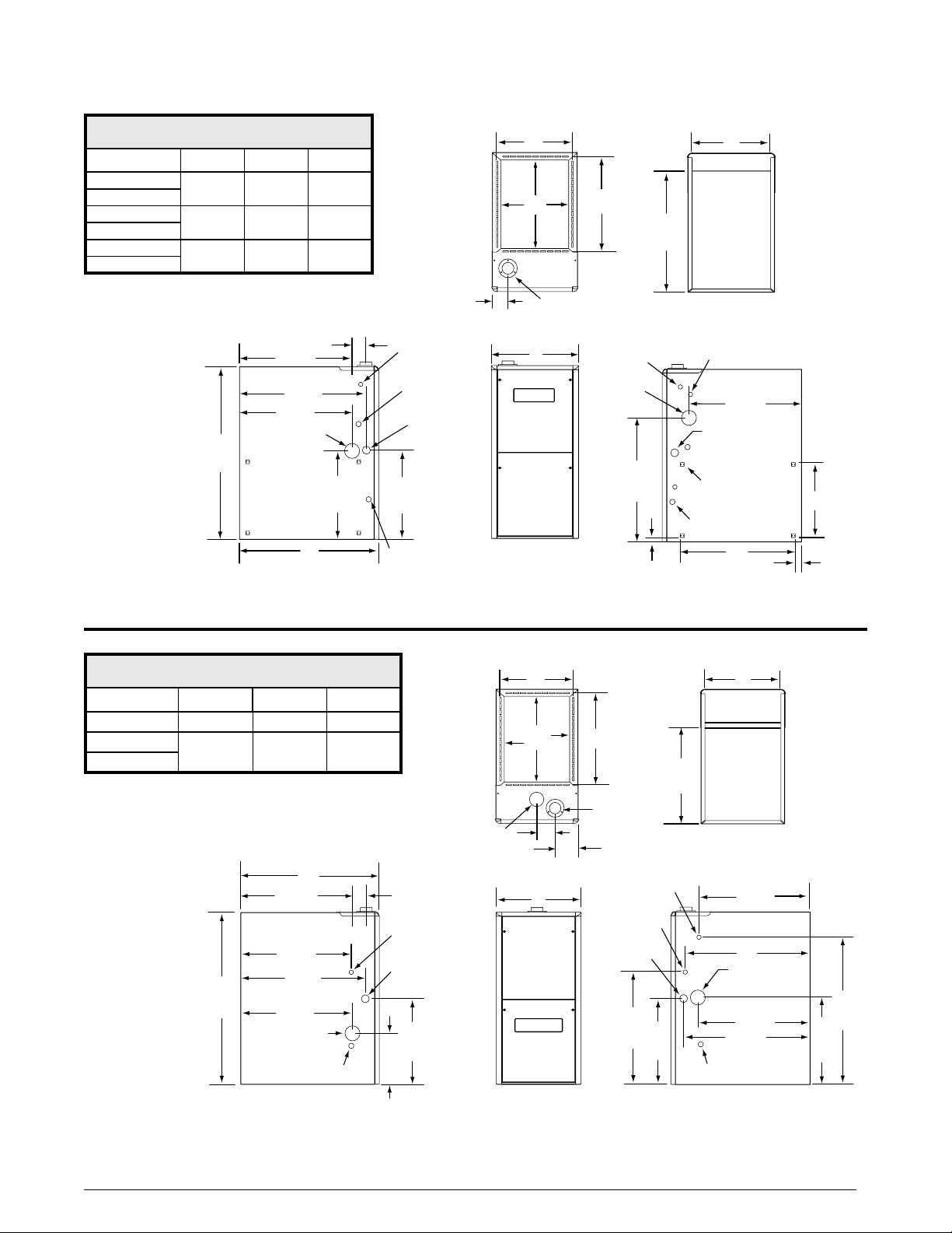
LEFT SIDE
RIGHT SIDE
TOP VIEW
BOTTOM VIEW
FRONT VIEW
J951X*U UPFLOW /
1 1/4
BOTTOM VIEW
TOP VIEW
LEFT SIDE
RIGHT SIDE
FRONT VIEW
HORIZONTAL FURNACES
MODEL #’S DIM. -A- DIM -B- DIM -C-
J951X038BU
J951X054BU
J951X072CU
J951X090CU
J951X108DU
J951X120DU
17 1/2 15 7/8 16 1/8
21 19 3/8 19 5/8
24 1/2 22 7/8 23 1/8
FIGURES & TABLES
B
FLANGES
19
23 1/2
C
Front Brace
Bottom
Panel
NOTE: Dimensions shown in inches.
2 3/4
22 1/2
25 3/8
22 1/2
Vent pipe
(Ø 3”)
34 1/2
17 1/4
28
Figure 29. J951X*U Cabinet Dimensions
J951X*D DOWNFLOW FURNACES
MODEL #’S DIM. -A- DIM. -B- DIM. -C-
J951X054BD 17 1/2 15 7/8 16 1/8
J951X072CD
J951X090CD
NOTE: Dimensions shown in inches.
21 19 3/8 19 5/8
28
22 1/2
22 1/4
25 1/2
T-stat
(Ø 7/8)
Electric
(Ø 7/8)
Gas
(Ø 1 5/8)
17 7/8
Condensate
(Ø 1 1/16)
2 3/4
Electric
(Ø 7/8)
Gas (Ø 1 5/8)
3 1/4
Flue
Combustion Air
A
B
FLANGES
3
A
T-stat
(Ø 7/8)
Vent pipe
(Ø 3”)
19
Combustion
Air
7 1/2
Electric
(Ø 7/8)
Gas
(Ø 1 5/8)
24 7/8
1
T-stat
(Ø 7/8)
Electric (Ø 7/8)
22 1/2
Gas (Ø 1 5/8)
4 Knockouts
(both sides)
Cond. (Ø 1 1/16)
23
C
Front
Brace
18 1/2
22 1/4
25
Vent pipe
(Ø 3”)
15
34 1/2
Cond. (Ø 1 1/16)
22 1/2
Vent pipe
(Ø 3”)
17 1/4
10 1/4
Figure 30. J951X*D Cabinet Dimensions
22 1/2
17 1/4
22 1/2
25 3/8
Cond. (Ø 1 1/16)
29 1/2
17 7/16
29
Page 30
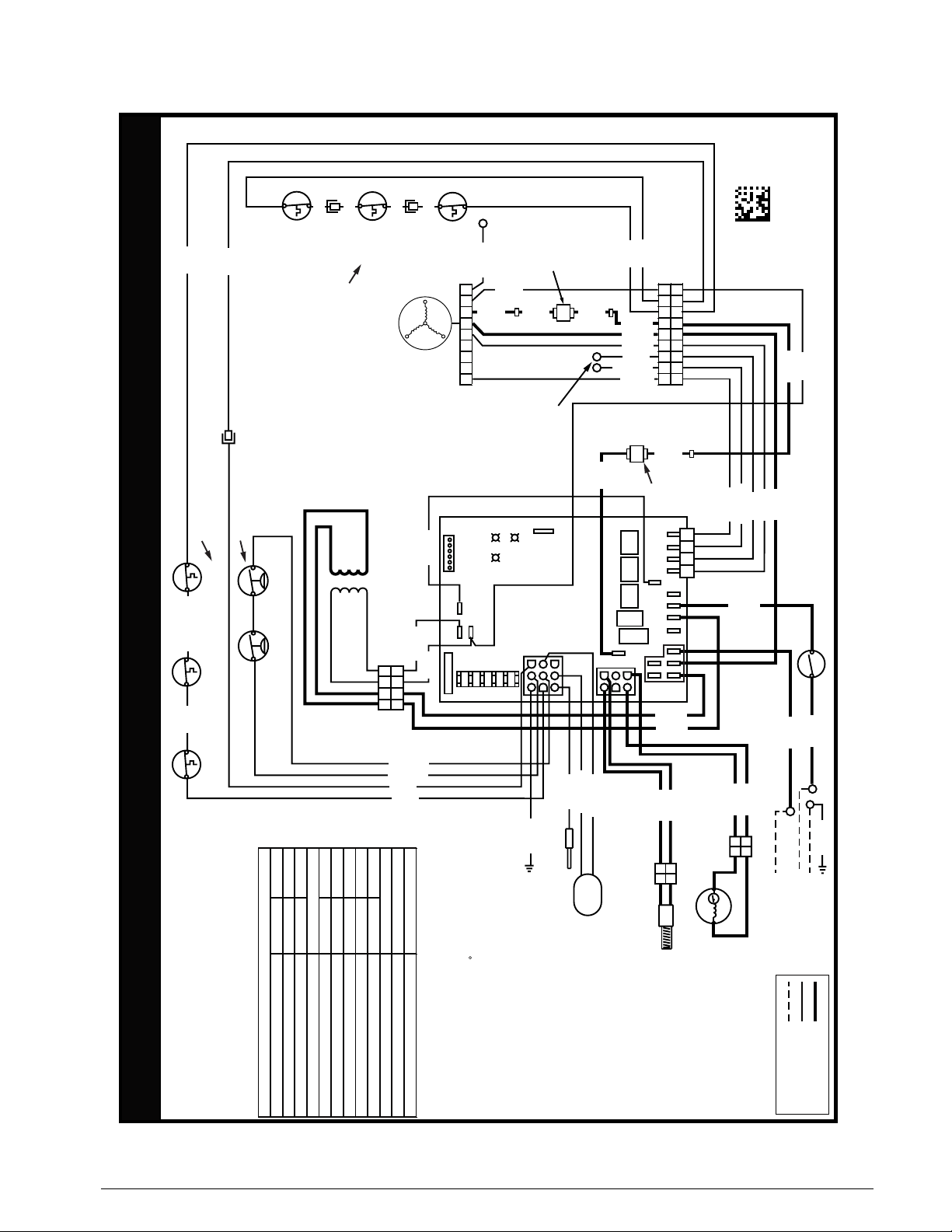
Electrical Information
IGNITOR
INDUCER
FLAME SENSOR
C
DOOR
SWITCH
R
GAS
VALV E
FLAME
ROLLOUT
SUPPLY
AIR LIMIT
PRESSURE
SWITCH
4
24 V
120 V
WHITE
BLACK
WHITE W/ BLK STRIPE
BLK W/ WHITE STRIPE
1234
1234
1
2
1
2
1
2
1
2
123456789
123456789
VENT
LIMIT
BLOWER
LIMIT
BLOWER
DECK
LIMIT
BLOWER
LIMIT
MOTOR
12345NLCG
NOTE: FOR
BLOWER
WIRING SEE
BLOWER TABLE
LITERAT URE
123
456
123
456
789
RCYGW
LOW
ML
MH
HIGH
EAC
L1
XFMR
HUM
COM
GREEN
YELLOW
RED
3 AMP FUSE
24V
R
C
TX
RX
W
COM
L1A
NEUTRALS
1234
24V
24V
MOTOR
CHOKE
BLACK
BLACK
FIELD WIRING
LEGEND:
LOW VOLTAGE
HIGH VOLTAGE
WIRING DIAGRAM
For Single Stage Furnaces
Refer to the Installation Instructions
provided with the furnace for the
proper heating and cooling speeds
for your application.
If any of the original wire as supplied with
the furnace must be replaced, it must be
replaced with wiring material having a
temperature of at least 105 C.
Use copper conductors only.
Diagnostic Description
Green LEDRed LED
Control Fault (No Power) OffOff
L1 / Neutral Polarity Fault FlashFlash
1 Hour Lockout
nOnOnoitarepO lamroN
Pressure Switch Closed Fault On Flash
Pressure Switch Open FaultFlash On
Open Limit Switch Fault FlashOff
Diagnostic Description
Low Flame Sensor Signal
Flame Present
FAULT CONDITIONS
Yellow LED
Continuous Flash
On
Alternating Flash
10284900
(Replaces 1027315A)
08/19
BLACK
BLACK
BLACK
BLACK
WHITE
BLACK
YELLOW
YELLOW
GREEN
BLUE
BLUE
BLUE
GREEN
BLUE
BLUE
BLUE
BLUE
BLUE
BLUE
GRAY
BLACK
WHITE
BLACK
BLUE
ORANGE
RED
RED
WHITE
BLACK
BLACK
WHITE
BLACK
BLUE
ORANGE
RED
BLACK
BLUE
BLUE
ORANGE
ORANGE
RED
RED
GRAY
GRAY
GREEN
BK/WH STRIPE
(ON SELECT
MODELS)
(ON SELECT
MODELS)
PRESSURE
SWITCH
(ON SELECT
MODELS)
WHITE (NEUTRAL)
BLACK 120 VAC
GROUND
(ON
SELECT
MODELS)
MOTOR
CHOKE
BLACK
BLACK BLACK
(ON SELECT
MODELS)
30
Figure 31. Wiring Diagram
Page 31
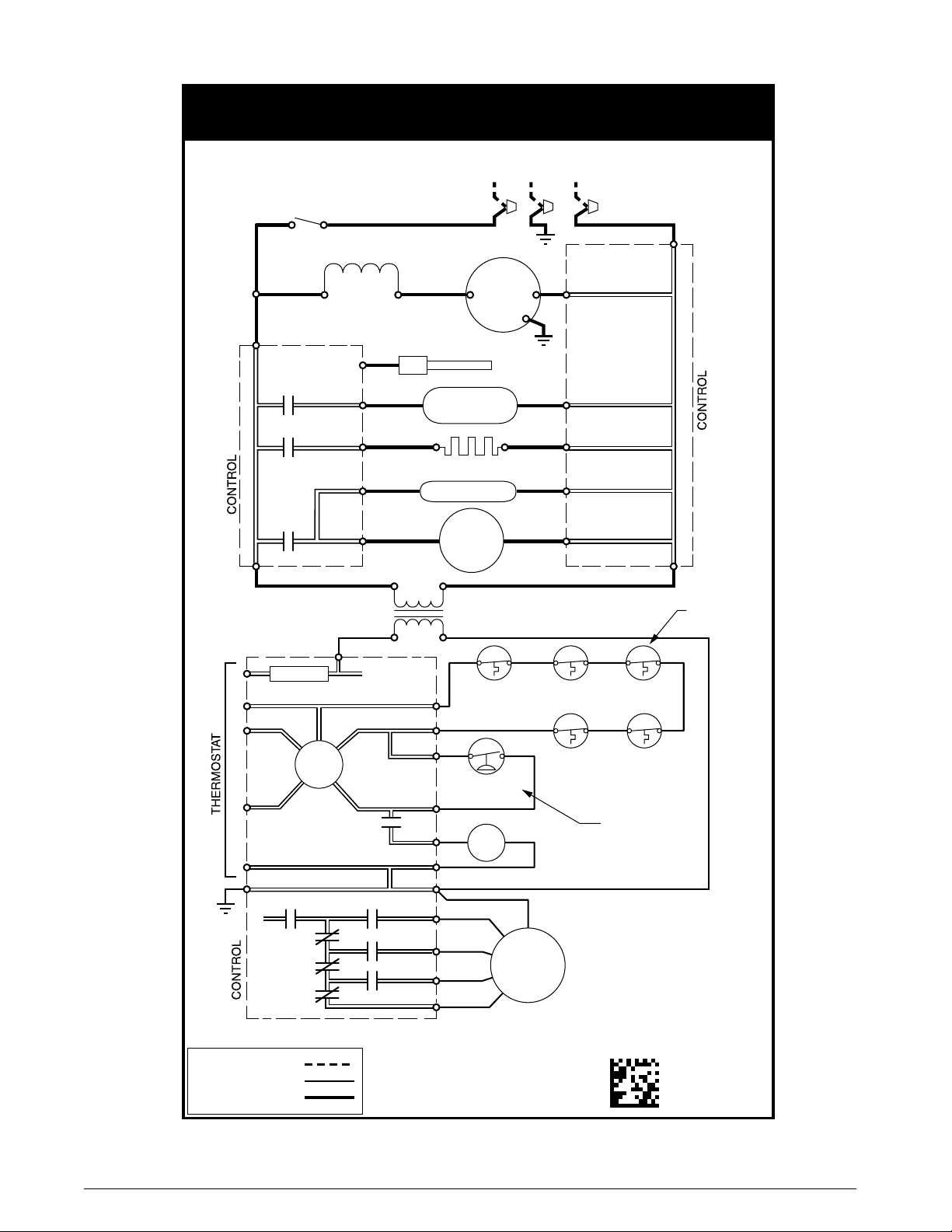
LADDER DIAGRAM
Single Stage Furnaces
DOOR
SWITCH
BLOWER
MOTOR
HUMIDIFIER
INDUCER
TRANSFORMER
L1
K4
K3
K2
XFORMER
CHOKE
(SOME MODELS)
P1-7
EAC
P2-3
HUM
P2-1
120 VAC
FLAME SENSOR
ELECTRONIC
AIR CLEANER
HOT SURFACE IGNITOR
L1 GND N
GND
GND
NEUTRAL
NEUTRAL
NEUTRAL
P2-6
NEUTRAL
P2-4
NEUTRAL
See Note
R
3A FUSE
W
G
Y
C
P1-9
K8
24V
GND
LEGEND:
FIELD WIRING
LOW VOLTAGE
HIGH VOLTAGE
MICRO
K5
K6
K7
24V
K5 HI
K6
K7
24 VAC
TO MOTOR
RELAYS
P1-8
P1-3
P1-6
P1-5
K1
P1-4
P1-2
COM
MED-HI
MED-LO
LO
SUPPLY AIR
LIMIT
PRESSURE
SWITCH
GAS
VLV
BLOWER
MOTOR
ROLL-OUT
LIMIT
BLOWER
LIMIT
SWITCH
VENT
LIMIT
BLOWER
DECK LIMIT
SWITCH
See Note
Quantity and types of
limits and switches
may vary with models.
(10299670)
1029967A
02/2020
Figure 32. Ladder Diagram
31
Page 32
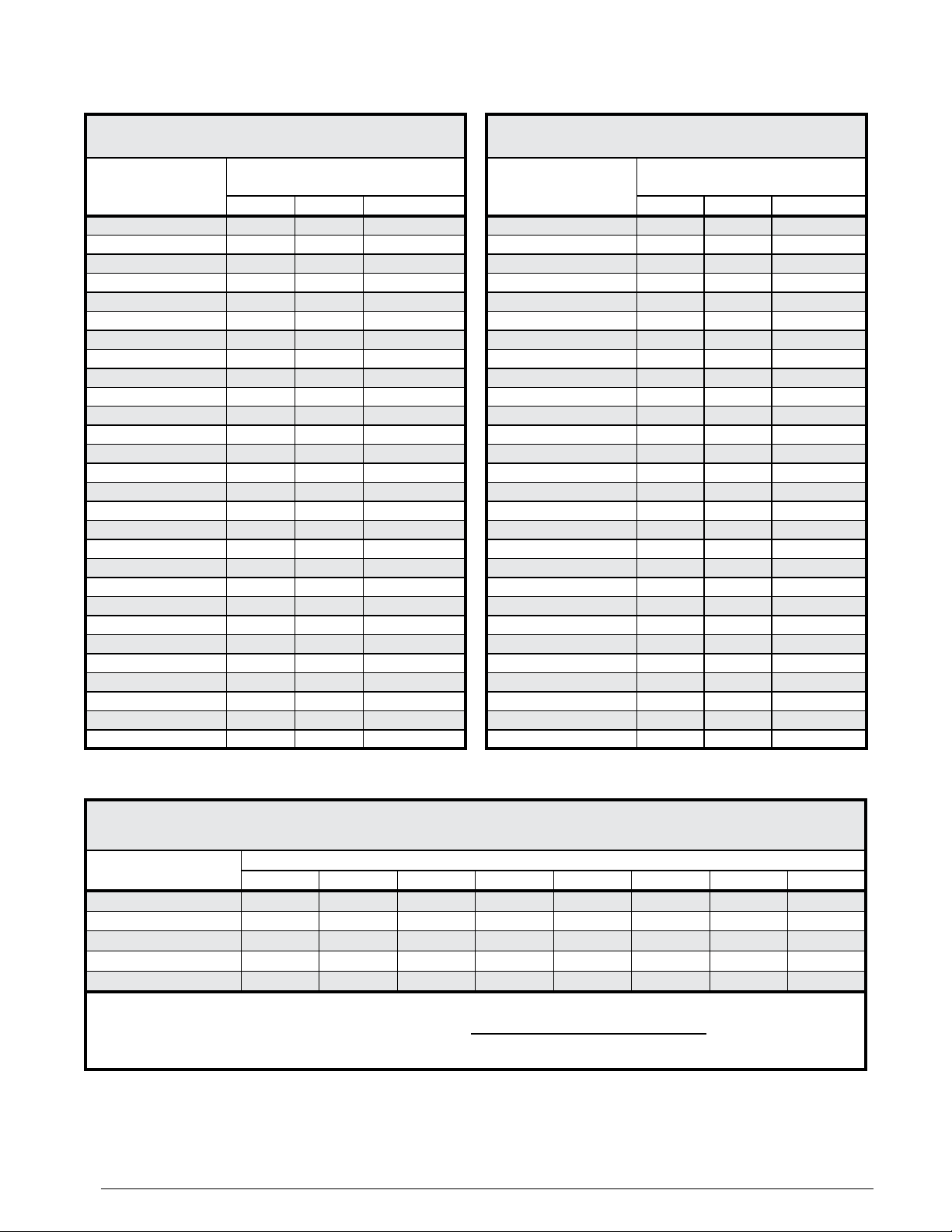
Gas Information
Cubic Feet Per Hour Required =
Input To Furnace (Btu/hr)
Heating Value of Gas (Btu/Cu. Ft.)
(CUBIC FEET PER HOUR)
TIME FOR
ONE REVOLUTION
(SECONDS)
10 360 1,800 3,600
12 300 1,500 3,000
14 257 1,286 2,571
16 225 1,125 2,250
18 200 1,000 2,000
20 180 900 1,800
22 164 818 1,636
24 150 750 1,500
26 138 692 1,385
28 129 643 1,286
30 120 600 1,200
32 113 563 1,125
34 106 529 1,059
36 100 500 1,000
38 95 474 947
40 90 450 900
42 86 429 857
44 82 409 818
46 78 391 783
48 75 375 750
50 72 360 720
52 69 346 692
54 67 333 667
56 64 321 643
58 62 310 621
60 60 300 600
62 58 290 581
64 56 281 563
GAS FLOW RATES
CUBIC FEET PER
REVOLUTION OF GAS METER
1 5 10
GAS FLOW RATES
(CUBIC FEET PER HOUR)
TIME FOR
ONE REVOLUTION
(SECONDS)
66 55 273 545
68 53 265 529
70 51 257 514
72 50 250 500
74 49 243 486
76 47 237 474
78 46 231 462
80 45 225 450
82 44 220 439
84 43 214 429
86 42 209 419
88 41 205 409
90 40 200 400
92 39 196 391
94 38 191 383
96 38 188 375
98 37 184 367
100 36 180 360
102 35 176 353
104 35 173 346
106 34 170 340
108 33 167 333
110 33 164 327
112 32 161 321
114 32 158 316
116 31 155 310
118 31 153 305
120 30 150 300
CUBIC FEET PER
REVOLUTION OF GAS METER
1 5 10
NOMINAL PIPE
DIAMETER (IN.)
1/2 130 90 75 65 55 50 45 40
3/4 280 190 150 130 115 105 95 90
1 520 350 285 245 215 195 180 170
1 1/4 1,050 730 590 500 440 400 370 350
1 1/2 1,600 1,100 890 760 670 610
The cubic feet per hour listed in the table above must be greater than the cubic feet per hour of gas flow required by the furnace. To determine
the cubic feet per hour of gas flow required by the furnace, divide the input rate of the furnace by the heating value (from gas supplier) of the gas.
32
Table 6. Gas Flow Rates
CAPACITY OF BLACK IRON GAS PIPE (CU. FT. PER HOUR)
FOR NATURAL GAS W/ SPECIFIC GRAVITY = 0.60
LENGTH OF PIPE RUN (FEET)
10 20 30 40 50 60 70 80
NOTE:
Table 7. Gas Pipe Capacities
Page 33
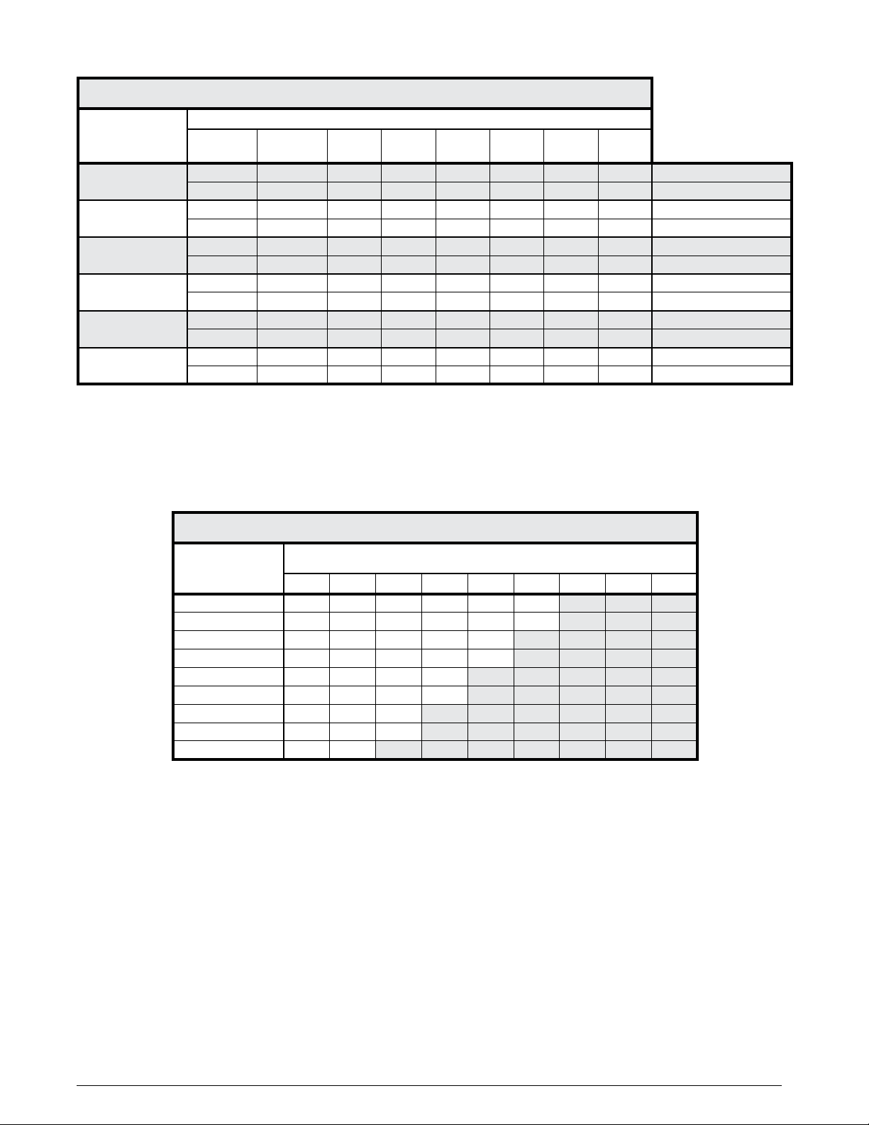
HIGH ALTITUDE DERATION – PROPANE GAS
ALTITUDE ABOVE
SEA LEVEL
0 to 1,999 FT
2,000 to 2,999 FT
3,000 to 4,999 FT
5,000 to 5,999 FT
6,000 to 7,999 FT
8,000 to 10,000 FT
INPUT (BTU)
38,000
(SC MODELS)
38,000
(SD MODELS)
54,000 72,000 90,000 108,000 118,000 120,000
56 60 56 56 56 56 55 55 ORIFICE SIZE
10.0 10.0 10.0 10.0 10.0 10.0 10.0 10.0 MANIFOLD PRESSURE
56 60 56 56 56 56 55 55 ORIFICE SIZE
9.0 9.0 9.0 9.0 9.0 9.0 9.0 9.0 MANIFOLD PRESSURE
56 60 56 56 56 56 55 55 ORIFICE SIZE
8.5 8.5 8.5 8.5 8.5 8.5 8.5 8.5 MANIFOLD PRESSURE
57 61 57 57 57 57 56 56 ORIFICE SIZE
10.0 8.5 10.0 10.0 10.0 10.0 10.0 10.0 MANIFOLD PRESSURE
57 61 57 57 57 57 56 56 ORIFICE SIZE
9.0 8.0 9.0 9.0 9.0 9.0 9.0 9.0 MANIFOLD PRESSURE
57 61 57 57 57 57 56 56 ORIFICE SIZE
8.5 7.5 8.5 8.5 8.5 8.5 8.5 8.5 MANIFOLD PRESSURE
Table 8. High Altitude Deration – Propane Gas
LOCAL HEATING VALUES FOR NATURAL GAS
ALTITUDE ABOVE
SEA LEVEL
650 700 750 800 850 900 950 1,000 1,050
BTU PER CUBIC FOOT
2,000 FT LOW LOW LOW LOW LOW LOW
3,000 FT LOW LOW LOW LOW LOW LOW
4,000 FT LOW LOW LOW LOW LOW
5,000 FT LOW LOW LOW LOW LOW
6,000 FT LOW LOW LOW LOW
7,000 FT LOW LOW LOW LOW
8,000 FT LOW LOW LOW
9,000 FT LOW LOW LOW
10,000 FT LOW LOW
HIGH HIGH HIGH HIGH HIGH HIGH HIGH
HIGH HIGH HIGH HIGH HIGH HIGH
HIGH HIGH HIGH HIGH HIGH HIGH
HIGH HIGH HIGH HIGH HIGH
HIGH HIGH HIGH HIGH HIGH
Table 9. Natural Gas Heating Values
HIGH HIGH HIGH
HIGH HIGH HIGH
HIGH HIGH HIGH HIGH
HIGH HIGH HIGH HIGH
33
Page 34
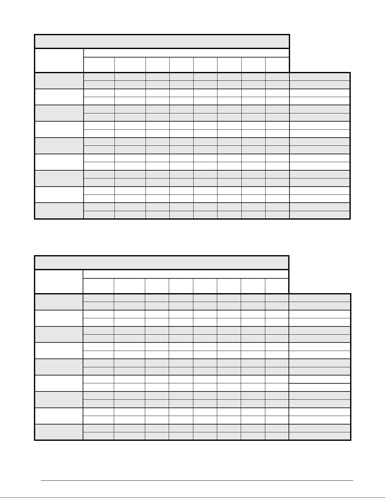
HIGH ALTITUDE DERATION – NATURAL GAS WITH HIGH HEATING VALUE
ALTITUDE ABOVE
SEA LEVEL
0 to 1,999 FT
2,000 to 2,999 FT
3,000 to 3,999 FT
4,000 to 4,999 FT
5,000 to 5,999 FT
6,000 to 6,999 FT
7,000 to 7,999 FT
8,000 to 8,999 FT
9,000 to 9,999 FT
INPUT (BTU)
38,000
(SC MODELS)
38,000
(SD MODELS)
54,000 72,000 90,000 108,000 118,000 120,000
45 51 47 47 47 47 46 45 ORIFICE SIZE
3.5 3.5 3.5 3.5 3.5 3.5 3.5 3.5 MANIFOLD PRESSURE
45 51 47 47 47 47 46 45 ORIFICE SIZE
3.0 3.2 3.2 3.2 3.2 3.2 3.2 3.3 MANIFOLD PRESSURE
45 51 47 47 47 47 46 45 ORIFICE SIZE
2.8 3.0 3.0 3.0 3.0 3.0 3.2 3.1 MANIFOLD PRESSURE
45 51 47 47 47 47 46 45 ORIFICE SIZE
2.7 2.8 2.8 2.8 2.8 2.8 2.8 2.9 MANIFOLD PRESSURE
45 51 47 47 47 47 46 45 ORIFICE SIZE
2.5 2.5 2.7 2.7 2.7 2.7 2.7 2.8 MANIFOLD PRESSURE
49 53 49 49 49 49 48 48 ORIFICE SIZE
3.5 3.5 3.5 3.5 3.5 3.5 3.5 3.5 MANIFOLD PRESSURE
49 53 49 49 49 49 48 48 ORIFICE SIZE
3.4 3.2 3.3 3.3 3.3 3.3 3.3 3.3 MANIFOLD PRESSURE
49 53 49 49 49 49 48 48 ORIFICE SIZE
3.2 3.0 3.0 3.0 3.0 3.0 3.0 3.0 MANIFOLD PRESSURE
49 53 49 49 49 49 48 48 ORIFICE SIZE
3.0 2.8 2.8 2.8 2.8 2.8 2.8 2.8 MANIFOLD PRESSURE
Table 10. High Altitude Deration – Natural Gas with HIGH Heating Value
HIGH ALTITUDE DERATION – NATURAL GAS WITH LOW HEATING VALUE)
ALTITUDE ABOVE
SEA LEVEL
0 to 1,999 FT
2,000 to 2,999 FT
3,000 to 3,999 FT
4,000 to 4,999 FT
5,000 to 5,999 FT
6,000 to 6,999 FT
7,000 to 7,999 FT
8,000 to 8,999 FT
9,000 to 9,999 FT
INPUT (BTU)
38,000
(SC MODELS)
38,000
(SD MODELS)
54,000 72,000 90,000 108,000 118,000 120,000
45 51 47 47 47 47 46 45 ORIFICE SIZE
3.5 3.5 3.5 3.5 3.5 3.5 3.5 3.5 MANIFOLD PRESSURE
45 51 47 47 47 47 46 45 ORIFICE SIZE
3.5 3.5 3.5 3.5 3.5 3.5 3.5 3.5 MANIFOLD PRESSURE
45 51 47 47 47 47 46 45 ORIFICE SIZE
3.1 3.4 3.3 3.3 3.3 3.3 3.3 3.4 MANIFOLD PRESSURE
45 51 47 47 47 47 46 45 ORIFICE SIZE
2.9 3.2 3.1 3.1 3.1 3.1 3.1 3.2 MANIFOLD PRESSURE
45 51 47 47 47 47 46 45 ORIFICE SIZE
2.8 3.1 2.9 2.9 2.9 2.9 2.9 3.1 MANIFOLD PRESSURE
45 51 47 47 47 47 46 45
2.6 2.9 2.8 2.8 2.8 2.8 2.8 2.9
ORIFICE SIZE
MANIFOLD PRESSURE
48 53 49 49 49 49 48 48 ORIFICE SIZE
3.3 3.5 3.4 3.4 3.4 3.4 3.4 3.5 MANIFOLD PRESSURE
48 53 49 49 49 49 48 48 ORIFICE SIZE
3.0 3.3 3.2 3.2 3.2 3.2 3.2 3.3 MANIFOLD PRESSURE
48 53 49 49 49 49 48 48 ORIFICE SIZE
2.8 3.1 2.9 2.9 2.9 2.9 2.9 3.1 MANIFOLD PRESSURE
34
Table 11. High Altitude Deration – Natural Gas with LOW Heating Value
Page 35
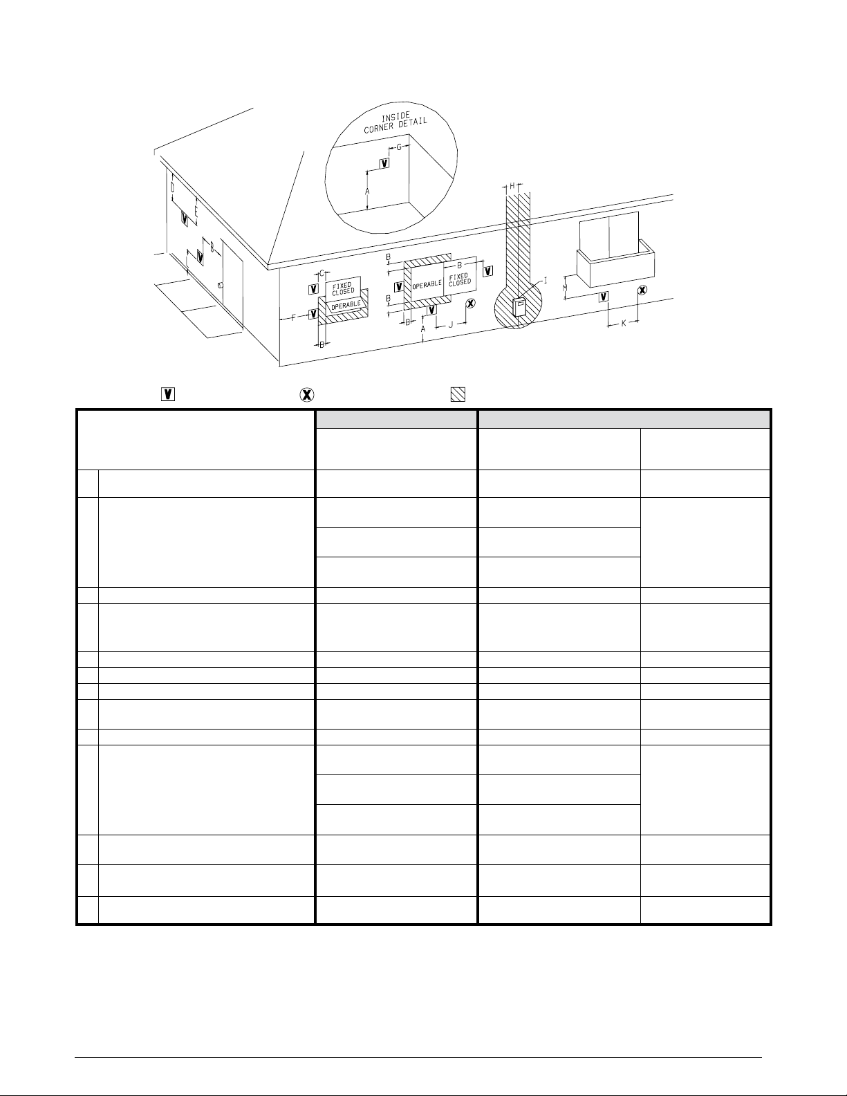
Venting Information
T PERMITTED
VENT TERMINAL
CLEARANCE LOCATION
Clearance above grade, veranda, porch, deck,
A =
balcony, or maximum expected snow level.
Clearance to window or door
B =
that may be opened.
C = Clearance to permanently closed window * * *
Vertical clearance to ventilated soffit located
above the terminal within a horizontal distance
D =
of 2 feet (61cm) from the center line of the
terminal.
E = Clearance to unventilated soffit. * * *
F = Clearance to outside corner. * * *
G = Clearance to inside corner. * * *
Clearance to each side of center line extended
H =
above meter/regulator assembly.
I = Clearance to service regulator vent outlet. 3 feet (1.83m) * *
Clearance to non-mechanical air supply inlet to
J =
building or the combustion air inlet to any other
appliance.
K = Clearance to mechanical air supply inlet. 6 feet (1.83m)
Clearance above paved sidewalk or driveway
L =
located on public property.
Clearance under veranda, porch, deck, or
M =
balcony.
AIR SUPPLY INLET
CANADIAN INSTALLATIONS
DIRECT VENT (2-PIPE) &
CONVENTIONAL VENT (1-PIPE)
appliances < 10,000 Btuh (3kW)
12 inches (30cm) for appliances
10,000 Btuh - 100,000 Btuh (30kW)
appliances > 100,000 Btuh (30Kw)
3 feet (91cm) within a height 15 feet
above the meter/regulator assembly
appliances < 10,000 Btuh (3kW)
12 inches (30cm) for appliances
10,000 Btuh - 100,000 Btuh (30kW)
appliances > 100,000 Btuh (30Kw)
FURNACES
12 inches (30cm) 12 inches (30cm) 12 inches (30cm)
6 inches (15cm) for
36 inches (91cm) for
* * *
6 inches (15cm) for
36 inches (91cm) for
c
7 feet (2.13m)
12 inches (30cm)
AREA WHERE TERMINAL IS NO
A
DIRECT VENT
(2-PIPE) FURNACES
6 inches (15cm) for
appliances < 10,000 Btuh (3kW)
9 inches (23cm) for appliances
10,000 Btuh - 50,000 Btuh (30kW)
12 inches (30cm) for
appliances > 50,000 Btuh (30Kw)
6 inches (15cm) for
appliances < 10,000 Btuh (3kW)
9 inches (23cm) for appliances
10,000 Btuh - 50,000 Btuh (30kW)
12 inches (30cm) for
appliances > 50,000 Btuh (30Kw)
3 feet (91cm) above if within
10 feet (3m) horizontally
d
US INSTALLATIONS
4 ft. (1.2m) below or to side
* *
4 ft. (1.2m) below or to side
3 ft. (91cm) above if within
* 7 ft. (2.13m)
* *
B
CONVENTIONAL VENT
(1-PIPE) FURNACES
of opening; 1 ft. (300mm)
above opening
of opening; 1 ft. (300mm)
above opening
10 feet (3m) horizontally
a: In accordance with the current CSA B149.1 Natural Gas and Propane Installation Guide Code
b: In accordance with the current ANSI Z223.1 / NFPA 54 Natural Fuel Gas Code
c: A vent shall not terminate directly above a sidewalk or paved driveway that is located between two single family dwellings and serves both dwellings.
d: Permitted only if veranda, porch, deck, or balcony is fully open on a minimum of two sides beneath the floor.
* For clearances not specified in ANSI Z223.1 / NFPA 54 or CSA B149.1, the following statement shall be included: “Clearance in accordance with local installation
codes, and the requirements of the gas supplier and the manufacturers installation instructions”
Table 12. Vent Termination Clearances
35
Page 36
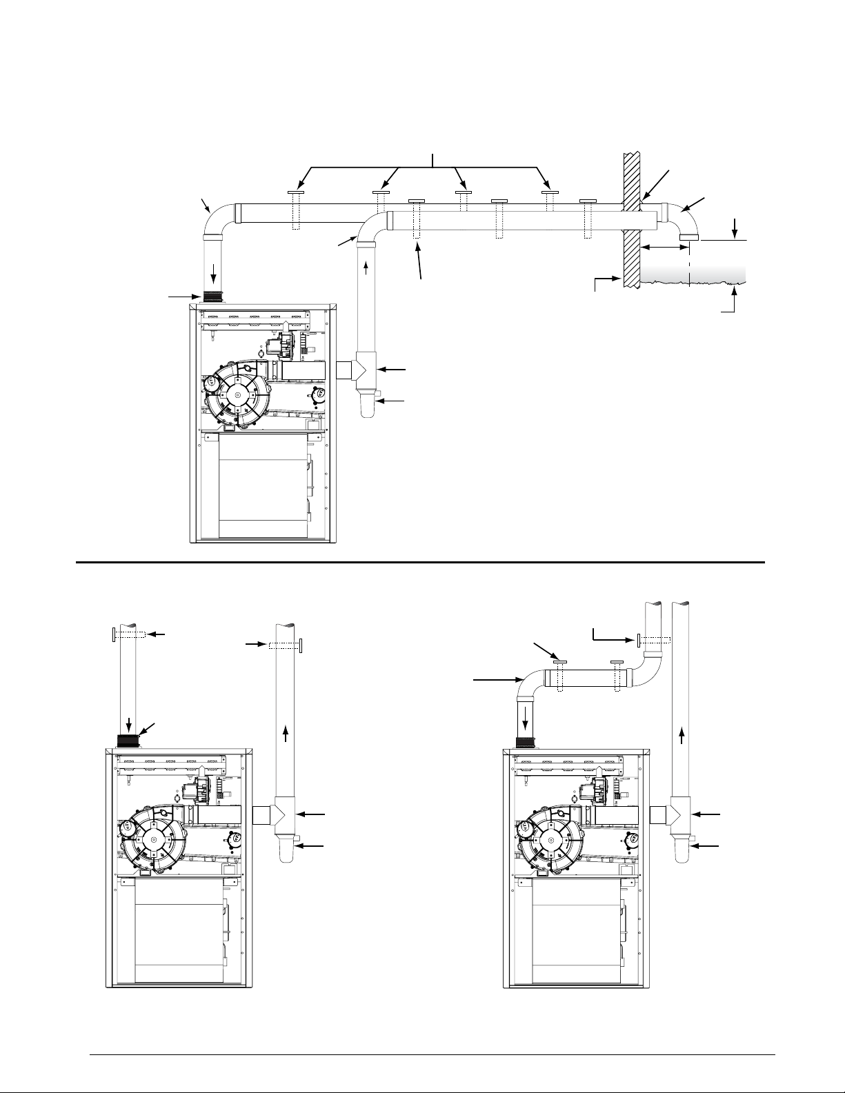
J951X*U & J951X*D Series
HORIZONTAL VENTING w/ 2-Pipes
(Upflo
VER
(Upflo
ap
w Furnace Shown)
90°
Elbow
See Table 2 for 2” PVC pipe
lengths (field supplied)
Clamps (Optional)
Coupling with 2 Hose
COMBUSTION AIR
90° Elbow
Straps or Other Suitable
Supports at minimum of 5 ft. Intervals
Upward Pitch - 1/4” per foot
(Flue Pipe)
First support placed as close
to furnace connection as possible
FLUE PIPE
PVC Tee
PVC Trap
Wall
Seal/Caulk
Around Pipes
at Building
90°
Elbow
7”
Normal
Snow Level
12” Min.
TICAL VENTING w/ 2-Pipes
w Furnace Shown)
Support System on
Vertical Rise
See Table 2 for 2” PVC pipe
lengths (field supplied)
Couplings with 2
COMBUSTION AIR
Hose Clamps (Optional)
FLUE PIPE
PVC Tee
PVC Trap
First Support as Close
to Furnace as Possible
90° Elbow
(both ends)
Support System on
Vertical Rise
COMBUSTION AIR
See Table 2 for 2” PVC pipe
lengths (field supplied)
FLUE PIPE
PVC Tee
PVC Tr
36
Figure 33. Horizontal & Vertical Venting
Page 37
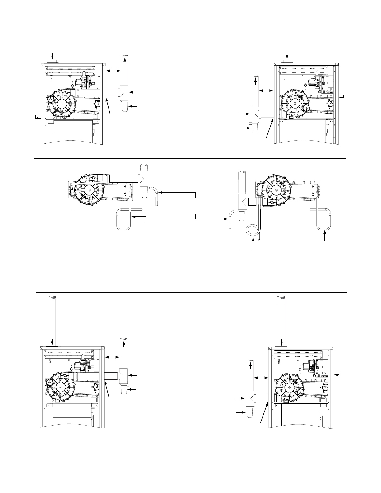
J951X*U SERIES UPFLOW - 1 PIPE OPTIONS
Plug
See VIEW A for drain line positions
See VIEW B for drain line positions
COMBUSTION
AIR
NOTE 5
Grommet
OPTION 1
See VIEW A for drain line positions
X
See
Rubber
FLUE PIPE
PVC Tee
PVC Trap
PVC Tee
PVC Trap
COMBUSTION
AIR
X
See
FLUE PIPE
NOTE 5
OPTION 2
Rubber
Grommet
See VIEW P for drain line positions
Plug
VIEW -A-
Field Supplied
Drain Line Attached
to PVC Trap
Inline Drain Tube
(Factory Supplied)
See NOTE 4
NOTES:
1. See Accessories section (page 17) for optional PVC Tee configurations and drainage options.
2. Drain lines must be trapped with a J-Trap or field supplied loop. Traps may be positioned inside or outside the cabinet. All drain
lines must be routed externally from the cabinet.
3. Inline drain is required only if “X” is greater than 6 feet.
4. Tubing needs to be cut to length and attached during unit installation.
5. Horizontal piping from inducer to flue pipe must be sloped 1/4” per foot to ensure drainage to PVC trapt.
Collector Box Drain
(Factory Equipped)
See NOTES 2 & 3
(Do Not Trap)
Inline Drain Tube
(Field Supplied)
See NOTE 3
VIEW -B-
J951X*U SERIES UPFLOW - 2 PIPE OPTIONS
COMBUSTION AIR
Collector Box Drain
(Factory Equipped)
See NOTES 2 & 3
COMBUSTION AIR
OPTION 3
X
See
Rubber
Grommet
FLUE PIPE
PVC Tee
PVC Trap
X
See
FLUE PIPE
NOTE 5
PVC Tee
PVC Trap
Rubber
Grommet
NOTE 5
Figure 34. Venting Options for Upflow Installations (J951X*U Series)
Plug
OPTION 4
37
Page 38
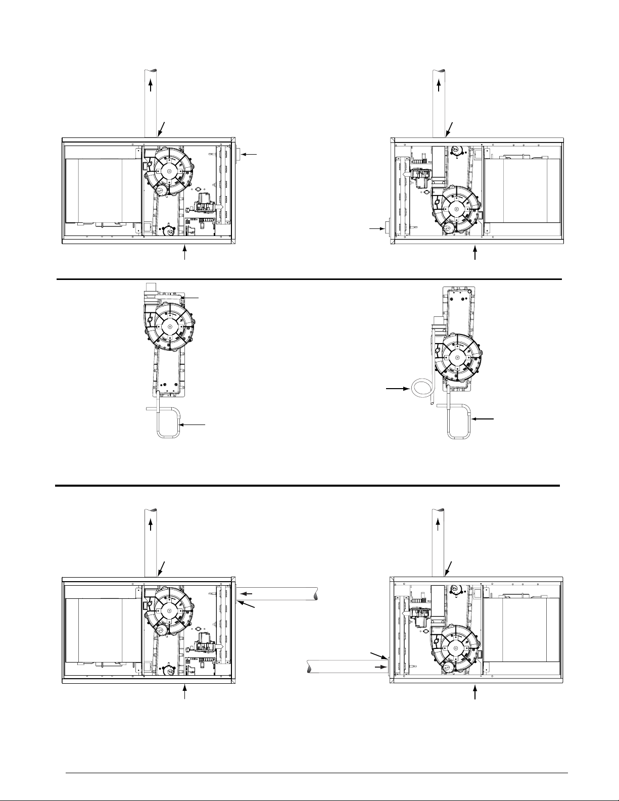
J951X*U SERIES HORIZONTAL RIGHT - 1 PIPE OPTION
Option
J951X*U SERIES HORIZONTAL LEFT - 1 PIPE OPTION
5
Rubber
Grommet
FLUE PIPE
COMBUSTION
AIR
COMBUSTION
AIR
Option
6
Rubber
Grommet
FLUE PIPE
See VIEW C for
drain line positions
Plug
(Factory Supplied)
Inline Drain
See NOTE 3
VIEW -C-
Inline Drain
(Factory Supplied)
See NOTE 2
Collector Box Drain
(Factory Equipped)
See NOTE 2
NOTES:
1. See Accessories section (page 17) for optional PVC Tee configurations and drainage options.
2. Drain lines must be trapped with a J-Trap or field supplied loop. Traps may be positioned inside or outside the cabinet. All drain lines must be routed externally
from the cabinet.
3. Tubing needs to be cut to length and attached during unit installation.
J951X*U SERIES HORIZONTAL RIGHT - 2 PIPE OPTION
Option
7
Rubber
Grommet
FLUE PIPE
J951X*U SERIES HORIZONTAL LEFT - 2 PIPE OPTION
See VIEW D for
drain line positions
FLUE PIPE
Plug
Rubber
Grommet
VIEW -D-
Collector Box Drain
(Factory Equipped)
See NOTE 2
Option
8
See VIEW C for
drain line positions
38
COMBUSTION AIR
Flange
Flange
COMBUSTION AIR
See VIEW D for
Plug
drain line positions
Plug
Figure 35. Venting Options for Horizontal Installations (J951X*U Series)
Page 39
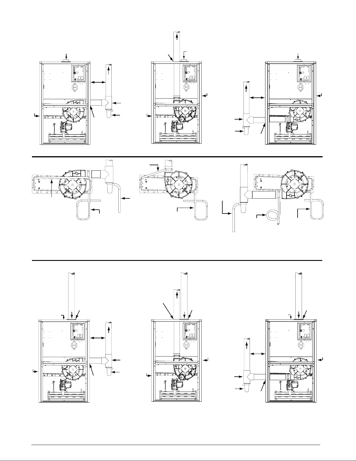
Plug
Plug
J951X*D SERIES DO
WNFLOW - 1 PIPE OPTIONS
See
or drain line positions
See VIEW G for drain line positions
See VIEW F for drain line positions
See VIEW E for drain line positions
J951X*D SERIES DO
Plug
Option
Plug
VIEW E for drain line positions See VIEW F for drain line positions
Inline Drain
(Factory Supplied)
See NOTE 4
NOTES
1. See Accessories section (page 17) for optional PVC Tee configurations and drainage options.
2. Drain lines must be trapped with a J-Trap or field supplied loop. Traps may be positioned inside or outside the cabinet. All drain lines must be routed externally
from the cabinet.
3. Inline drain is required only if “X” is greater than 6 feet.
4. Tubing needs to be cut to length and attached during unit installation.
5. Horizontal piping from inducer to flue pipe must be sloped 1/4” per foot to ensure drainage to PVC trap.
COMBUSTION
AIR
9
VIEW -E-
X
See
NOTE 5
Grommet
FLUE PIPE
Rubber
(Factory Supplied)
Collector Box Drain
(Factory Equipped)
See NOTE 2
PVC Tee
PVC Trap
Inline Drain
See NOTE 4
Field Supplied
Drain Line Attached
to PVC Trap
(Do Not Trap)
Rubber
Grommet
Option
10
Plug
Collector Box Drain
(Factory Equipped)
See NOTE 2
COMBUSTION
FLUE PIPE
VIEW -F-
AIR
Plug
Field Supplied
Drain Line Attached
to PVC Trap
(Do Not Trap)
PVC Tee
PVC Trap
X
See
FLUE PIPE
NOTE 5
Rubber
Grommet
See VIEW G f
Inline Drain
(Field Supplied)
See NOTES 2 & 3
COMBUSTION
AIR
Option
11
VIEW -G-
Collector Box Drain
(Factory Equipped)
See NOTE 2
Plug
Option
12
WNFLOW - 2 PIPE OPTIONS
Rubber
Grommet
Flange
COMBUSTION AIR
Flange
COMBUSTION AIR
FLUE PIPE
X
Option
Plug
13
Plug
PVC Tee
PVC Trap
X
See
FLUE PIPE
NOTE 5
Rubber
Grommet
See
NOTE 5
Rubber
Grommet
FLUE PIPE
PVC Tee
PVC Trap
Figure 36. Venting Options for Downflow Installations (J951X*D Series)
Plug
Option
14
Flange
COMBUSTION AIR
39
Page 40
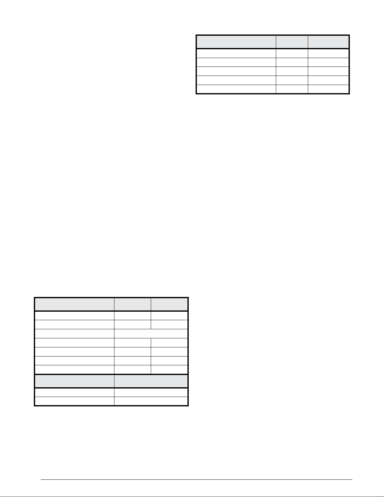
TROUBLESHOOTING
If the furnace fails to operate check the following:
• Is the thermostat operating properly?
• Are the blower compartment door(s) in place?
• Is the furnace disconnect closed?
• Has the circuit breaker tripped or the control board fuse
burned open?
• Is the gas turned on?
• Are any manual reset switches open?
• Is the filter dirty or plugged?
• Is the flame sensor coated? (Remove and clean with
steel wool. (Do not use emery cloth or sandpaper!)
• Is there blockage in the condensate drain switch? Also
verify that there is no double trapping of condensate.
• Is the secondary heat exchanger free of debris and
clogs?
• Is evaporator coil clean and free of debris (If applicable).
• Are all the LED’s on the furnace control board constantly
ON? If not, refer to
31 (page 30)
condition.
• Are all the LED’s on the motor control board constantly
ON? If not, refer to
The furnace will lock out after 5 failed attempts for ignition
and will try again every hour if the call for heat remains.
• If the Inducer Blower is operating, and items above have
been verified, check the Blower Limit Switch and reset if
necessary. See
for component location.
41)
• If the furnace operates when the Blower Limit Switch is
reset, contact a qualified service technician to identify
and repair the problem.
• If the furnace still doesn’t operate, check the Flame Roll-
out Switches and reset if necessary.
• If the furnace operates when the Flame Rollout Switch
is reset, contact a qualified service technician to identify
and repair the problem.
DIAGNOSTIC DESCRIPTION GREEN LED RED LED
Control Fault (No Power) Off Off
L1/Neutral Polarity Fault Flash Flash
1 Hour Lockout Alternating Flash
Normal Operation On On
Pressure Switch Closed Fault On Flash
Pressure Switch Open Fault Flash On
Open Limit Switch Fault Flash Off
Table 13 or the wiring diagram, Figure
or Figure 32 (page 31) to determine fault
Table 14 to determine fault condition.
IMPORTANT NOTE:
Figure 37 (page 41) or Figure 38 (page
DIAGNOSTIC DESCRIPTION RED LED GREEN LED
Control Fault (No Power) Off Off
Normal Operation On On
Motor Fault On Flash
Twin Fault (No Motor Fault) Flash On
Communications Fault Flash Flash
Table 14. Motor Control Board Fault Conditions
FURNACE COMPONENTS
The descriptions below are various functional components
that affect the operation and shutting down of this furnace.
Some of these components and their locations are shown
in
Figure 37 (page 41) or Figure 38 (page 41). If any
component of the furnace must be replaced, use only factory
authorized replacement parts specified in the Replacement
Parts List provided online.
Condensate Drain Switch: The Condensate Drain Switch
will shut down the furnace if the condensate drain from the
Collector Pan becomes clogged.
Blower Limit Switch: Prevents operation when blower is
not operational.
Flame Sensor: Verifies when a flame has carried over from
the igniter to the opposite end burner. If no flame is detected,
the furnace will shut down within 4 seconds.
Flame Roll-Out Switch: Verifies that the burner flames are
drawn into the heat exchanger tubes. If the burner flames are
not properly drawn into the heat exchanger, the flame roll-out
switch will close the gas valve and initiate the shutdown cycle.
Gas Valve: Controls the flow of gas to the burners. When the
gas valve is energized it automatically opens and regulates
the gas pressure in the manifold.
Inducer Assembly: Vents products of combustion to the
outside.
Pressure Switches: Verifies that the inducer is drawing
the combustion gases through the heat exchanger. The
pressure switch prevents furnace operation with excessive
flue/condensate blockage or improper inducer operation.
Supply Air Limit Switch: Prevents the air temperature
leaving the furnace from exceeding the maximum allowable
outlet air temperature.
DIAGNOSTIC DESCRIPTION YELLOW LED
Low Flame Sensor Signal Continuous Flash
Flame Present On
Table 13. Control Board Fault Conditions
40
Page 41
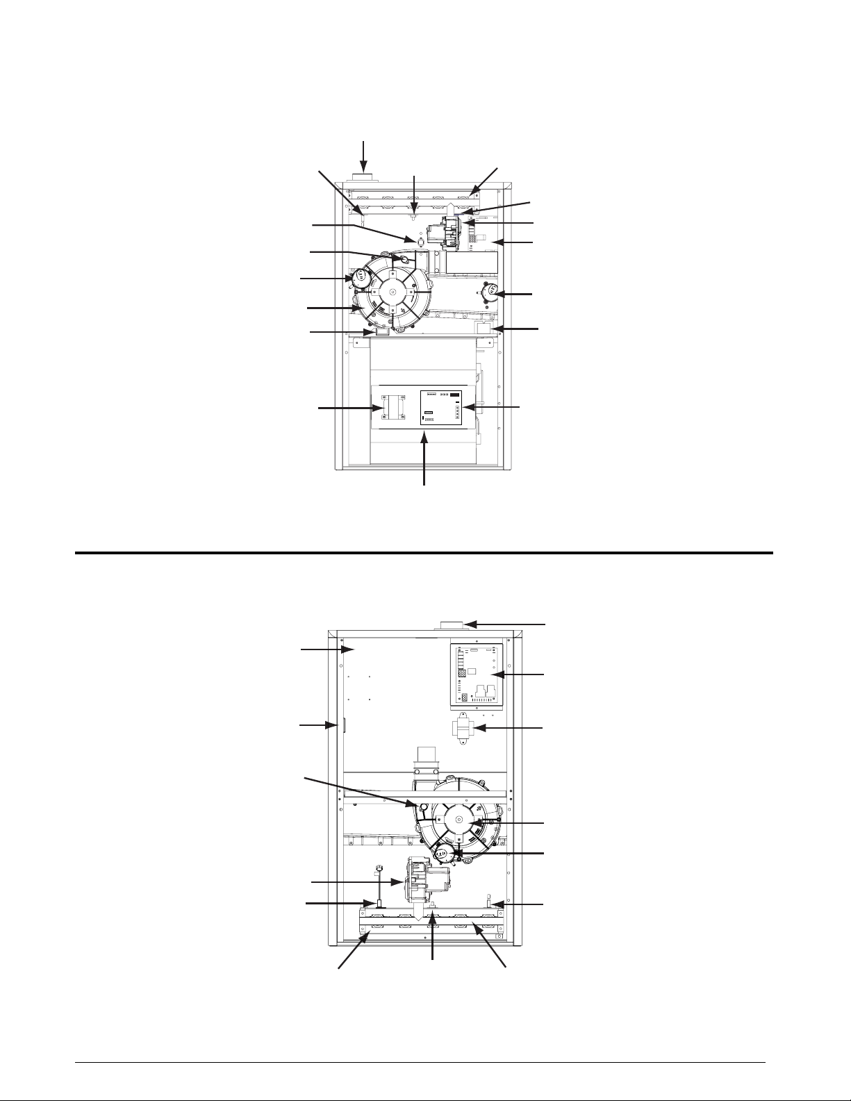
Assembly
Switch
(behind
Manifold
nace Control Board
DOWNFLOW FURNACE (J951X*D SERIES)
Flame
Furnace Control Board
Blower Assembly
Main Air Limit Switch
UPFLOW / HORIZONTAL FURNACE (J951X*U SERIES)
Sensor
Inducer Limit Switch
Pressure Switch
(Inducer)
Inducer Assembly
Blower Door Switch
Motor Choke
Finish
Flange
Roll-Out
Switch
Assembly
Igniter
Gas Valve
Pressure Switch
(Condensate)
Transformer
1234567
8
Motor Control Board
Figure 37. J951X*U Component Locations
Blower Assembly
blower panel)
Blower Door Switch
(behind blower panel)
Inducer Limit Switch
Gas Valve
Igniter
Finish Flange
Fur
Transformer
Inducer Assembly
Pressure Switch
Flame Sensor
Figure 38. J951X*D Component Locations
Burner
Roll-Out
Gas
41
Page 42

42
Page 43

43
Page 44
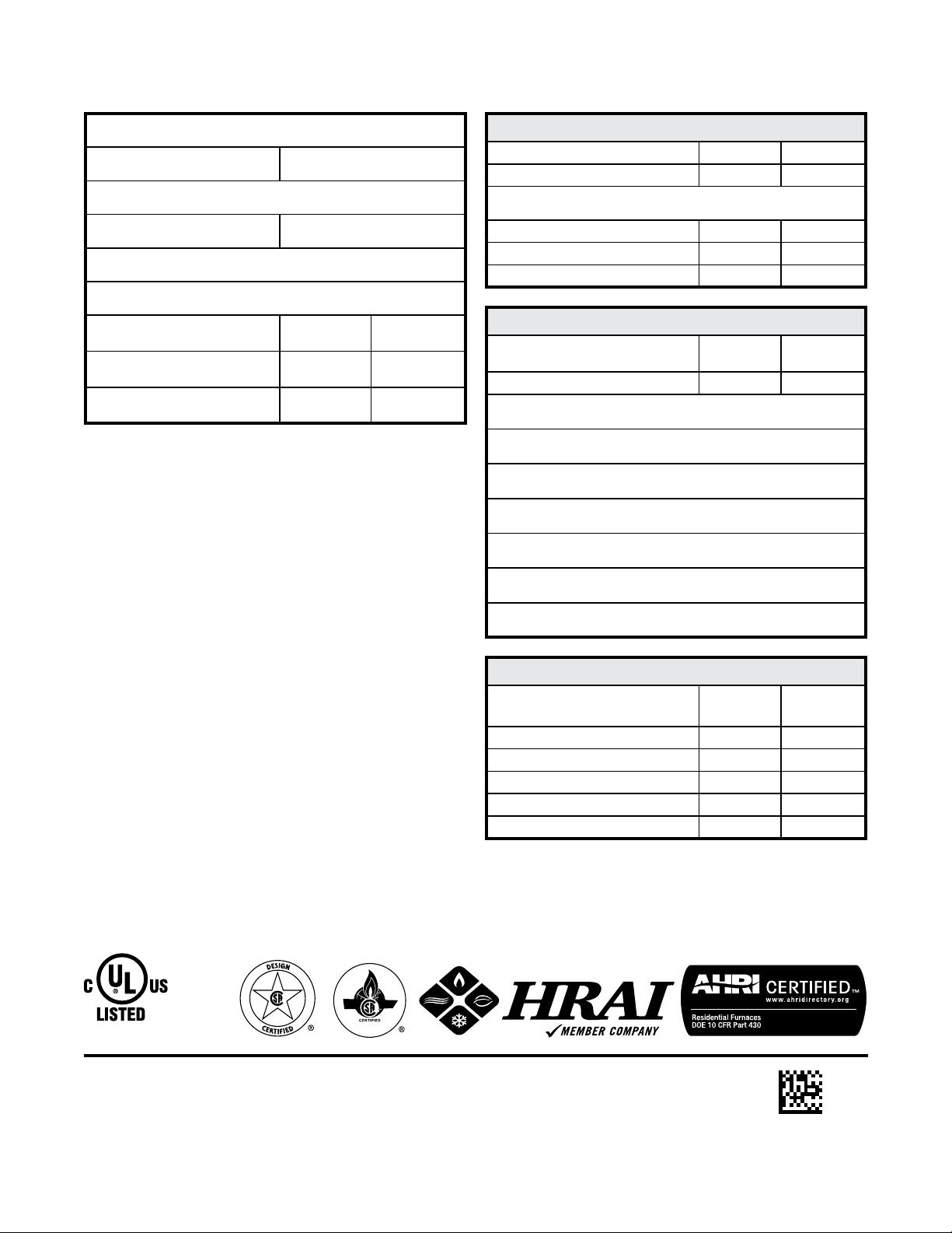
INSTALLATION CHECKLIST
INSTALLER NAME:
CITY: STATE:
INSTALLATION ADDRESS:
CITY: STATE:
UNIT MODEL #
UNIT SERIAL #
Minimum clearances per Figure 1
(page 5)?
Has the owner’s information been
reviewed with the home-owner?
Has the literature package been
left near the furnace?
YES NO
YES NO
YES NO
ATTENTION INSTALLERS:
It is your responsibility to know this product better than your customer.
This includes being able to install the product according to strict safety
guidelines and instructing the customer on how to operate and maintain
the equipment for the life of the product. Safety should always be the
deciding factor when installing this product and using common sense
plays an important role as well. Pay attention to all safety warnings and
any other special notes highlighted in the manual. Improper installation
of the furnace or failure to follow safety warnings could result in serious
injury, death, or property damage.
These instructions are primarily intended to assist qualified individuals
experienced in the proper installation of this appliance. Some local codes
require licensed installation/service personnel for this type of equipment.
Please read all instructions carefully before starting the installation.
Return these instructions to the customer’s package for future reference.
ELECTRICAL SYSTEM
Electrical connections tight? YES NO
Line voltage polarity correct? YES NO
Supply Voltage: ............................................................... VOLTS
Has the thermostat been calibrated? YES NO
Is the thermostat level? YES NO
Is the heat anticipator setting correct? YES NO
GAS SYSTEM
Gas Type: (circle one)
Gas pipe connections leak tested? YES NO
Gas Line Pressure: .......................................................... (in - W.C.)
Installation Altitude:............................................................(FT.)
Deration Percentage: .........................................................(%)
Furnace Input:....................................................................(Btuh)
Supply Air Temperature: ...................................................(° F)
Return Air Temperature: ...................................................(° F)
Temperature Rise: ............................................................(° F)
COMBUSTION AIR & VENTING SYSTEM
Natural
Gas
Propane
MH63349
(03/20)
G7SC
MGC2S
G7SD
G7SL
Is there adequate fresh air supply for
combustion and ventilation?
Vent free from restrictions? YES NO
Filter(s) secured in place? YES NO
Filter(s) clean? YES NO
Flue connections tight? YES NO
Is there proper draft? YES NO
YES NO
1027035A
(Replaces 10270350)
 Loading...