


User’s Manual of OWON Color Mixed Signal Digital Storage Oscilloscope
OWON
MSO5022
Portable Mixed Signal Digital Storage Oscilloscope
User Manual
1
WWW.OWON.COM.UA

User’s Manual of OWON Color Mixed Signal Digital Storage Oscilloscope
Copy Right in this Manual © Lilliput Company. All rights have been reserved.
The Lilliput’s products are under the protection of the patent rights in America and other
countries, including ones which have already obtained the patent rights and those which
are applying for. The information in this manual will replace all that in the materials
published originally.
Reserved will be the rights to change product specifications and prices.
Lilliput Company, 5F/B Area, Chuangxin Plaza, Software Park, Xiamen.
OWON is a trademark registered by Lilliput Company.
2

User’s Manual of OWON Color Mixed Signal Digital Storage Oscilloscope
WARRANTY
Lilliput warrants that this OWON brand product will be free from defects in materials and
workmanship for a period of three years (one year limited warranty applies to the accessories) from the
date of shipment. Lilliput warrants that software will operate substantially in accordance with its
functional specifications for 90 days and that it has been properly recorded on non-defective media.
Lilliput does not warrant that software will be error free or operate without interruption.
To obtain warranty service, contact your nearest Lilliput’s authorized service center or send the
product, with a description of the difficulty. Customer shall be responsible for shipping charges, freight,
insurance and proper packaging to prevent damage in transit. This warranty does not apply to defects
resulting from action of the user such as misuse, improper wiring, operation outside of specification,
improper maintenance or repair, or unauthorized modification. Lilliput shall not be liable for any
special, indirect, incidental or consequential damages or losses, including loss of data, whether arising
from breach of warranty or based on contract, tort reliance or any other theory, its total liability is
limited to repair or replacement of the product. All replaced parts, modules and products become the
property of Lilliput.
Lilliput authorized dealer shall extend this warranty on new and unused products to end-user
customers only but have no authority to extend a greater or different warranty on behalf of Lilliput.
Warranty support is available if product is purchased through a Lilliput authorized sales outlet or Buyer
has paid the applicable international price. Lilliput reserves the right to invoice Buyer for importation
costs of repair/replacement parts when product purchased in one country is submitted for repair in
another country.
Since some countries or states do not allow limitation of the term of an implied
warranty, or exclusion or limitation of incidental or consequential damages, the limitations
and exclusions of this warranty may not apply to every buyer. If any provision of this
Warranty is held invalid or unenforceable by a court of competent jurisdiction, such
holding will not affect the validity or enforceability of any other provision.
3
HTTP://WWW.OWON.COM.UA

User’s Manual of OWON Color Mixed Signal Digital Storage Oscilloscope
Table of Contents
General Safety Requirements.............................................................................................. 6
Safety Terms and Symbols................................................................................................... 7
General Characteristics of the MSO5022 Color Mixed Signal Digital Storage
Oscilloscope .........................................................................................................................9
Junior User Guidebook..................................................................................................... 10
Introduction to the Front Panel and the User's Interface of the MSO series Oscilloscope.... 11
Front panel ............................................................................................................................................. 11
Digital Storage Oscilloscope.........................................................................................................14
User interface introduction..................................................................................................................... 14
How to Carry on the General Inspection................................................................................................ 16
How to Carry on the Function Inspection ..............................................................................................16
How to Implement the Probe Compensation.......................................................................................... 17
How to Set the Probe Attenuation Coefficient ....................................................................................... 18
How to Use the Probe Safely..................................................................................................................19
How to Implement Auto-calibration ......................................................................................................19
Introduction to the Vertical System........................................................................................................ 20
Introduction to the Horizontal System.................................................................................................... 21
Introduction to the Trigger System......................................................................................................... 22
Logic Analyzer............................................................................................................................... 23
LA input connection............................................................................................................................... 23
User interface introduction..................................................................................................................... 23
How to acquire data................................................................................................................................24
How to observe and analyze the data .....................................................................................................24
Display systems...................................................................................................................................... 25
Trigger system........................................................................................................................................ 26
Threshold voltage system....................................................................................................................... 27
Sampling system ....................................................................................................................................27
Advanced User Guidebook................................................................................................29
Digital Storage Oscilloscope.........................................................................................................30
How to Set the Vertical System..............................................................................................................30
Implementation of Mathematical Manipulation Function...................................................................... 36
Application of VERTICAL POSITION and VOLTS/DIV Knobs......................................................... 37
How to Set the Horizontal system.......................................................................................................... 38
How to set trigger system....................................................................................................................... 41
How to Operate the Function Menu....................................................................................................... 47
How to Implement Sampling Setup .......................................................................................................48
How to Set the Display System.............................................................................................................. 50
How to Save and Recall a Wave Form................................................................................................... 54
How to Carry on the Auxiliary System Function Setting....................................................................... 56
4

User’s Manual of OWON Color Mixed Signal Digital Storage Oscilloscope
Do Self Cal (Self-Calibration)................................................................................................................ 57
SYS STAT (System State) .....................................................................................................................57
How to Conduct the Automatic Measurement .......................................................................................58
How to Carry on the Cursor Measurement............................................................................................. 60
Cursor Measurement .............................................................................................................................. 61
AUTOSET.............................................................................................................................................. 63
RUN/STOP ............................................................................................................................................64
U-DISK COPY....................................................................................................................................... 64
Logic analyzer................................................................................................................................65
How to set sampling system................................................................................................................... 65
How to set trigger system....................................................................................................................... 67
How to set threshold............................................................................................................................... 76
How to set display system...................................................................................................................... 78
How to set BUS...................................................................................................................................... 79
How to measure...................................................................................................................................... 81
How to save and recall ........................................................................................................................... 82
How to use USB Mass storage device to storage ................................................................................... 83
How to search......................................................................................................................................... 83
How to review setting info .....................................................................................................................87
How to use cursor measurement.............................................................................................................87
How to set Utility ...................................................................................................................................90
Demonstration ................................................................................................................... 91
Example 1: Measurement of Simple Signals............................................................................... 91
Example 2: Gain of the Amplifier in the Metering Circuit........................................................ 92
Example 3: Capture the Single Signal......................................................................................... 93
Example 4: Analyze the Details of a Signal................................................................................. 95
Example 5: Application of X-Y Function....................................................................................97
Example 6: Video Signal Trigger ................................................................................................. 98
F.A.Q ................................................................................................................................ 101
Appendix A: T echnical Specifications............................................................................ 102
Digital Storage Oscilloscope.......................................................................................................102
Logic analyzer.............................................................................................................................. 104
Appendix B: Enclosure ................................................................................................... 106
Appendix C: Maintenance, Cleaning and Repairing..................................................... 106
Appendix D: Battery Using Guide.................................................................................. 107
5

User’s Manual of OWON Color Mixed Signal Digital Storage Oscilloscope
General Safety Requirements
Before any operations, please read the following safety precautions to avoid any
possible bodily injury and prevent this product or any other products connected
from damage. In order to avoid any contingent danger, this product is only used
within the range specified.
Only the qualified technicians can implement the maintenance.
Prevent the Fire or Bodily Injury.
Use the proper power line. Only use the power cord specially provided for this product
or that has been approved to be used in this user state.
Connect or Disconnect Correctly. When the probe or testing wire is connected to the
power lead, please do not connect and disconnect the probe or testing wire at random.
Product Grounded. This product is grounded through the power lead grounding
conductor. In order to prevent any electric shocking, the grounding conductor must be
connected to the ground. It requires guarantee that this product has been already grounded
correctly before any connection with its input or output terminal.
Connect the probe correctly. The grounding end of the probe corresponds to the
grounding phase. Please don't connect the grounding end to the positive phase.
Pay attention to the nominal values of all terminals. In order to prevent any fire or
electric shock risks, please pay attention to all the nominal values and marks of this
product. Before implement any connections for this product, please read the user's manual
of this product to understand the information about the rated values further.
Do not make any operations without the instrument cover installed. If the cover or
panel has already been removed, please don't operate this product.
Use the proper fuse. Only the fuse complying with the specified type and nominal value
for this product can be used.
Avoid touching any exposed circuit. When the product is on power, please don't touch
the uncovered contacts and parts.
Please don't make any operations while there is an uncertain fault emerged. If
suspecting damage to this product, please contact the qualified maintenance personnel for
check.
Keep a good ventilation condition. Please consult the detailed installation instruction in
the user's manual so that this product can be erected correctly, keeping it under a good
ventilation condition.
Please do not make any operations in a moist environment.
Please do not make any operates in an explosive environment.
Keep the products surface clean and dry.
6
User’s Manual of OWON Color Mixed Signal Digital Storage Oscilloscope
Safety Terms and Symbols
Terms in this manual. The following terms may appear in this manual:
Warning. A warning statement indicates the conditions and actions which may
endanger the life safety.
Note. A note statement indicates the conditions and actions which may cause
damage to this product or other property.
Terms on the product. The following terms may appear on this product:
Danger: It indicates that there may be an immediate injury to you when you encounter
this mark.
Warning: It indicates that there may not be an immediate injury to you when you
encounter this mark.
Note: It indicates that there may be damage to this product or other property.
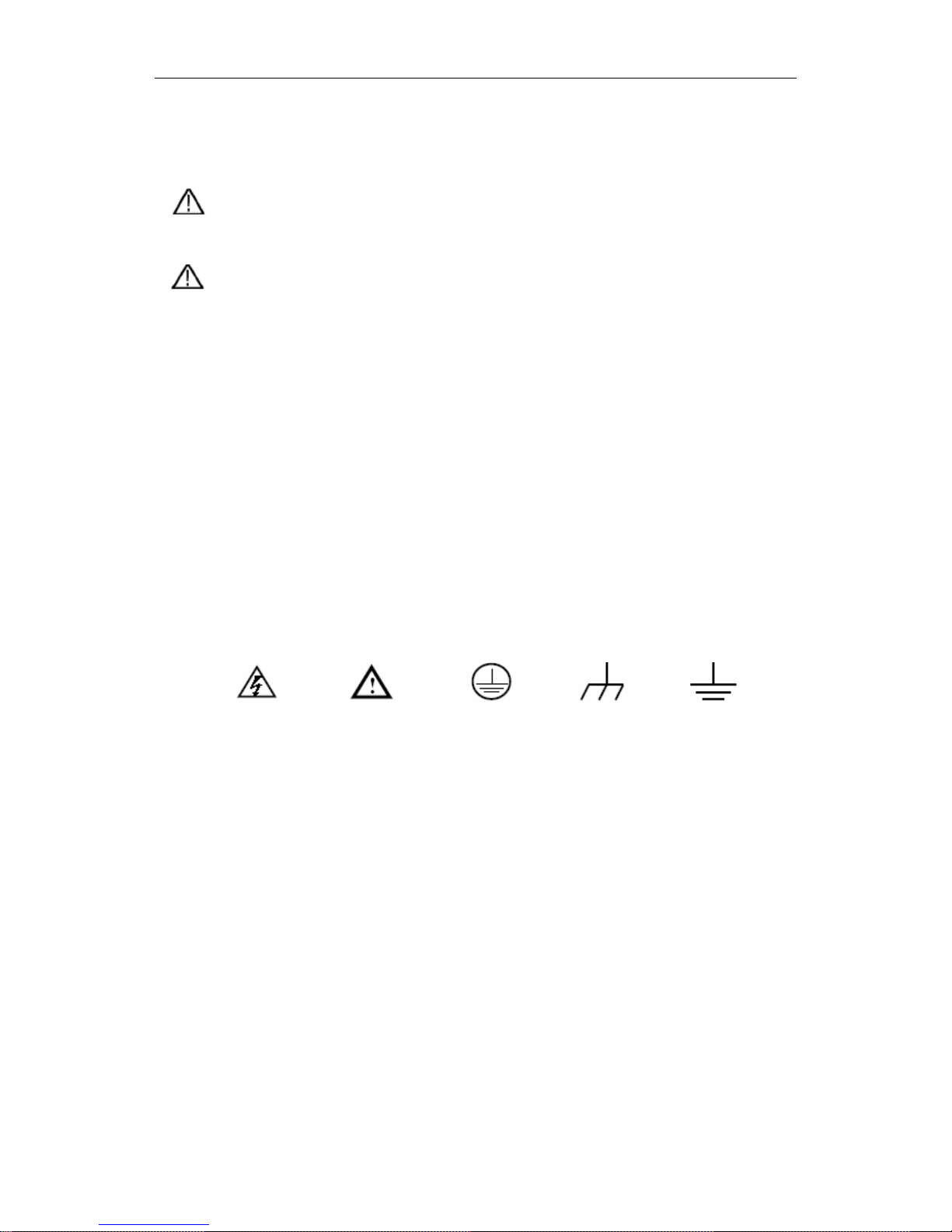
Symbols on the product. The following symbol may appear on the products:
DANGER:
Hi
gh Voltage
Refer to the
Manual
Protective
Conductor
Terminal
Chassis
Ground
Earth (ground)
Terminal
7

User’s Manual of OWON Color Mixed Signal Digital Storage Oscilloscope
To avoid body damage and prevent product and connected equipment dam. This product
can only be used in the specified applications. Carefully read the following safety
information before using the test tool.
Warning:
When use BC(battery charge) as power supply, to avoid fire or electrical shock if
a test tool input is connected to more 42V peak (30Vrms) or on circuits of more than
4800VA:
z Only use accessory insulated voltage probes, test lead
z Before use, inspect oscilloscope probes, accessories for mechanical damage
and replace when damage.
z Remove all probes, test leads and accessories that are not in use.
z Remove computer data line
z Do not apply input voltages above the rating of the instrument Use caution
when using 1:1 test leads because the probe tip voltage will be directly
transmitted to the oscilloscope.
z Do not use exposed metal BNC or banana plug connectors
z Do not insert metal objects into connectors.
8

User’s Manual of OWON Color Mixed Signal Digital Storage Oscilloscope
General Characteristics of the MSO5022
Color Mixed Signal Digital Storage
Oscilloscope
Digital Storage Oscilloscope
z With the bandwidth of 25M;
z Record length of 5,000 points for each channel;
z Sampling rates of 100MS/s for each channel;
z Reading-out with the cursor;
z Five automatic measurement functions;
z Color liquid crystal display of high resolution and high contrast with adjustable
back light;
z Storage and call-out of waveforms;
z Automatic setting function provided capable of fast setting;
z Multiple-waveform calculation function;
z Implementation of detecting the average and peak values of the waveform;
z Digital real-time oscilloscope;
z Edge and video triggering function;
z RS232 or USB communication ports;
z Different continuous displaying time;
z User interface in two languages for the user’s choice.
Logic Analyzer
z 16 Optional input channel;
z 100MHz/S max sampling rates for each channel;
z 4M max Storage for each channel;
z Plenty of trigger Mode;
z Convenient data measurement & data search;
z Freely setting of all kinds of threshold level;
9

User’s Manual of OWON Color Mixed Signal Digital Storage Oscilloscope
Junior User Guidebook
This chapter deals with the following topics mainly:
Digital Storage Oscilloscope
z Introduction to the front panel and the user’s interface of the MSO
series oscilloscope
z How to carry on the general inspection
z How to carry on the function inspection
z How to make a probe compensation
z How to set the probe attenuation coefficient
z How to use the probe safely
z How to implement an auto-calibration
z Introduction to the vertical system
z Introduction to the horizontal system
z Introduction to the trigger system
Logic Analyzer
z User interface introduction
z How to acquire data
z How to observe and analyze the data
z Display systems
z Trigger system
z Threshold voltage system
z Sampling system
10
User’s Manual of OWON Color Mixed Signal Digital Storage Oscilloscope
Introduction to the Front Panel and the User's Interface of
the MSO series Oscilloscope
When you get a new-type oscilloscope, you should get acquainted with its front panel at
first and the MSO series mixed digital storage oscilloscope is no exception. This chapter
makes a simple description of the operation and function of the front panel of the MSO
series mixed oscilloscope, enabling you to be familiar with the use of the MSO series
mixed oscilloscope in the shortest time. The MSO series mixed oscilloscope offers a
simple front panel with distinct functions to users for their completing some basic
operations, in which the knobs and function pushbuttons are included. The knobs have the
functions similar to other oscilloscopes. The 5 buttons in the column on the right side of
the display screen are menu selection buttons (defined as F1 to F5 from top to bottom
respectively), through which, you can set the different options for the current menu. The
other pushbuttons are function buttons, through which, you can enter different function
menus or obtain a specific function application directly.
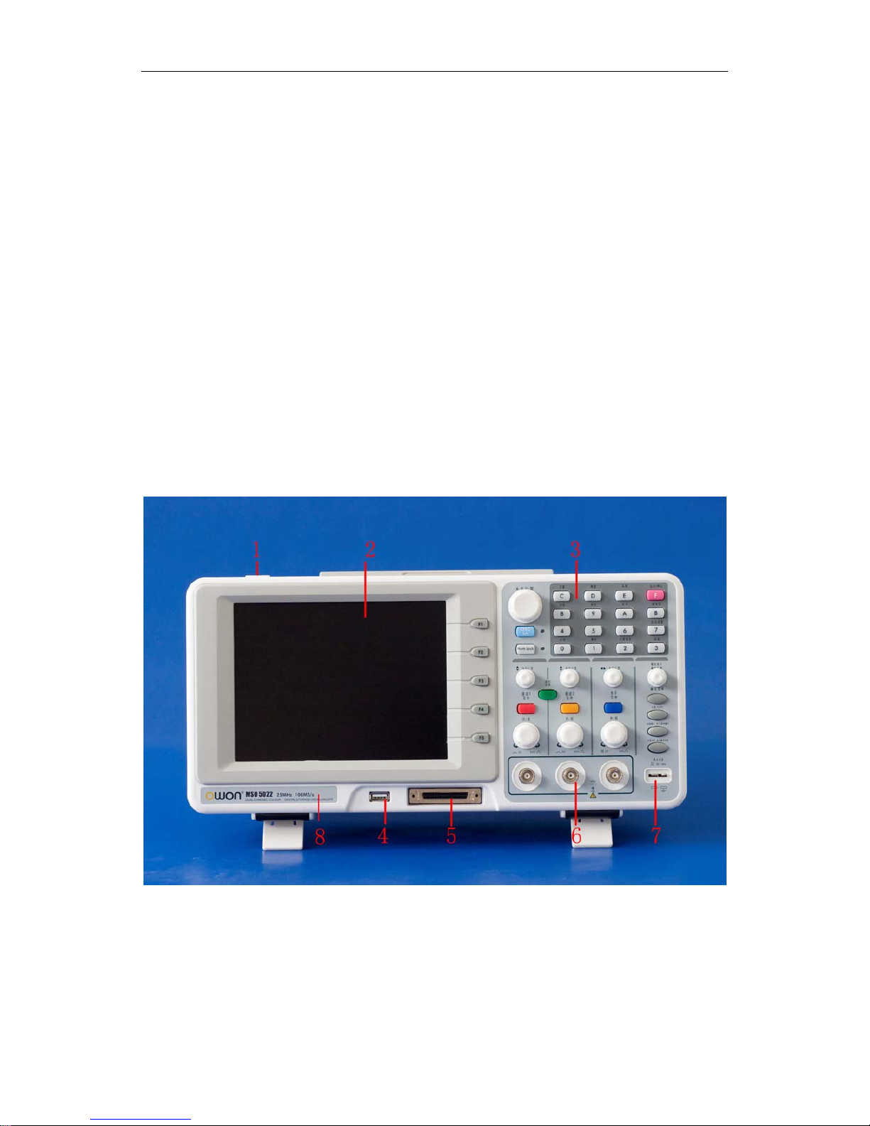
Front panel
Fig 1: Front panel overview
1、 Power on/off
2、 Display area
3、 Control (key and knob) area
4、 U slot
5、 LA signal input
11
User’s Manual of OWON Color Mixed Signal Digital Storage Oscilloscope
6、 DSO signal input
7、 Measurement signal output
8、 Power and charging indication: Green light indicate AC supply and battery full
charged; yellow light indicate under charging
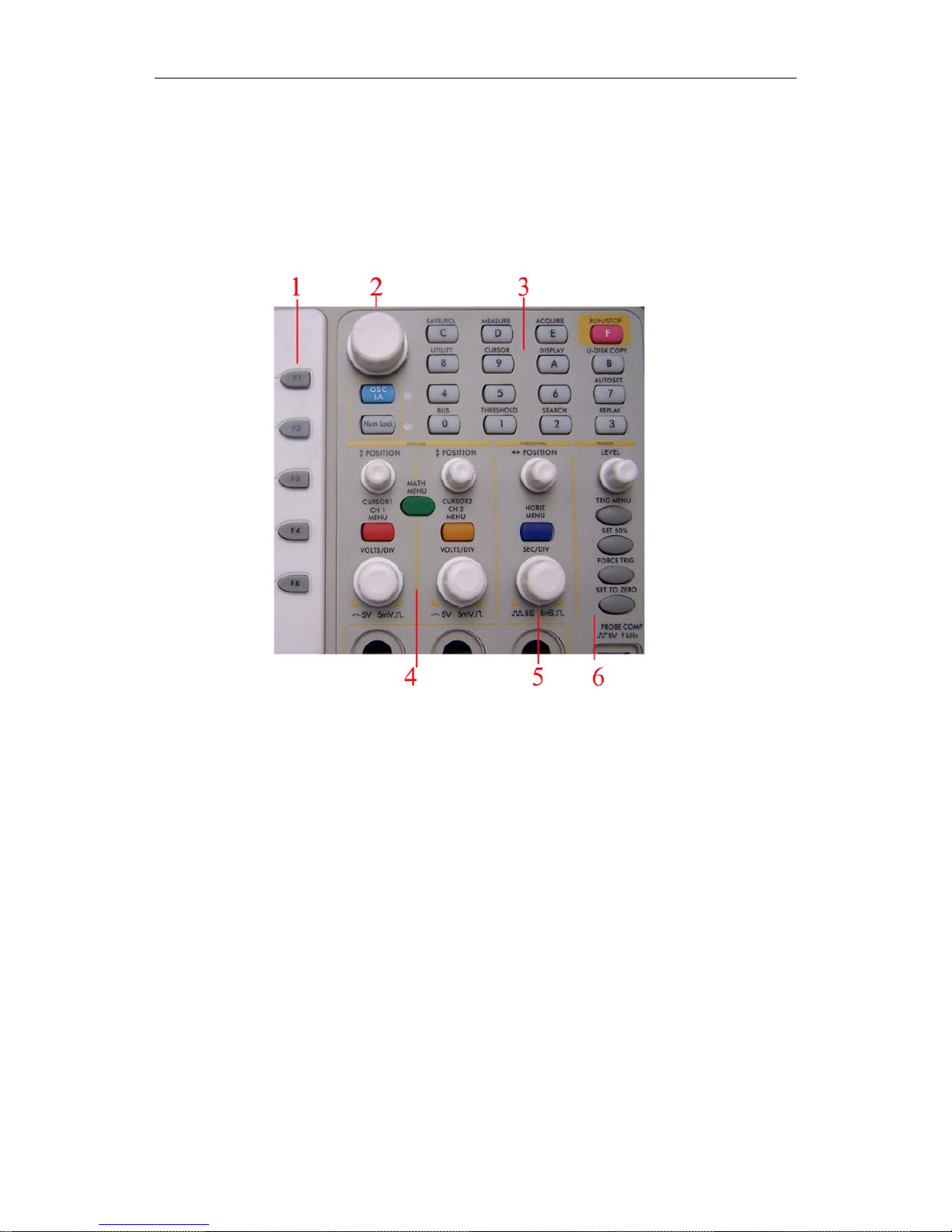
Fig 2: Keys Overview
1、Menu option setting: F1~F5
2、Switch
Switch includes two keys and one knob. Press “OSC/LA” to switch between DSO and
LA.
For DSO “cursor” knob and “info” key are idle.
For LA, “cursor” knob to adjust current cursor position and “info” key to loading
setting info for acquired waveform and current waveform.
3、Function key area
For DSO 0~6 keys are idle and 7~F refer to different DSO function menu.
For LA, 3.4.5.6.7 refers to figure and other keys refer to digit or function menu.
4、Vertical control area
It’s including 3 keys and 4 knobs.
For DSO: “CH1 menu” and “CH2 menu” correspond to setting menu in CH1 and CH2,
“Wave Math” key refer to math menu, two “Vertical position” knob control the vertical
12

User’s Manual of OWON Color Mixed Signal Digital Storage Oscilloscope
position of CH1. CH2, and two “Volts/Div” knob control voltage scale of CH1, CH2.
For LA, “CH1 menu”, “CH2 menu”, “Wave math” keys and “CH2 Volts/Div” knob
are idle. “CH1 Vertical”, “CH2 Vertical” to adjust the M1, M2 position in Cursor menu
when cursor display is on. “CH1 Volts/Div”
5、Horizontal control area with 2 knob and 1 key.
For DSO, “Horizontal position” knob control trigger position, “Volts/Div” control
time base, “Horizontal menu” key refer to horizontal system setting menu.
For LA, “Horizontal menu” key is idle. “Horizontal position” knob to adjust the
position of value displayed currently quickly. “Sec/Div” knob to adjust value resolution
displayed currently.
6、Trigger control area with 4 keys and 1 knob.
For DSO, “Trig adjust” knob is to adjust trigger voltage. Other four keys refer to
trigger system setting.
For LA, “Force trig” key is idle. “Trig menu” refer to trigger menu control. “Trig
adjust” knob to adjust trigger position in memory, “SET 50” is to set trigger position as
50% and “SET Zero” set trigger position as 0.
13
User’s Manual of OWON Color Mixed Signal Digital Storage Oscilloscope
Digital Storage Oscilloscope
User interface introduction
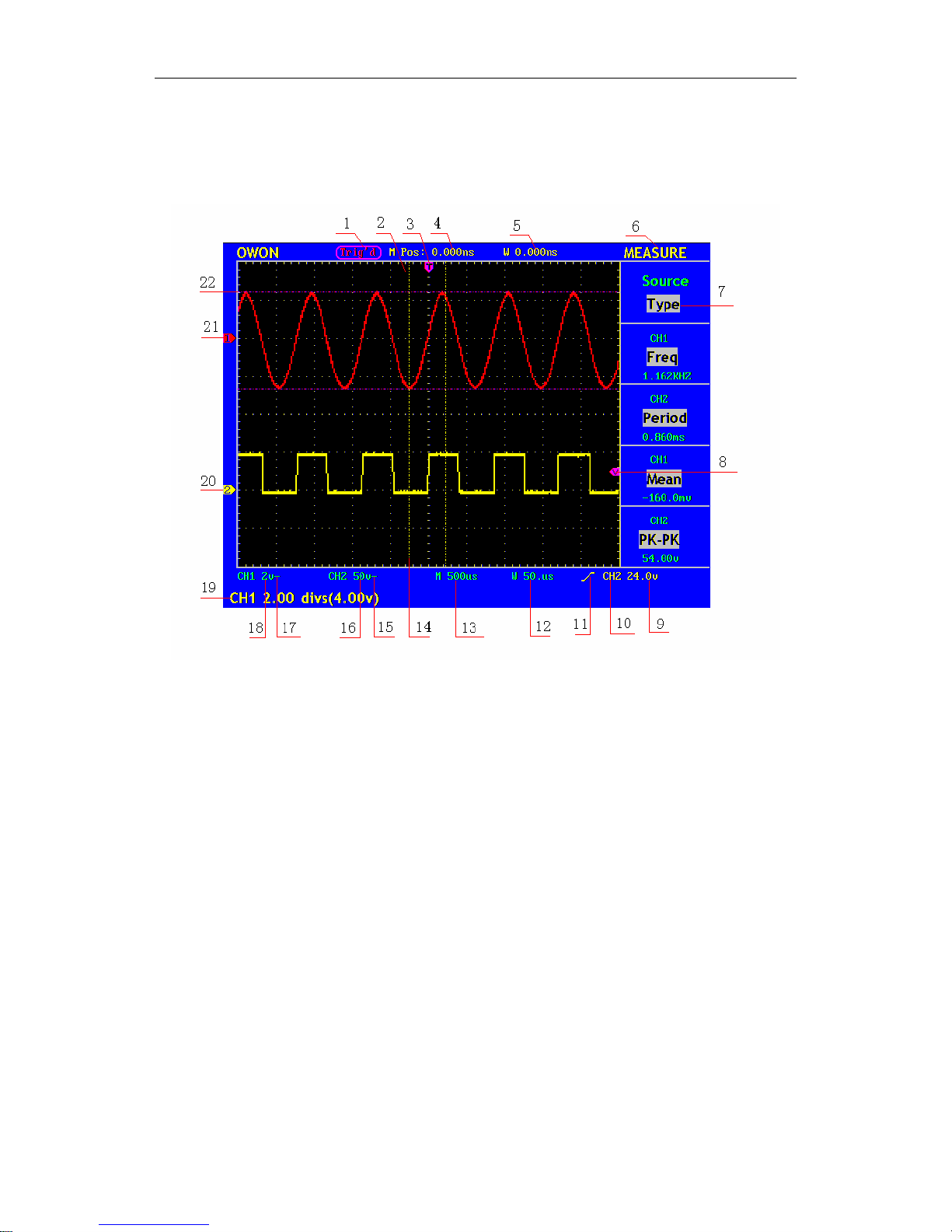
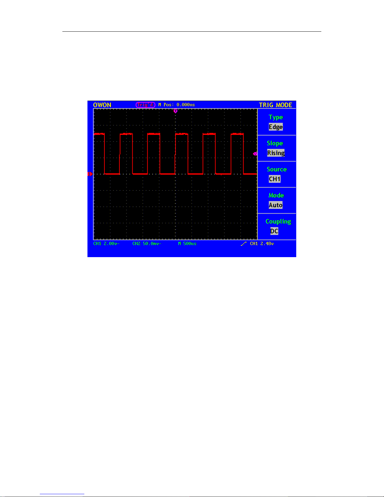
Fig. 3 Illustrative Drawing of Display Interfaces
1. The Trigger State indicates the following information:
Auto: The oscilloscope is under the Automatic mode and is collecting the
waveform under the non-trigger state.
Trig' d: The oscilloscope has already detected a trigger signal and is collecting
the after-triggering information.
Ready: All pre-triggered data have been captured and the oscilloscope has been
already ready for accepting a trigger.
Scan: The oscilloscope captures and displays the waveform data continuously in
the scan mode.
Stop: The oscilloscope has already stopped the waveform data acquisition.
2. Waveform Viewing Area.
3. The purple pointer indicates the horizontal trigger position, which can be adjusted
by the horizontal position control knob.
4. The reading shows the time deviation between the horizontal trigger position and
the screen centre line, which equals 0 in the screen center.
14

User’s Manual of OWON Color Mixed Signal Digital Storage Oscilloscope
5. This reading shows the time deviation between the horizontal trigger position and
the window centre line, which is regarded as 0 in the window center.
6. It indicates the current function menu.
7. It indicates the operation options for the current function menu, which changes
with the function menus.
8. The purple pointer shows the trigger level position.
9. The reading shows the trigger level value.
10. The reading shows the trigger source.
11. It shows the selected trigger type:
Rising edge triggering
Falling edge triggering
Video line synchronous triggering
Video field synchronous triggering
12. The reading shows the window time base set value.
13. The reading shows the main time base set value.
14. The two yellow dotted lines indicate the size of the viewing expanded window.
15. The icon shows the coupling mode of the CH2 channel.
“—” indicates the direct current coupling
“ ~” indicates the AC coupling
16. The reading shows the vertical scale factor (the Voltage Division) of the CH2
channel.
17. The icon indicates the coupling mode of the CH1 channel:
The icon "–" indicates the direct current coupling
The icon "~" indicates the AC coupling
18. The reading indicates the vertical scale factor (the Voltage Division) of the CH1
channel.
19. The information shows the zero point positions of CH1 or CH2 channel.
20. The yellow pointer shows the grounding datum point (zero point position) of the
waveform of the CH2 channel. If the pointer is not displayed, it shows that this
channel is not opened.
21. The red pointer indicates the grounding datum point (zero point position) of the
waveform of the CH1 channel. If the pointer is not displayed, it shows that the
channel is not opened.
15

User’s Manual of OWON Color Mixed Signal Digital Storage Oscilloscope
22. The positions of two purple dotted line cursors measurements.
How to Carry on the General Inspection
After you get a new MSO series oscilloscope, it is recommended that you should
make a check on the instrument according to the following steps:
1. Check whether there is any damage caused by transportation.
If it is found that the packaging carton or the foamed plastic protection cushion has
suffered serious damage, do not throw it away first till the complete device and its
accessories succeed in the electrical and mechanical property tests.
2. Check the Accessories
The supplied accessories have been already described in the Appendix B
“Accessories” of this Manual. You can check whether there is any loss of accessories
with reference to this description. If it is found that there is any accessory lost or
damaged, please get in touch with the distributor of LILLIPUT responsible for this
service or the LILLIPUT’s local offices.
3. Check the Complete Instrument
If it is found that there is damage to the appearance of the instrument, or the
instrument can not work normally, or fails in the performance test, please get in touch
with the LILLIPUT’s distributor responsible for this business or the LILLIPUT’s
local offices. If there is damage to the instrument caused by the transportation, please
keep the package. With the transportation department or the LILLIPUT’s distributor
responsible for this business informed about it, a repairing or replacement of the
instrument will be arranged by the LILLIPUT.
How to Carry on the Function Inspection
Make a fast function check to verify the normal operation of the instrument, according
to the following steps:
1. Connect the Instrument to the Power and Push down the Power Switch Button.
The instrument carries out all self-check items and shows the prompt “Press any Key
Enter system”. Press the “8 (UTILITY)” button to get access to the “FUNCTION”
menu and push down F2 the menu selection button to call out the function “Recall
Factory”. The default attenuation coefficient set value of the probe in the menu is
10X,
2. Set the Switch in the Oscilloscope Probe as 10X and Connect the Oscilloscope
with CH1 Channel.
Align the slot in the probe with the plug in the CH1 connector BNC, and then tighten
the probe with rotating it to the right side.
16
User’s Manual of OWON Color Mixed Signal Digital Storage Oscilloscope
Connect the probe tip and the ground clamp to the connector of the probe
compensator,.
3. Press the “7(AUTOSET)” Button.
The square wave of 1 KHz frequency and 5V peak-peak value will be displayed in
several seconds (see Fig. 4).
Fig. 4 Auto set
Check CH2 by repeating Step 2 and Step 3.
How to Implement the Probe Compensation
When connect the probe with any input channel for the first time, make this
adjustment to match the probe with the input channel. The probe which is not
compensated or presents a compensation deviation will result in the measuring error
or mistake. For adjusting the probe compensation, please carry out the following
steps:
1. Set the attenuation coefficient of the probe in the menu as 10X and that of the
switch in the probe as 10X, and connect the oscilloscope probe with the CH1
channel. If a probe hook tip is used, ensure that it keeps in close touch with the
probe. Connect the probe tip with the signal connector of the probe compensator
and connect the reference wire clamp with the ground wire connector of the
probe connector, and then press the button “7(AUTOSET)”.
2. Check the displayed wave forms and regulate the probe till a correct
compensation is achieved (see Fig. 5 and Fig. 6).
17
User’s Manual of OWON Color Mixed Signal Digital Storage Oscilloscope
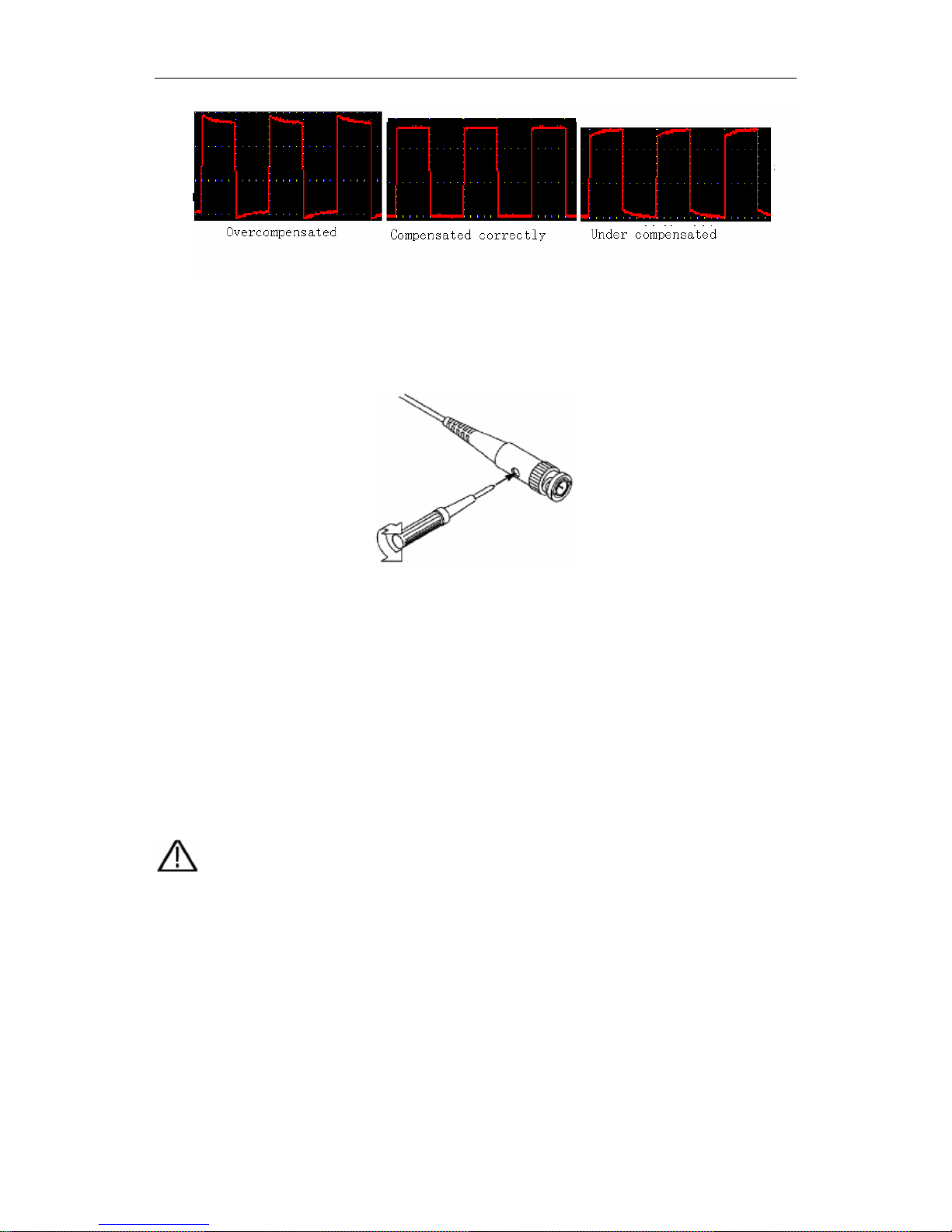
Fig. 5 Displayed Wave Forms of the Probe Compensation
3. Repeat the steps mentioned if necessary.
Fig. 6 Adjust Probe
How to Set the Probe Attenuation Coefficient
The probe has several attenuation coefficients, which will influence the vertical scale
factor of the oscilloscope.
If it is required to change (check) the set value of the probe attenuation coefficient,
press the function menu button of the channels used, then push down the selection
button corresponding to the probe till the correct set value is shown.
This setting will be valid all the time before it is changed again.
Note: The attenuation coefficient of the probe in the menu is preset to 10X when
the oscilloscope is delivered from the factory.
Make sure that the set value of the attenuation switch in the T5100 probe is the same
as the menu selection of the probe in the oscilloscope.
The set values of the probe switch are 1X and 10X (see Fig. 7).
18
User’s Manual of OWON Color Mixed Signal Digital Storage Oscilloscope
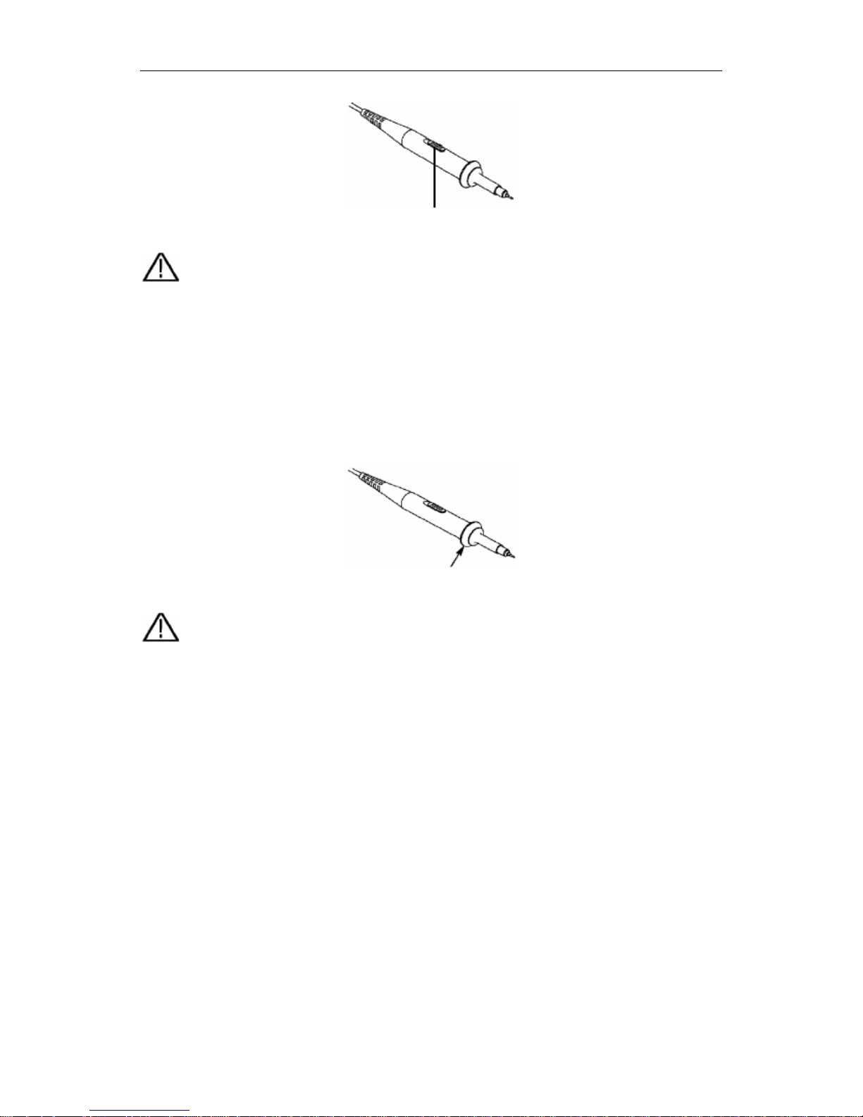
Fig. 7 Attenuation Switch
Note: When the attenuation switch is set to 1X, the T5100 probe will limit the
bandwidth of the oscilloscope in 5MHz. If it is needed to use the whole bandwidth
of the oscilloscope, the switch must be set to 10X.
How to Use the Probe Safely
The safety guard ring around the probe body protects your finger against the electric
shock, shown as Fig. 8.
Fig. 8 Finger Guard
Warning: In order to avoid suffering from the electric shock, please keep your
finger behind the safety guard ring of the probe body during the operation.
In order to protect you from suffering from the electric shock during your using the
probe, do not touch the metal part of the probe tip when the probe is connected to
the power supply.
Before making any measurements, please connect the probe to the instrument and
connect the ground terminal to the earth.
How to Implement Auto-calibration
The auto-calibration application can make the oscilloscope reach the optimum
condition rapidly to obtain the most accurate measurement value. You can carry out
this application program at any time, but when the range of variation of the ambient
temperature is up to or over 5℃, this program must be executed.
For the performing of the self-calibration, all probes or wires should be disconnected
with the input connector first. Then, press the “8(UTILITY)” button to call out the
FUNCTION menu; push down the F3 menu selection button to choose the option
19
User’s Manual of OWON Color Mixed Signal Digital Storage Oscilloscope
“ Do Self Cal”; finally, run the program after confirming that everything is ready now.
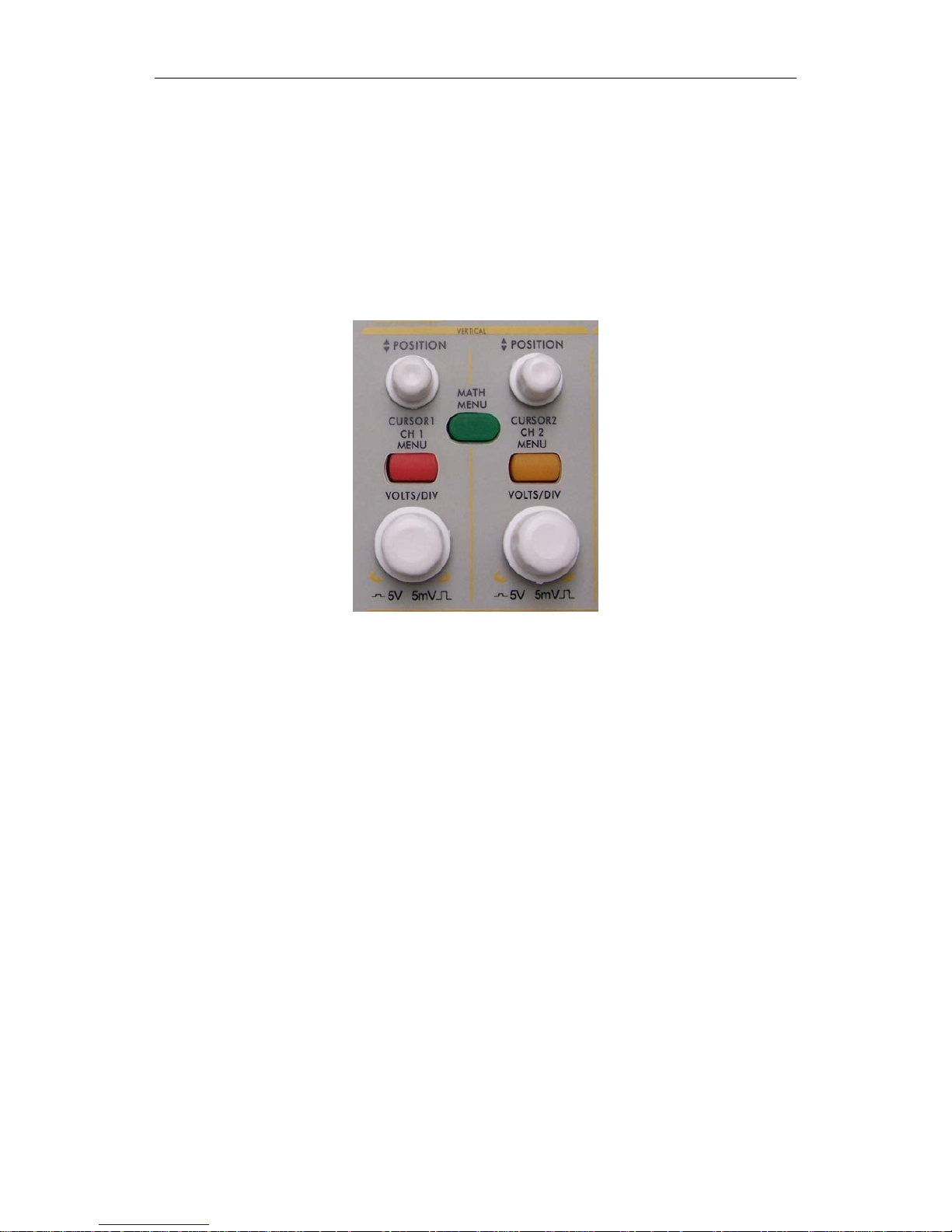
Introduction to the Vertical System
Shown as Fig.9, there are a series of buttons and knobs in VERTICAL CONTROLS.
The following practices will gradually direct you to be familiar with the using of the
vertical setting.
Fig. 9 Vertical Control Zone
1. Use the button “VERTICAL POSITION” knob to show the signal in the center
of the waveform window. The “VERTICAL POSITION” knob functions the
regulating of the vertical display position of the signal. Thus, when the
“VERTICAL POSITION” knob is rotated, the pointer of the earth datum point
of the channel is directed to move up and down following the wave form.
Measuring Skill
If the channel is under the DC coupling mode, you can rapidly measure the DC
component of the signal through the observation of the difference between the wave
form and the signal ground.
If the channel is under the AC mode, the DC component will be removed by filtration.
This mode helps you display the AC component of the signal with a higher
sensitivity.
2. Change the Vertical Setting and Observe the Consequent State Information
Change.
With the information displayed in the status bar at the bottom of the waveform
window, you can determine any changes in the channel vertical scale factor.
z Rotate the vertical “VOLTS/DIV” knob and change the “Vertical Scale Factor
(Voltage Division)”, it can be found that the scale factor of the channel
20
User’s Manual of OWON Color Mixed Signal Digital Storage Oscilloscope
corresponding to the status bar has been changed accordingly.
z Press buttons of “CH1 MENU”, “CH2 MENU” and “MATH MENU”, the
operation menu, symbols, wave forms and scale factor status information of the
corresponding channel will be displayed in the screen.
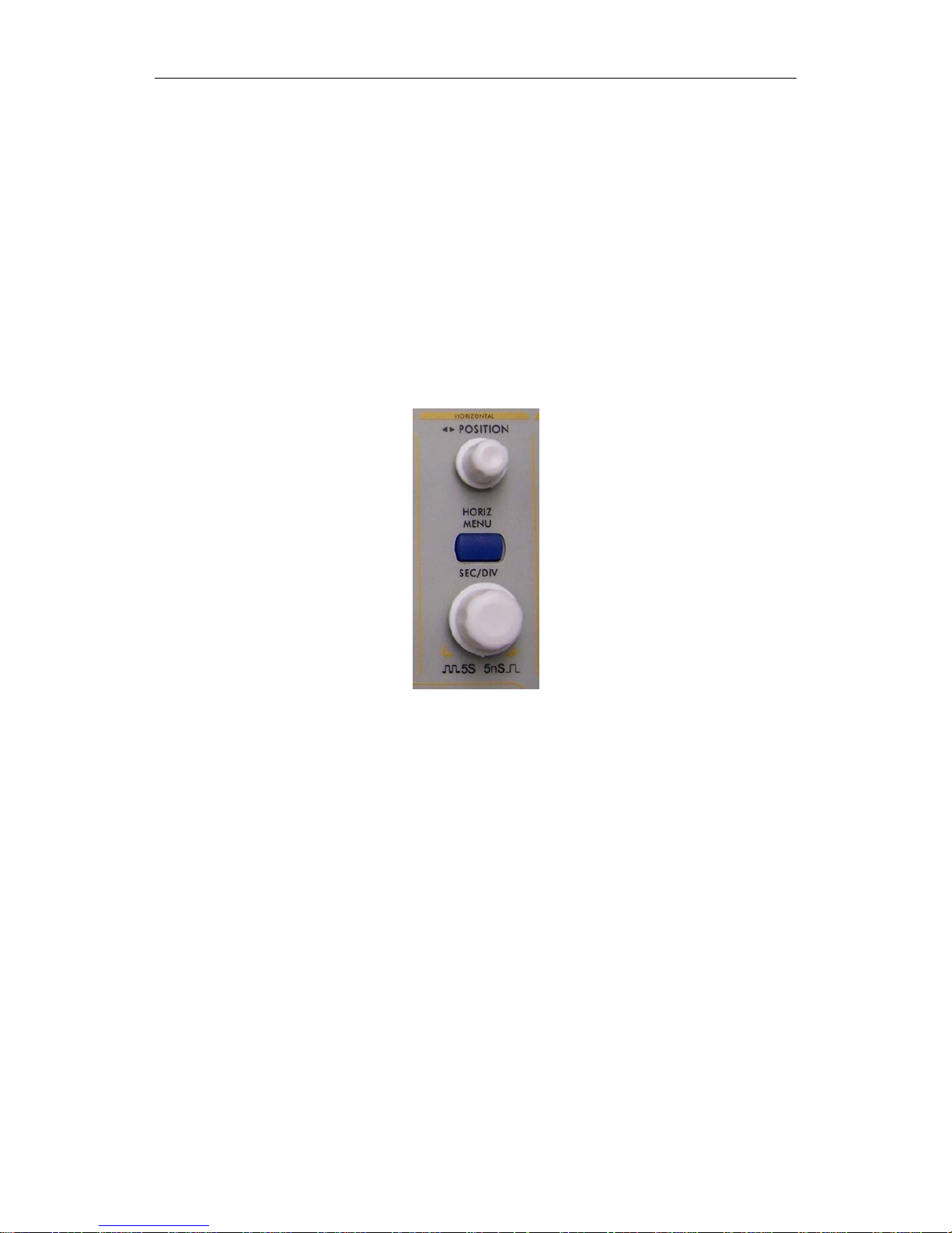
Introduction to the Horizontal System
Shown as Fig.10, there are a button and two knobs in the “HORIZONTAL
CONTROLS”. The following practices will gradually direct you to be familiar with
the setting of horizontal time base.
Fig. 10 Horizontal Control Zone
1. Use the horizontal “SEC/DIV” knob to change the horizontal time base setting
and observe the consequent status information change. Rotate the horizontal
“SEC/DIV” knob to change the horizontal time base, and it can be found that the
“Horizontal Time Base” display in the status bar changes accordingly. The
horizontal scanning speed steps from 5ns up to 5s in the sequence of 1=2=5.
2. Use the “HORIZONTAL POSITION” knob to adjust the horizontal position of
the signal in the waveform window. The “HORIZONTAL POSITION” knob is
used to control the triggering displacement of the signal or for other special
applications. If it is applied to triggering the displacement, it can be observed that
the wave form moves horizontally with the knob when you rotate the
“Horizontal Position” knob.
3. With the “HORIZONTAL MENU” button pushed down, you can set and
initiate the Window Expansion.
21
User’s Manual of OWON Color Mixed Signal Digital Storage Oscilloscope
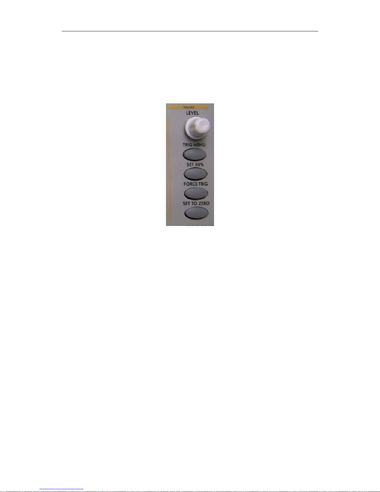
Introduction to the Trigger System
Shown as Fig.11, there are a knob and four buttons in the “TRIGGER
CONTROLS”. The following practices will direct you to be familiar with the setting
of the trigger system gradually.
Fig. 11 Trigger Control Zone
1. Press the “TRIG MENU” button and call out the trigger menu. With the
operations of the 5 menu selection buttons, the trigger setting can be changed.
2. Use the “LEVEL” knob to change the trigger level setting.
With the rotation of the “LEVEL” knob, it can found that the trigger indicator in
the screen will move up and down with the rotation of the knob. With the
movement of the trigger indicator, it can be observed that the trigger level value
displayed in the screen changes.
3. Press the button “SET TO 50%” to set the trigger level as the vertical mid point
values of the amplitude of the trigger signal.
4. Press the “FORCE TRIG” button to force a trigger signal, which is mainly
applied to the “Normal" and "Single” trigger modes.
5. The “SET TO ZERO” button is used to reset the trigger horizontal position.
22
User’s Manual of OWON Color Mixed Signal Digital Storage Oscilloscope
Logic Analyzer
LA input connection
Insert the plug of OL-16 LA module 50P into the LA signal input on front
panel and fix two screw. Then 16 channel clamp of OL-16 LA connect to target
singal and ready for measurement
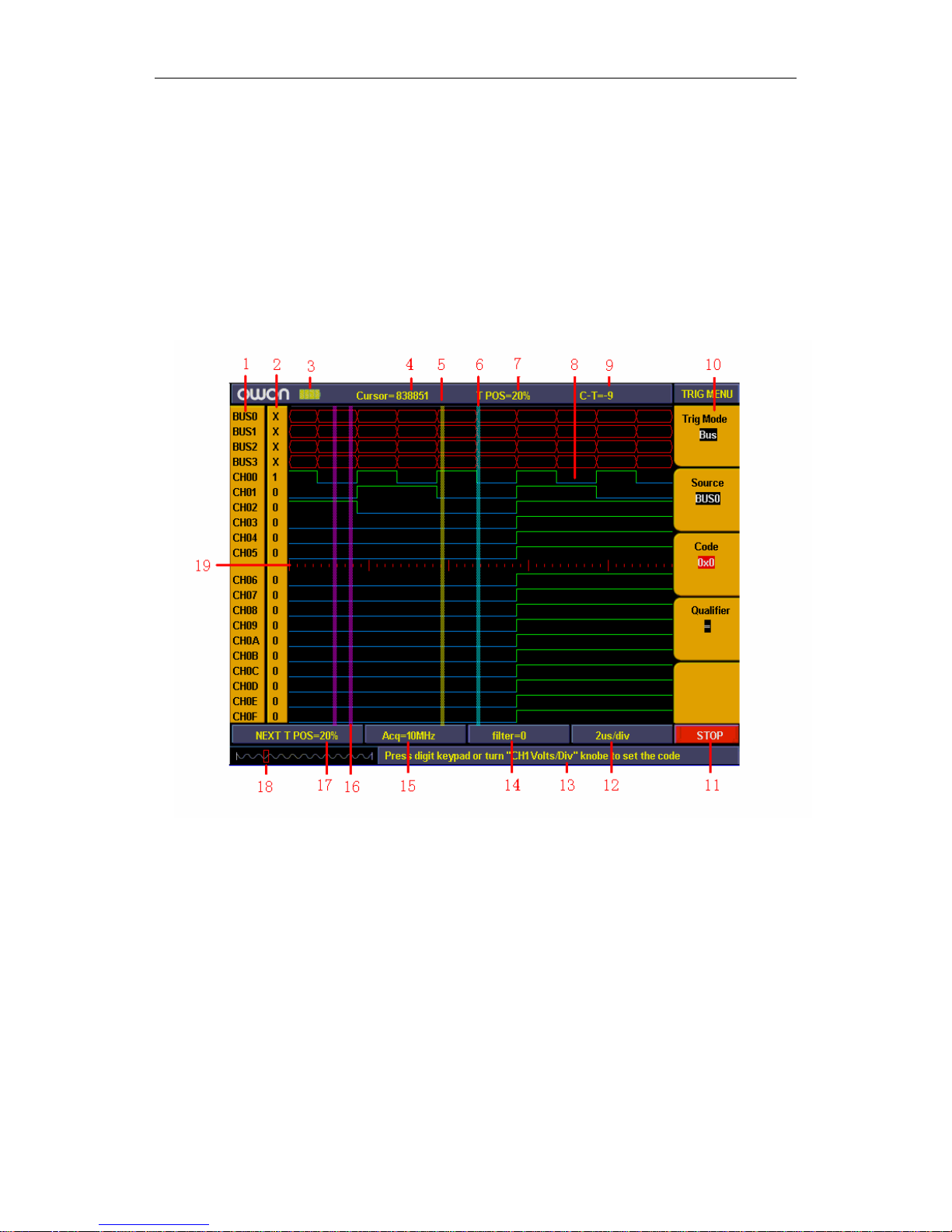
User interface introduction
Fig12:User interface of logic analyzer
1、Channel and Bus indicate: display current working channel and bus 。
2、Channel binary value display: display binary system value for the channel position in
current cursor 。
3、Battery powers indicate: indicate battery power when battery inside。
4、Decimal system value indicate the position of current cursor in storage area。
5、Yellow dashed line indicates current cursor。
6、Blue dashed line indicates current trigger position。
7、Percentage value indicate current trigger position in storage area。
8、Sample data area indication: red for bus, blue and green for “0”, “1” in each channel
data。
9、Decimal system value indicate the position of current cursor relate to current trigger。
10、Operation options indicate current function menu and different function menu have
23

User’s Manual of OWON Color Mixed Signal Digital Storage Oscilloscope
different display。
11、Sample status indicate: “RUN” for sampling and wait for trigger, “TRIG” for trigger
detected and wait for sample finished. “STOP” for sampling finished。
12、Value indicate current time base。
13、Info windows: different operation display different info。
14、Value display current filter modulus setting。
15、Value display current sample rate setting。
16、Two purple lines for cursor 1 and cursor 2 in cursor measurement
17、Percentage value indicate trigger position for next sampling in storage area。
18、Red square indicate the current sampling data position in storage area。
19、Red scale line indicates the time base width in sampling data display area and totally
4.8 divisions. The width between two long scale lines is 1 division and between short
scale lines are 0.1 divisions。
How to acquire data
When you start to acquire LA begins sampling data from the probes. Then each time
clock occurs the data will be sampled.
Then sampled data is sent to trigger function block and store in main memory. The
trigger program checks specific events with the sampled data and take specific action. The
trigger program can check events as rising edge, data values, and data ranges etc. LA
module enables a post trigger delay counter when trigger reach specified value and to
allow post trigger portion of the acquisition memory to fill before data acquisition stops.
Press “F” to get into data acquisition mode after finish setting for trigger and
sampling. Then running status display as “RUN” and running status display “TRIG”
when detected trigger signal and display “STOP” when data acquisition finished. Then
you can start to analyze data. Data acquisition can be stopped by press “F” again during
the process.
Note:
When running status display as “RUN”、“TRIG” during data acquiring
process ,only "F" key for operate and other keys or knobs are idle. Only
till status display as "STOP" then others operation are working.
How to observe and analyze the data
Follow up below steps to observe and analyze the current data acquired:
1、Turn “Sec/Div” knob to adjust the time length for data display in each division (to
adjust the data resolution displayed).
2、Turn “Cursor” knob to observe more details for the data of current cursor position.
The data of binary value for current cursor position display in binary system
area and power on measure menu then bus value for current cursor position will
display in measurement window.
3、Turn “horizontal position” knob can move the current displayed data to left/right
position in storage area quickly.
24
User’s Manual of OWON Color Mixed Signal Digital Storage Oscilloscope
We will use a simple measurement example to explain the primary setting for LA
measurement.
We need to measure a three lines SPI signal, three signal are enable, clock and data.
Clock is in effect when enable is low clock data, and clock frequency is 1M, data width is
32 digits, every clock corresponds to one data. Signal voltage is 3.3V.
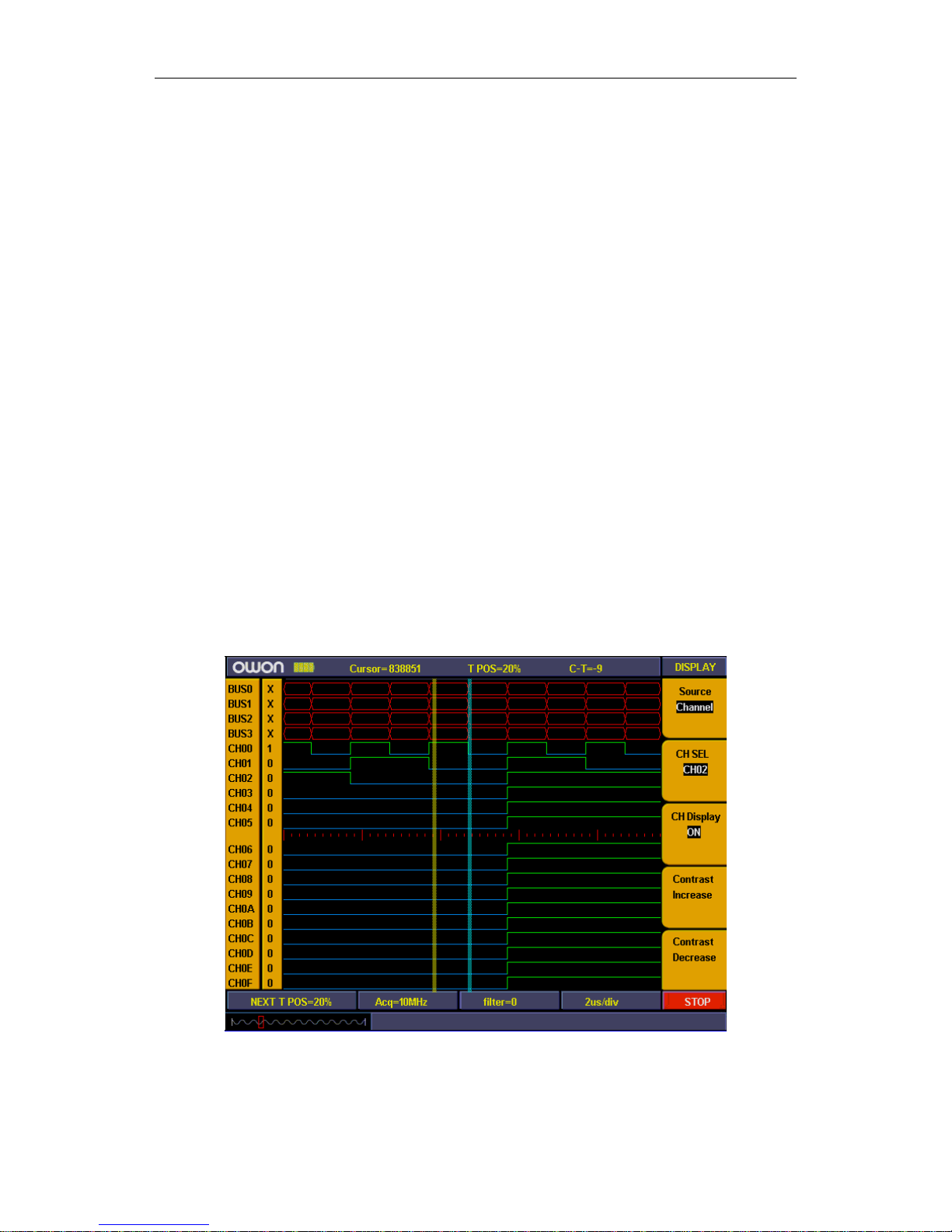
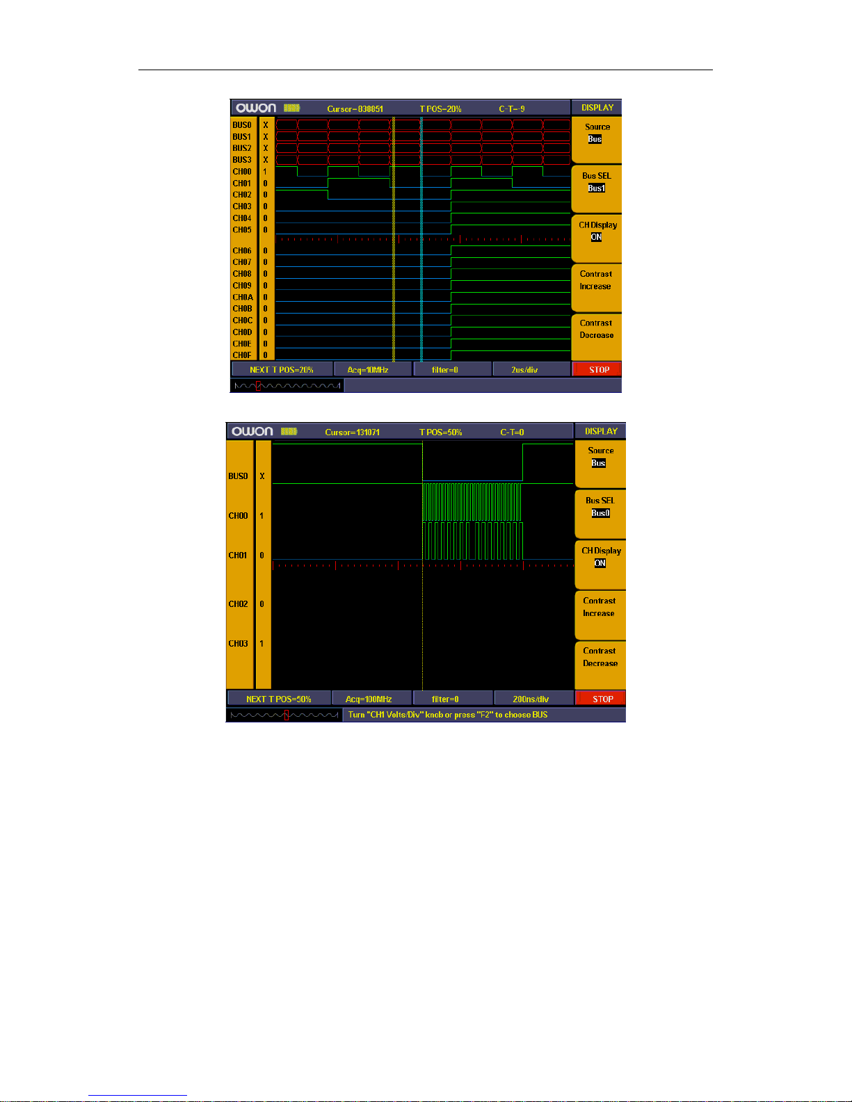
Display systems
We need only three channels as what we measure is 3 signals. And other channel and
bus can be off. In this way the display resolution in using channel will be increased.
Display system mainly to set on/off for measure channel. We use CH00、CH01、
CH02 as measure channel correspond to signal enable, clock, data accordingly. Other
channel and bus is off.
1、Press “A(DISPLAY)” and display menu appears.
2. Press “F1” till signal sources display as“Channel”
3. Press “F2” or turn “CH1 Volts/Div” knob till channel No. display as “CH00”.
4. Press “F3” and set the signal sources as “ON”. Repeat operation of steps 3.4 and
set CH01, CH02 as “ON” and CH03-CHOF as “OFF”. Refer to fig. 13
5. Press “F1” till sources display as“ BUS”.
6. Press “F2” till Bus No. display as“BUS0”
7. Press “F3” and set signal sources as “OFF”. Repeat operation of steps 6.7 and
set BUS1、BUS2、BUS3 all as “OFF”. Ref to fig. 14
Now display panel only show CH00、CH01、CH02 and others channel and bus are all off.
Ref to fig. 15
Figure 13
25
User’s Manual of OWON Color Mixed Signal Digital Storage Oscilloscope
Figure 14
Figure 15
Trigger system
LA is same as DSO and need to make trigger to synchronize data. The trigger system
mainly to set trigger sources, trigger mode and trigger position.
We make CH00 as trigger source and trigger mode as falling edge, trigger position in
50%. Trigger system setting steps as below
1. Press “Trig menu” and menu appears.
2. Press “F1” till trigger mode display as “Edge”.
3. Press “F2” or turn “CH1 Volts/Div” till trigger sources display as “CH00”.
4. Press “F3” till trigger type display as “Falling”.
5. Turn “Trigger adjust” knob or press “SET 50%”till “NEXT T POS” window
display as “50%”
26
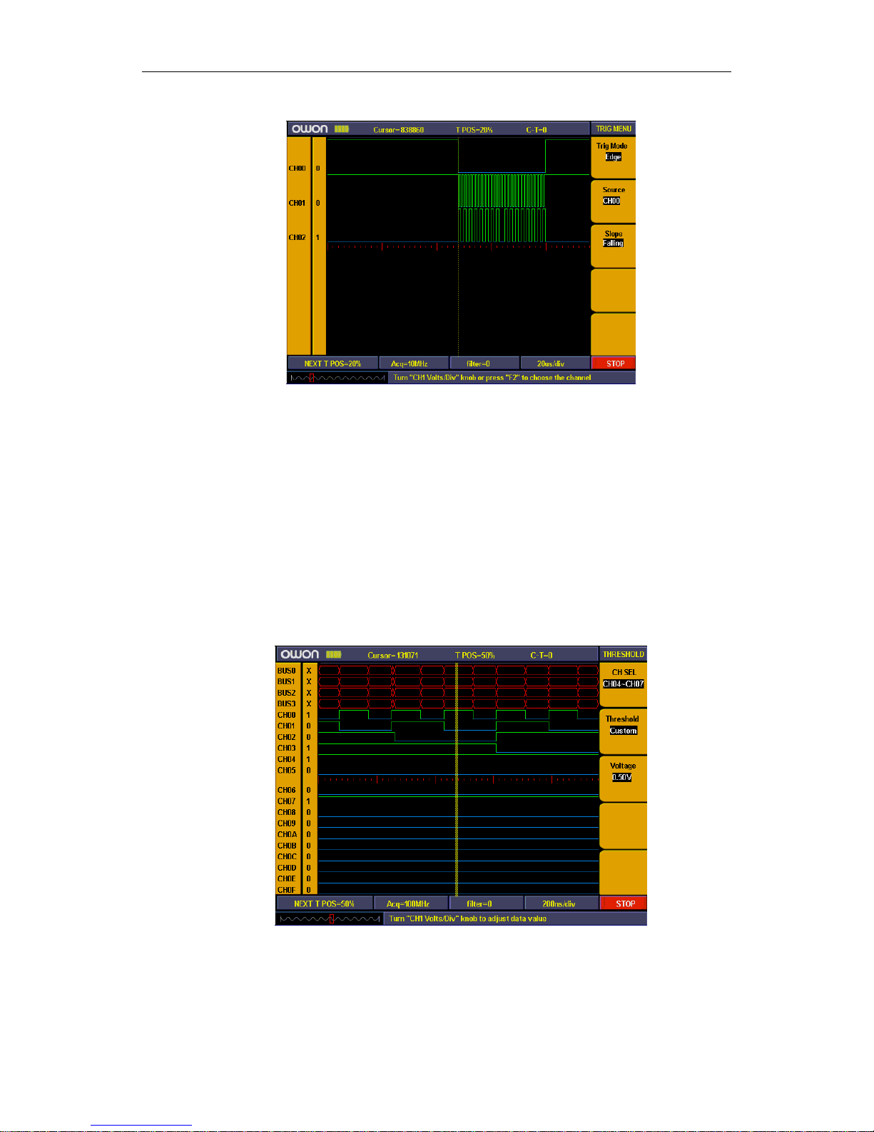
User’s Manual of OWON Color Mixed Signal Digital Storage Oscilloscope
Then trigger system setting finished (ref to fig. 16).
Figure 16
Threshold voltage system
Threshold voltage system is to set high/low of the trigger voltage. The system already
fixed the setting for normal logic voltage as CMOS, LVMOS etc. And you can set any
trigger voltage using custom setting.
The signal voltage is 3.3V and we set threshold voltage as “LVCMO3.3/1.7V” as
below steps:
1. Press “1 (Threshold)” key and the menu appears.
2. Press “F1” key till Channel display as “CH00~CH03”
3. Press “F2” key till threshold display as “LVCMOS3.3/1.7V”.
Then the threshold setting is finished (ref to fig. 17).
Figure 17
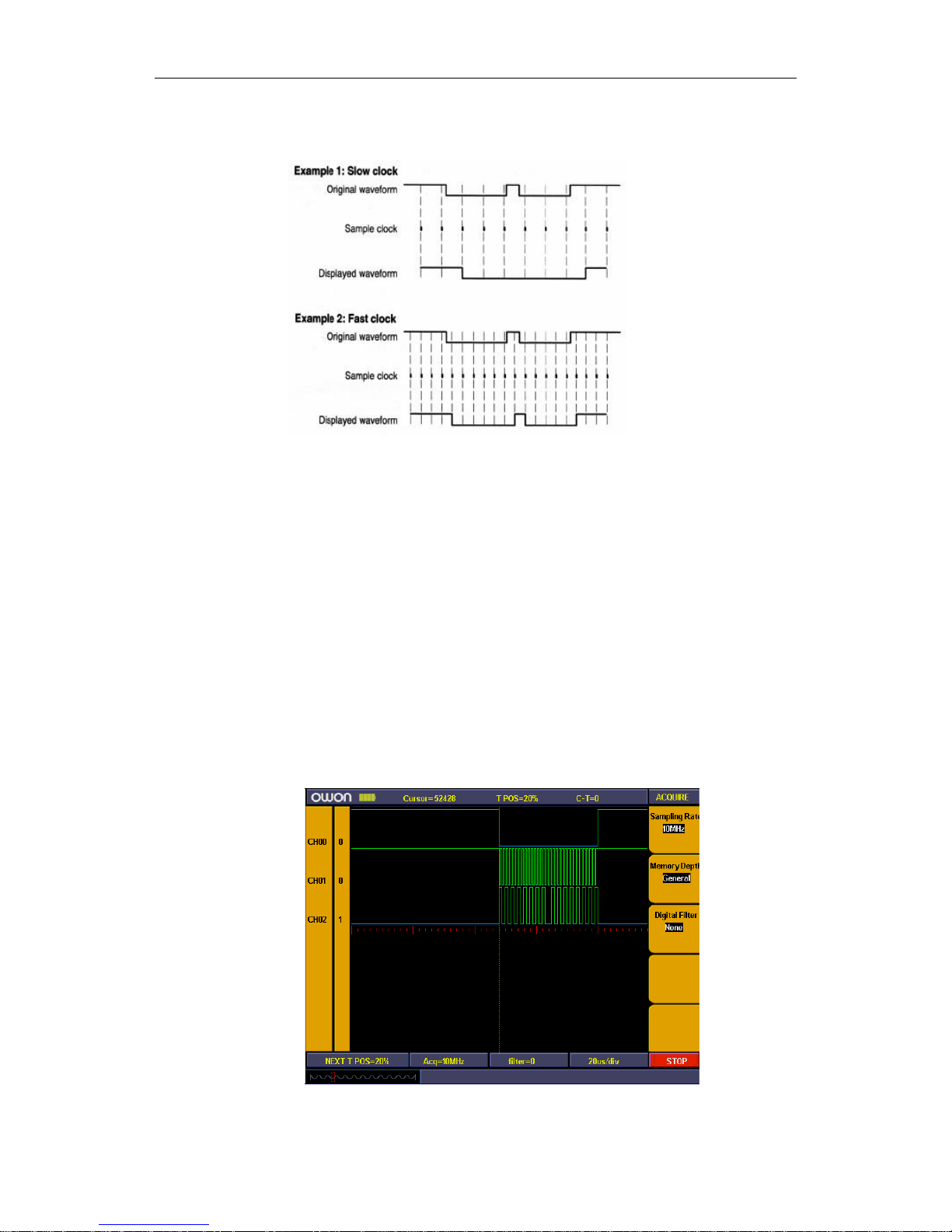
Sampling system
The waveform accuracy reverts from sample data depend on sample rate for
measured signals. The waveform reverted in LA is referring to the sample signals storage
27
User’s Manual of OWON Color Mixed Signal Digital Storage Oscilloscope
in the memory. The recorded data will display in error if the sample rate is too lower.
Below figures explains how sample rate influence the waveform recorded in LA.
Figure 18
There is an importance compromise between recorded signal resolution and its
continuance (relate to time). The sample memory depth of LA is fixed and once adding
sample rate then resolution will get better accordingly. But it will decrease the
continuance for acquire signal. In a word, sample rate are quicker then the continuance for
recorded signal will get smaller but with better resolution.
Sampling system can set difference sample rate and storage depth.
We use 10 times sampling rate to measure the signal clock frequency of 1M. and
storage depth set as “Normal”. Sampling system setting steps as below:
1. Press “E(ACQUIRE)” and menu appears.
2. Press “F1” or turn “CH1 Volts/div” knob till sample rate setting display as“10M”.
3. Press “F2” till storage depth display as “General”.
Sampling system setting finished (ref to the fig.)
Then press “F” and start to sampling data. Display show as fig. 19 when sampling
finished.
Figure 19
28

User’s Manual of OWON Color Mixed Signal Digital Storage Oscilloscope
Advanced User Guidebook
Up till now, you have already been familiar with the initial operations of the
functions of the function areas, buttons and knobs in the front panel of the MSO series
oscilloscope. Based the introduction of the previous Chapter, the user should have an
intimate knowledge of the determination of the change of the oscilloscope setting through
observing the status bar. If you have not been familiar with the above-mentioned
operations and methods yet, we advise you to read the section of “Chapter One Junior
Users' Guidebook”.
This chapter will deal with the following topics mainly:
Digital Storage Oscilloscope
z How to Set the Vertical System
z How to Set the Horizontal System
z How to Set the Trigger System
z How to Carry on the Sampling Setup
z How to Set the Display System
z How to Implement the Storage and Call-out Operations
z How to Carry on the Auxiliary Function Setting
z How to Carry on the Automatic Measurement
z How to Carry on the Cursor Measurement
z How to Use Executive Buttons
Logic analyzer
z How to set sampling system
z How to set trigger system
z How to set threshold
z How to set display system
z How to set BUS
z How to measure
z How to save and loading
z How to use USB Mass storage device to storage
z How to search
z How to review setting info
z How to use cursor measurement
z How to set help
29
User’s Manual of OWON Color Mixed Signal Digital Storage Oscilloscope
It is recommended that you read this chapter carefully to get acquainted the various
measurement functions and other operation methods of the MSO series oscilloscope.
Digital Storage Oscilloscope
How to Set the Vertical System
The VERTICAL CONTROLS includes three menu buttons such as CH1 MENU,
CH2 MENU and MATH MENU, and four knobs such as VERTICA POSITION,
VOLTS/DIV (one group for each of the two channels).
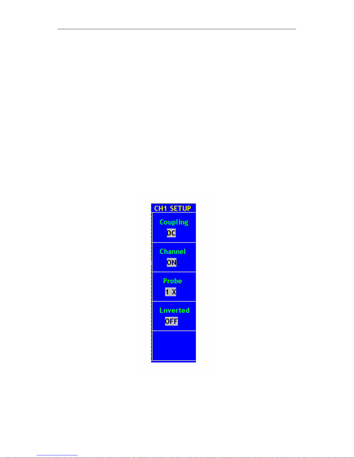
Setting of CH1 and CH2
Every channel has an independent vertical menu and each item is set respectively
based on the channel.
With the “CH1 MENU” or “CH2 MENU” menu button pushed down, the system
shows the operation menu of the corresponding channel (see Fig. 20).
Fig. 20 Channel Setting Menu
30
 Loading...