

Owon B35 User Manual

General Warranty
OWON warrants that the product will be free from defects in materials and workmanship
for a period of 1 year from the date of purchase of the product by the original purchaser
from the OWON Company. This warranty only applies to the original purchaser and is not
transferable to the third party, and does not apply to fuses, disposable batteries or to any
product which has been misused, altered, neglected or damaged by accident or
abnormal conditions of operation or handling.
If the product proves defective during the warranty period, OWON either will repair the
defective product without charge for parts and labor, or will provide a replacement in
exchange for the defective product. Parts, modules and replacement products used by
OWON for warranty work may be new or reconditioned like new performance. All
replaced parts, modules and products become the property of OWON.
In order to obtain service under this warranty, customer must notify OWON of the defect
before the expiration of the warranty period. Customer shall be responsible for
packaging and shipping the defective product to the service center designated by OWON,
and with a copy of customer proof of purchase.
This warranty shall not apply to any defect, failure or damage caused by improper use or
improper or inadequate maintenance and care. OWON shall not be obligated to furnish
service under this warranty a) to repair damage resulting from attempts by personnel
other than OWON representatives to install, repair or service the product; b) to repair
damage resulting from improper use or connection to incompatible equipment; c) to
repair any damage or malfunction caused by the use of non-OWON supplies; or d) to
service a product that has been modified or integrated with other products when the
effect of such modification or integration increases the time or difficulty of servicing the
product.
Please contact the nearest OWON's Sales and Service Offices for services or a complete
copy of the warranty statement.
For better after-sales service, please visit www.owon.com.cn and register the purchased
product online.
Excepting the after-sales services provided in this summary or the applicable warranty statements,
OWON will not offer any guarantee for maintenance definitely declared or hinted, including but not
limited to the implied guarantee for marketability and special-purpose acceptability. OWON should
not take any responsibilities for any indirect, special or consequent damages.
For more details, please refer to the user manual, it can be downloaded at
www.owon.com.cn .

1.Safety Information
1
1. Safety Information
Safety Considerations
Before any operations, please read the following safety precautions to
avoid any possible bodily injury and prevent damage to this product or any
other products connected. To avoid any contingent danger, use this
product only as specified.
Limit operation to the specified measurement category, voltage, or
amperage ratings.
Do not use the multimeter if it is damaged. Before you use the
multimeter, inspect the case. Look for cracks or missing plastic. Pay
particular attention to the insulation surrounding the connectors.
Do not use the test leads provided for other products. Use only the
certified test leads specified for this product.
Inspect the test leads for damaged insulation or exposed metal.
Before use, verify the multimeter's operation by measuring a known
voltage.
Only the qualified technicians can implement the maintenance.
Always use the specified battery type. The power for the multimeter is
supplied with two standard AA 1.5 V batteries. Observe the correct
polarity markings before you insert the batteries to ensure proper
insertion of the batteries in the multimeter.
Check all Terminal Ratings. To avoid fire or shock hazard, check all
ratings and markers of this product. Refer to the user's manual for more
information about ratings before connecting to the multimeter.
Do not operate the multimeter with the cover or portions of the cover
removed or loosened.
Use Proper Fuse. Use only the specified type and rating fuse for the
multimeter.
Do not operate if in any doubt. If you suspect damage occurs to the
multimeter, have it inspected by qualified service personnel before
further operations.
To avoid electric shock, do not operate this product in wet or damp
conditions.
Do not operate in an explosive atmosphere.
Keep product surfaces clean and dry.
Do not apply more than the rated voltage (as marked on the multimeter)
between terminals, or between terminal and earth ground.

1.Safety Information
2
When measuring current, turn off the circuit power before connecting
the multimeter in the circuit. Remember to place the multimeter in
series with the circuit.
When servicing the multimeter, use only the specified replacement
parts.
Use caution when working above 60 V DC, 30 V AC RMS, or 42.4 V peak.
Such voltages pose a shock hazard.
When using the test leads, keep your fingers behind the finger guards on
the test leads.
Remove the test leads from the multimeter before you open the battery
co ve r.
To avoid false readings, which may lead to possible electric shock or
personal injury, replace the battery as soon as the low battery indicator
appears and flashes.
Disconnect circuit power and discharge all high-voltage capacitors before
testing resistance, continuity, diodes, or capacitance.
Use the proper terminals, function, and range for your measurements.
When the range of the value to be measured is unknown, set the rotary
switch position as the highest range, choose the auto ranging mode. To
avoid damages to the multimeter, do not exceed the maximum limits of
the input values shown in the technical specification tables.
Connect the common test lead before you connect the live test lead.
When you disconnect the leads, disconnect the live test lead first.
Before changing functions, disconnect the test leads from the circuit
under test.
1.Safety Information
3
Measurement Category
The multimeter has a safety rating of 1000 V, CAT III.
Safety Terms and Symbols
Safety Terms
Terms in this Manual. The following terms may appear in this manual:
Warning: Warning indicates the conditions or practices that could result in
personal injury or death.
Caution: Caution indicates the conditions or practices that could result in
damage to this product or other property.
Terms on the Product. The following terms may appear on this product:
Danger: It indicates an injury or hazard may immediately happen.
Warning: It indicates an injury or hazard may be accessible potentially.
Caution: It indicates a potential damage to the instrument or other property might occur.
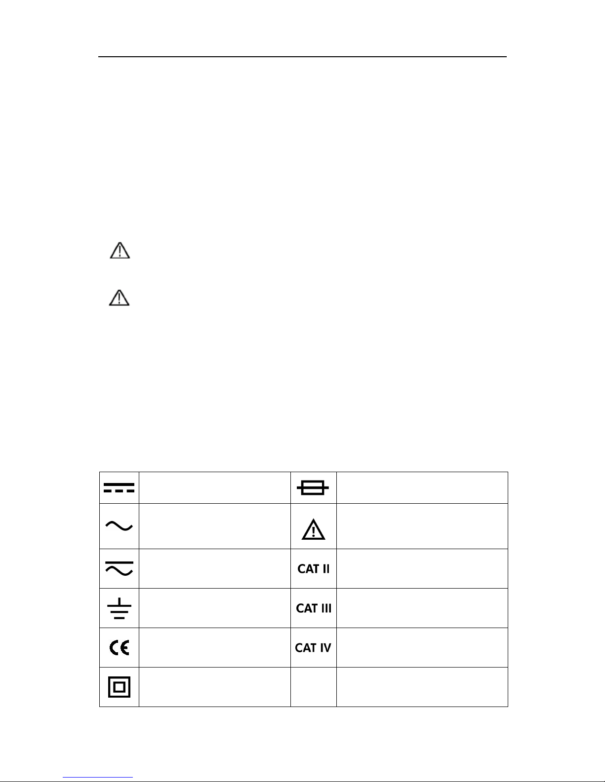
Safety Symbols
Symbols on the Product. The following symbol may appear on the product:
Direct current (DC)
Fuse
Alternating current (AC)
Caution, risk of danger (refer to this
manual for specific Warning or
Caution information)
Both direct and alternating
current
Category II overvoltage protection
Ground terminal
Category III overvoltage protection
Conforms to European Union
directives
Category IV overvoltage protection
Equipment protected throughout
by double insulation or
reinforced insulation
2.Multimeter in Brief
4
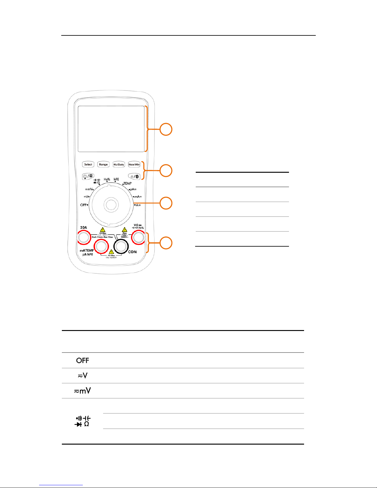
2. Multimeter in Brief
Front panel
1
2
3
4
No.
Description
①
Display screen
②
Keypad
③
Rotary switch
④
Input terminals
Figure 2-1 Front panel overview (B35 shown)
Rotary switch
Position
Description
Power off
DC or AC voltage measurement
DC or AC voltage measurement (up to 600 millivolts)
Continuity test
Capacitance measurement
Diode test
2.Multimeter in Brief
5
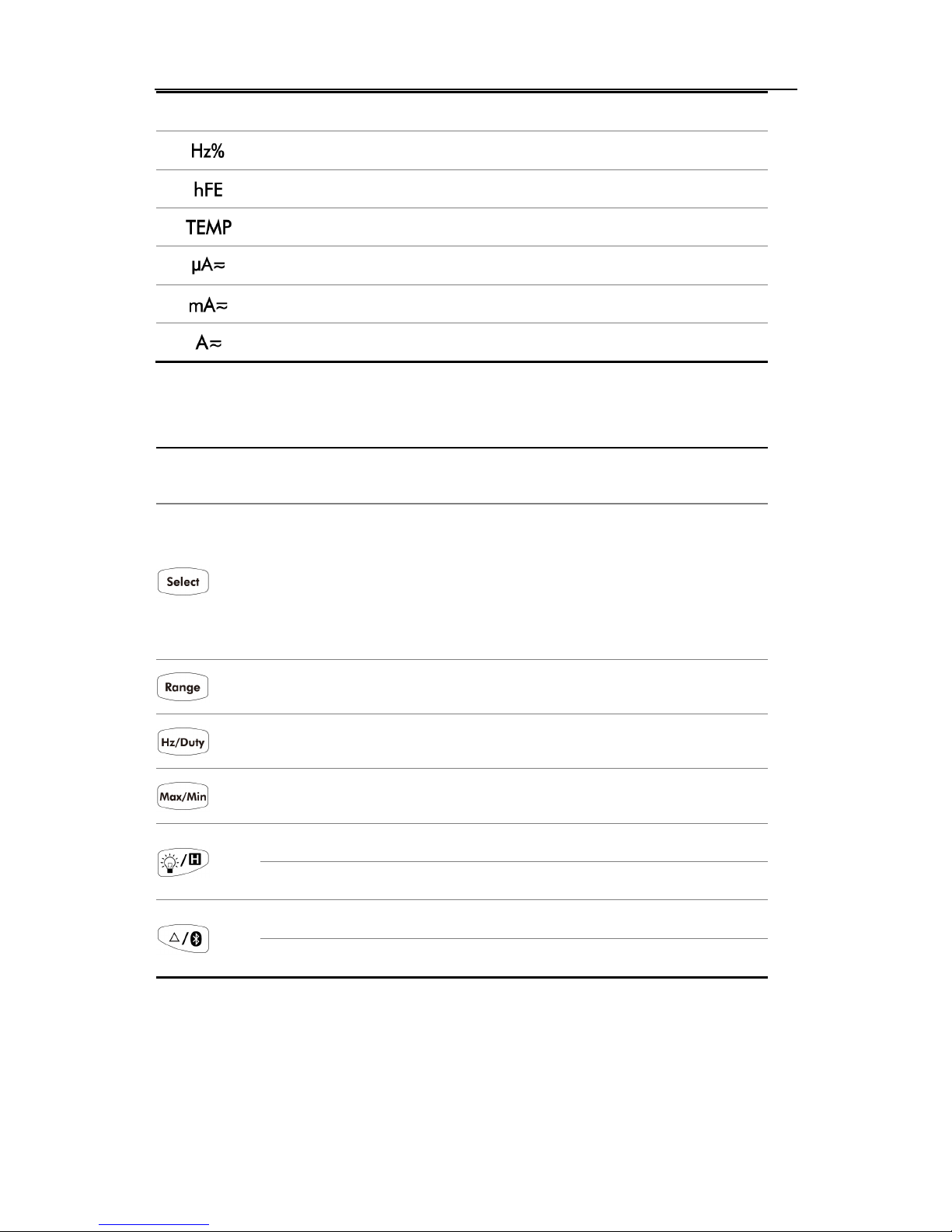
Resistance measurement
Frequency measurement
Transistor measurement
— Not available on B41T(+)
Temperature measurement
DC or AC current measurement (up to 600 microamperes)
DC or AC current measurement (up to 600 milliamperes)
DC or AC current measurement
Keypad
Key
Description
Select function:
Select DC or AC
Select ℃ or ℉ during temperature measurements
Select Resistance/Diode/Continuity/Capacitance
Note: Select Resistance/Diode/Continuity on B41T(+).
Auto/Manual range
Select frequency/duty cycle
Capturing Max. and Min. Values
Backlight
Data Hold
Relative Measurements
Bluetooth (only for the model with Bluetooth)
2.Multimeter in Brief
6
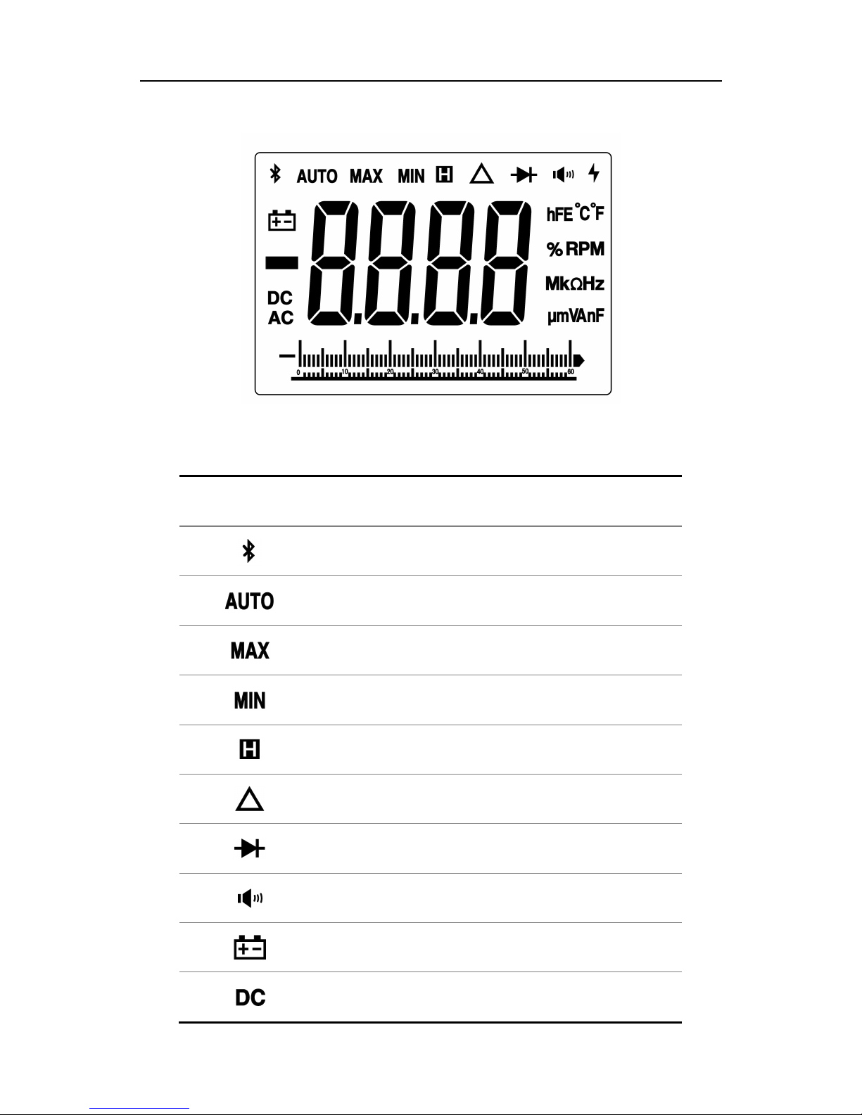
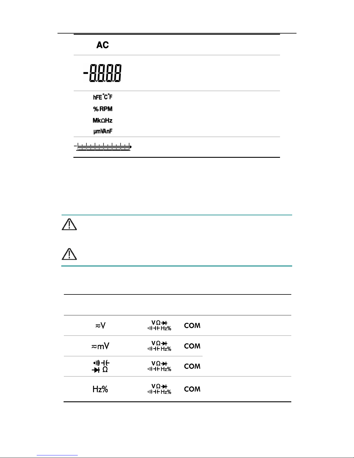
Display screen
Figure 2-2 Display screen
Symbol Description
Bluetooth enabled
Auto range
Maximum reading
Minimum reading
Data hold enabled
Relative enabled
Diode test selected
Continuity test selected
Battery is low
DC
2.Multimeter in Brief
7
AC
Measurement display
("OL" is short for overload, indicates the
reading exceeds the display range)
Measuring units
Analog bar graph
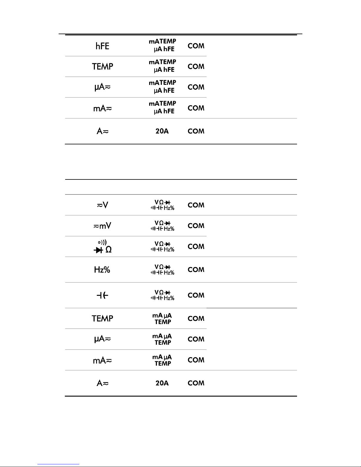
Input terminals
The terminal connections for the different measurement functions of the
multimeter are described in the table below.
Warning: Before starting any measurement, observe the rotary
switch position of the multimeter, and then
connect the
test leads to the correct terminals.
Caution:
To avoid damaging the multimeter
, do not exceed the rated
input limit.
Input terminals on 35 series multimeter
Rotary switch position
Input terminals Overload protection
750 VAC/1000 VDC
250 VDC or
Equivalent voltage RMS
250 VAC or
Equivalent voltage RMS
2.Multimeter in Brief
8
1A/250V, fast-acting
fuse
20A/250V, fast-acting
fuse
Input terminals on B41T(+)
Rotary switch position
Input terminals
Overload protection
750 VAC/1000 VDC
250 VDC or
Equivalent voltage RMS
250 VAC or
Equivalent voltage RMS
250 VDC or
Equivalent voltage RMS
1A/250V, fast-acting
fuse
20A/250V, fast-acting
fuse
 Loading...