

OWLink FO2800, FO2850 Quick Start Manual

TX (Transmitter) Installation
OWLink FO TX2800
Power
IR
OUT
DLI HDMI
IN
OWLink FO TX2850
Power
IR
OUT
DLI HDMI
IN
Audio
IN
USBto PC
STEP 1: Connect Video Source to FO 2800 TX/ FO 2850 TX
DVD playervideo source
Connect HDMIto DVD
Connect HDMIto FO 2800 or FO 2850 TX
Connect DVIto PC Connect PCto FO 2800 or FO 2850 TX using DVI to
HDMI cable
1-A: Connect DVD, STB, Video Game Box to TX
1-B: Connect PC to TX
Connect IRemitter to
FO 2800TX / FO 2850 TX
LocateIR sensor on DVD
or othersource device
(* Youmay use the remote
control tolocate the IR
sensor )
Stick IRemitter on DVD
or othersource device
sensor
STEP 2: Connect IR emitter to source device
(Option: for FO 2850 only)
STEP 3: Connect Stereo Audio source to FO 2850 TX
DVD playerStereo Audio source
Connect stereoaudio cable
to DVDor other audio source
Stereo (red/ white)to mini
jack cable
(not provided)
Connect audiosource to
FO 2850TX using stereo
mini jackcable
*
Note:Audio source does not need to be the same as video source ex; iPOD, XM radio
STEP 4: Connect PC Stereo Audio to FO 2850 TX
Connect stereoaudio
cable toPC
Connect PCaudio to FO 2850 TX
using stereo3.5mm mini to mini
cable
STEP 5: Connect PC USB to FO 2850 TX
Connect USBcable to PC
Connect USBcable to FO 2850 TX
STEP 6: Connect power
Connect powerto FO 2800/ FO 2850
RX (Receiver) Installation
OWLink FO RX2800
Power
IR
IN
DLI HDMI to
HDTV
OWLink FO RX2850
Power
IR
IN
DLI
HDMIto
HDTV
Audio
OUT
K/M
STEP 1: Locate and Secure FO 2800 RX/ FO 2850 RX to
the back of HDTV
Place RXnear HDMI IN
connector andsecure TX
by usingsticker or velcro
Locatethe HDMI IN
connector onthe back
of HDTV
HDMI INconnector on the
back ofHDTV
Peeloff the protection
backing fromthe mounting
tape onthe back of
FO 2800RX /FO 2850 RX
STEP 2: Connect FO 2800 RX/ FO 2850 RX to HDTV
ConnectFO 2800 RX/ FO 2850 RX to HDTV by using OWLInk 50 cm HDMI to HDMI cable
STEP 3: Connect IR sensor to HDTV
ConnectIR sensor to
FO2800 RX / FO 2850 RX
StickIR sensor on front of
HDTV
(Option: for FO 2850 only)
STEP 4: Connect FO 2850 RX Stereo Audio output to
speaker system
4-A: Connect FO 2850 RX stereo audio output to HDTV
Connectaudio cable to
FO2850 RX
Connectaudio cable to
HDTVstereo audio input
4-B: Connect FO 2850 RX stereo audio output to PC Speaker
system
Connect audiocable to
FO 2850RX
Connect audiocable to
PC speakerstereo audio input
STEP 5: Connect FO 2850 RX to USB Keyboard /Mouse
Wireless USBKeyboard/ Mouse
Connect wirelessUSB adapter
to FO2850 RX
Wireless USBadapter
*
Note:A Wired USB keyboard or mouse can also be used
STEP 6: Connect power
Connect powerto FO 2800 RX / FO 2850 RX
Checking supplied items
FO TX/ FO TX (Transmitter)2800 2850
FO RX/ FO 2850 RX (Receiver)2800
2 OWLinkHDMI to HDMI Cables
IR Emitter
IR Sensor
TransparentFiber Optic Cable (30M) / spool
2 PowerAdapters
Connectionswithimagination
Connect DLI Fiber Optic Cable™
STEP 1: Connect FO 2800 /FO 2850 TX and RX together
by using DLI Fiber Optic Cable™
Plan whereto run DLI fiber opticcable to connect
RX toTX
™
TX
RX
Connectionswithimagination
DLI TransparentFiberOptic Cable™
*
Note:DLI fiber optic cableprovided
is 30M in length. Longer
fiber opticcables are available
for purchase.
™
Removedust cover cap
from oneend of DLI
connector
™
Connect DLI fibercable
to FO2800 RX /FO 2850 RX
™
STEP 2: Connect DLI Fiber Optic Cable to FO 2800 RX /
FO 2850 RX
™
STEP 5: Make sure FO 2800 / FO 2850 TX and RX status LEDs
are in solid state ( not blinking )
Verifystatus LED on both TX and RX are solid
STEP 3: Secure DLI Fiber Optic Cable to the wall, ceiling,
or in the wall.
™
Secure thetransparent fiber optic cable to the floor base board ...
Run andsecure the transparent fiber optic cable through the cracks of doors ...
Secure thetransparent fiber optic cable to the wall and ceiling ...
by usingtape , clear silicon, or other adhesive materials.
OWLink FO TX2800
Power
IR
OUT
DLI HDMI
IN
DVD
IR
sensor
FO2800 Tx
HDMI
IR Emitter
IR Blaster
FO2800 Rx
HDTV
HDMI/HDMI
IR Sensor
Single fiber w/ DLI
connector
™
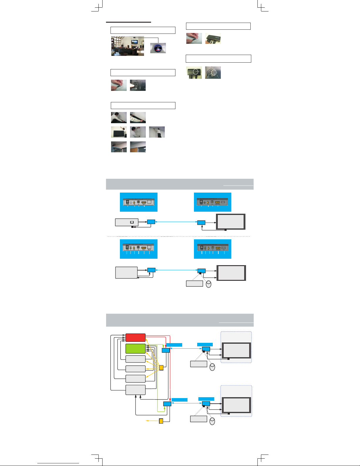
Single Room / Single Source Connection Diagram
OWLink FO RX2800
Power
IR
IN
DLI HDMIto
HDTV
OWLink FO TX2850
Power
IR
OUT
DLI HDMI
IN
Audio
IN
USB to PC
PC
FO2850 Tx
DVI /HDMI
FO2850 Rx
Single fiber w/ DLI
connector
™
USB
Stereo
HDTV
HDMI/HDMI
Stereo
USB KeyBoard
Mouse
OWLink FO RX2850
Power
IR
IN
DLI
HDMI to
HDTV
Audio
OUT
K/M
Multi Room / Multi Source Connection Diagram
DVD
STB
Video
Game
USB
PC
Multi Zone
A/V Receiver
HDMI
HDMI
HDMI
DVI /HDMI
HDMI Switch
4 Input/2Output
HDMI
IR Out
Stereo
HDTV
HDMI/HDMI
Stereo
USB KeyBoard
Mouse
Single fiber w/ DLI
connector
™
HDMI
Stereo
Stereo
Stereo
Zone 2
Stereo
HDTV
HDMI/HDMI
Stereo
USB KeyBoard
Mouse
Single fiber w/ DLI
connector
™
USB
Zone 2
Bedroom/Home Office
IR Out
Zone 1
Stereo
To all devices
FO2850 Tx
FO2850 Rx
FO2850 Tx
FO2850 Rx
Zone 1
Living/Family Room
*
IR Connecting
Block
*
IR Connecting
Block
*
Compatible w/ XANTECH
( )
IR Sensor
IR Sensor
STEP 3: Secure DLI Fiber Optic Cable to the wall, ceiling,
or in the wall.
™
Secure thetransparent fiber optic cable to the floor base board ...
STEP 4: Connect DLI Fiber Optic Cable to FO 2800 TX /
FO 2850 TX
™
Removedust cover cap
from theother end of DLI
connector
™
Connect DLI fibercable
to FO2800 TX /FO 2850 TX
™
Run andsecure the transparent fiber optic cable through the cracks of doors ...
Secure thetransparent fiber optic cable to the wall and ceiling ...
by usingtape , clear silicon, or other adhesive materials.
 Loading...