

Page 1
OWC Mercury Elite Pro Dual Bay
Assembly Instructions
Page 2

OWC Mercury Elite Pro Dual Table of Contents
1 INTRODUCTION
1.1 SYSTEM REQUIREMENTS
1.1.1 Mac® Requirements
1.1.2 PC Requirements
1.2 PACKAGE CONTENTS
1.3 ABOUT THIS MANUAL
1.4 PORT VIEW & CABLE CONNECTIONS
1.5 DETAILED VIEW
1.5.1 Front Activity Light View
2 SYSTEM SETUP
2.1 COVER REMOVAL
2.2 DRIVE INSTALLATION
2.3 RAID CONFIGURATION (FW/USB/ESATA MODEL ONLY)
2.4 FINAL ASSEMBLY
3 FORMATTING
3.1 MACINTOSH FORMATTING
3.2 REMOVING AN EXISTING GUID PARTITION
3.3 WINDOWS FORMATTING
4 TROUBLESHOOTING & TIPS
4.1 TROUBLESHOOTING
4.2 USAGE TIPS
5 APPENDIX
5.1 FAQ
5.2 ABOUT DATA PROTECTION
6 CUSTOMER SERVICE
6.1 BEFORE CONTACTING CUSTOMER SERVICE
6.2 CONTACT INFORMATION
Thank you for purchasing the OWC Mercury Elite Pro Dual!
We’re condent that it will provide years of high performance
service for your storage and backup needs. This manual contains
information on how to install the drives of your choice into the
enclosure, set the desired RAID level (quad interface models only),
format and connect your new storage solution to your computer.
Should you require additional support after reading this manual
along with helpful tips and FAQs, please see the inside back page
for OWC customer support options.
Page 3

OWC Mercury Elite Pro Dual Chapter 1 - Introduction
1 INTRODUCTION
1.1 System Requirements
1.1.1 Mac Requirements
•Minimum PowerPC® G4 CPU, 128MB RAM
•eSATA interface, Mac OS X 10.3 or later
•FireWire® interface, Mac OS X 10.2 or later
•USB 2.0 interface, Mac OS X 10.2 or later
1.1.2 PC Requirements
•Minimum 500MHz Intel® Pentium III CPU, 128MB RAM
•eSATA interface, Windows® XP or later
•FireWire interface, Windows XP or later
•USB 2.0 interface, Windows XP or later
1.2 Package Contents
Item
➀ OWC Mercury Elite Pro Dual
Enclosure
➁ FireWire 400 Cable (*1)
➂ FireWire 800 Cable (*1)
➃ eSATA Cable (*1, *2 (includes 2))
➄ USB 2.0 (A-B) Cable (*1)
➅ Power Supply
➆ Power Supply Cable
➇ Screws for Hard Drives
➁
➀
➃
➆
➅
➂
➇
➄
(*1) Included with Quad Interface Model
(*2) Included with eSATA Passthrough Model
1.3 About This Manual
Firmware, images, and descriptions may vary slightly between this man-
ual and the unit shipped. Functions and features may change depending on the rmware version. Please visit the product webpage for the
most recent specications.
Page 4

OWC Mercury Elite Pro Dual Chapter 1 - Introduction
1.4 Port View & Cable Connections
➀ ➁ ➅ ➆
Cable Connections:
The OWC Mercury Elite Pro family has multiple interfaces to work with
any computer system.
➀ FireWire 400 (1394A) Port - Connect one FireWire 400 port to your
computer using the included cable.
➁ FireWire 800 (1394B) Ports - Connect one FireWire 800 port to your
computer using the included cable and have an extra FireWire 800 port
to add peripherals with!
➂ USB Port - Connect one of your computer’s USB ports to the OWC
Mercury Elite Pro here using the included cable.
➃ eSATA Port - The utmost in speed. If you’re trying to make your OWC
Mercury Elite Pro the fastest it can be, attach an eSATA cable to this port.
➄ On/O Switch - Turn the OWC Mercury Elite Pro on and o here.
➅ DC IN port - Connect the include external power supply to the OWC
Mercury Elite enclosure here.
➆ Security Lock - Attach a security cable to your OWC Mercury Elite
enclosure here and tether it to your desk for theft prevention.
➂ ➃ ➄
➃
➄ ➅ ➆
1.5 Detailed View
1.5.1 LED Indicator
The OWC Mercury Elite Pro has a single cool blue LED at the front of the
hard drive enclosure. It will illuminate blue when powered on, and ash
on drive activity (both reading and writing).
Page 5
OWC Mercury Elite Pro Dual Chapter 2 - System Setup
2 SYSTEM SETUP
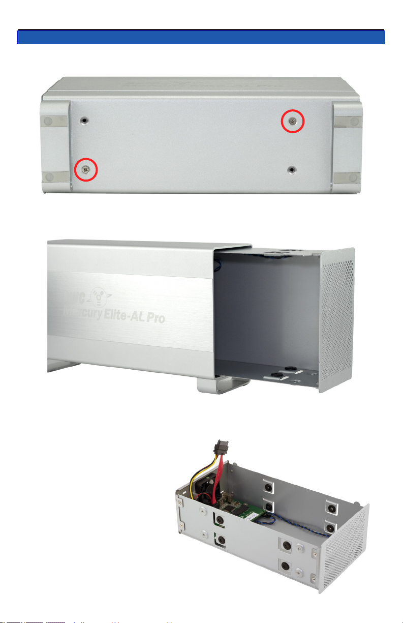
2.1 Cover Removal
Remove the 2 Phillips screws from the bottom of the enclosure
From the rear of the enclosure, push forwards on the interior to slide the
chassis out of the outer shell.
Once the chassis is
removed from the outer
shell, you can begin
installing your hard drive
mechanisms or edit the
settings on your RAID.
Page 6
OWC Mercury Elite Pro Dual Chapter 2 - System Setup
2.2 Drive Installation
(Versions with FireWire & USB)
Begin drive installation by
setting your hard drive into the
chassis, towards the front of
the chassis and slide the drive
onto the black connector on the
green logic board.
(Versions with eSATA ONLY)
Connect one of the multicolored
power cables to the hard drive
you are installing in the lower
drive position, and connect one of the red SATA cables to the hard drive
you are installing in the lower position, and place the hard drive into the
chassis.
Page 7
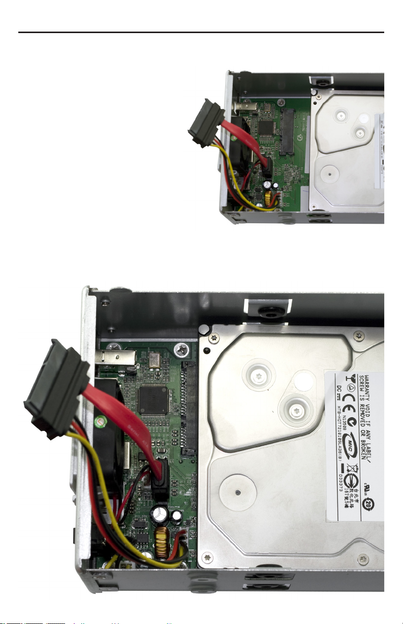
(Versions with FireWire &
USB)
Connect the combined power
and SATA cable to the back of
the hard drive you’re installing
in the top bay. It’s easiest to do
this with the drive positioned
towards the front of the chas-
sis, as shown, and then slide
the drive back to the mounting
position shown below.
(Versions with eSATA ONLY)
Connect one of the multicolored power cables to the hard drive you are
installing in the upper drive position, and connect one of the red SATA
cables to the hard drive you are installing in the upper position, and
place the hard drive into the chassis.
Page 8

OWC Mercury Elite Pro Dual Chapter 2 - System Setup
2.3 RAID Conguration (FW/USB/eSATA Model ONLY)
To change the RAID settings on your FireWire & USB-equipped enclosure, there are three switches located inside the enclosure that need to
be adjusted. You can access the switches by removing the outer case of
the enclosure, or by removing the clip-in fan at the rear.
WARNING: The default RAID mode for the OWC Mercury Elite Pro Dual
is RAID 0. When installing drives into this enclosure, existing data will
be destroyed unless you select independent mode. Conguring a RAID
mode will destroy any data stored on the drives. Back up any important
data before proceeding.
MODE SW#1 SW#2 SW#3
RAID 1 --- OFF OFF
RAID 0 --- OFF ON
SPAN --- ON OFF
INDEPENDENT --- ON ON
2TB MODE ON --- ---
INDEPENDENT - Each hard drive will appear as a separate volume. You
can use dierent models and sizes of hard drive with this mode. NOTE:
Only FireWire and USB connections support independent mode.
SPAN - The drives show up as one large single volume. Spanning is an
array (not RAID) that is written to sequentially across both hard drives.
By itself, it does not provide any performance or redundancy benets.
RAID 0 (STRIPE) - The drives show up as one large single volume. It is
highly recommended to use identical hard drives for this RAID method.
RAID 1 (MIRROR) - The drives show up as one volume, but only 50% of
the total capacity can be used. It is highly recommended to use identical
hard drives for this RAID method. RAID 1 creates an exact copy (or “mirror”) of a set of data on the second drive. This is useful when reliability
and redundancy are more important than capacity. When one drive fails,
it can be replaced and the data will be rebuilt.
2TB MODE - When switch #1 is in the OFF position, the total capacity of
the drives is limited to a maximum of 2.2TB for compatiblity with older
operating systems. NOTE: If setting switch #1 to ON does not initially
allow volume sizes to exceed 2.2TB, do the following: keeping switch
#1 in the ON position, change to a dierent RAID level, then turn on the
unit. Format the new RAID volume, then shut o the unit, change to the
desired RAID level (or independent drive mode), and turn on the unit.
Page 9

OWC Mercury Elite Pro Dual Chapter 2 - System Setup
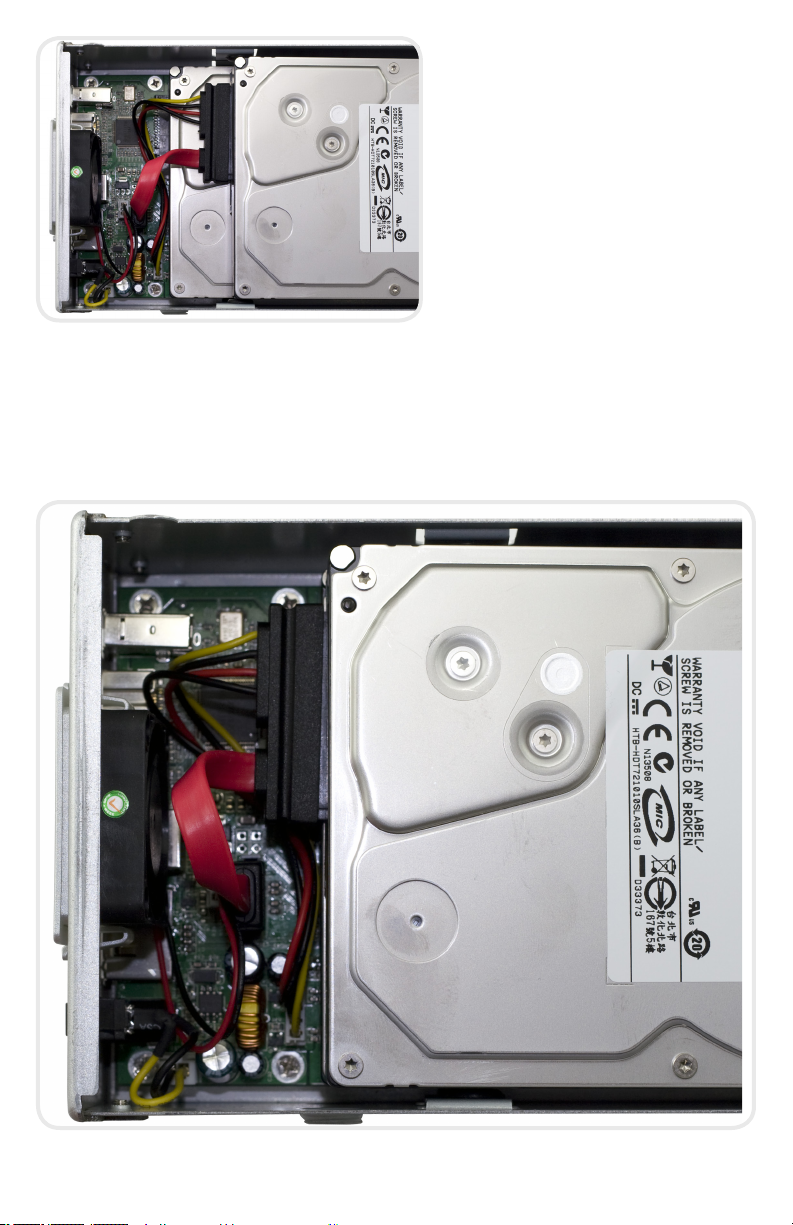
2.4 Final Assembly
Secure the 2 hard drives into the chassis by inserting the 8 Phillips
screws (4 each side) through the black rubber anti-vibration grommets,
and into the hard drives. You may have to lift up a bit on the drives to
get them into position. Firmly tighten the 8 screws to secure your hard
drives into the chassis.
Slide the assembled chassis back into the enclosure from the front to
the rear.
Page 10

OWC Mercury Elite Pro Dual Chapter 2 - System Setup
Place the enclosure on it’s side and insert 4 Phillips screws into the holes
in the bottom of the enclosure to complete assembly of your new OWC
Mercury Elite Pro Dual Bay.
Time to power up your new OWC Mercury Elite Pro Dual Bay!
Turn the drive so you can see the rear ports. Connect the power cable to
the back of the drive, and whichever drive interface cable (FireWire, USB,
eSATA) you plan on using to connect to your computer. Plug the power
brick into the AC power cable (not shown), and power the unit on. You
should hear the drives spin up, and click a couple of times. After about
15 seconds, the drives will be ready to use.
You now need to initialize your drive. If you’re using a Macintosh, the
next pages walk you through that procedure.
If you are using Windows 98/ME/2000/XP/Vista:
You will need to initialize the hard drive before it will show up in “My
Computer”.
For instructions on how to initialize the hard drive please use the link
below. Click on the link that corresponds to the version of Windows you
are using:
http://eshop.macsales.com/tech_center/formatting.cfm
Page 11

OWC Mercury Elite Pro Dual Chapter 3 - Formatting
3 FORMATTING
3.1 Formatting your OWC Mercury Elite Pro Dual on a Macintosh
with Mac OS X
IMPORTANT NOTE: This procedure will erase all data on your hard disk
drives in the OWC Mercury Elite Pro Dual. Back up any important data
before proceeding!
Open the Disk Utility application, which is located in /Applications/
Utilities
➀
Select the device with no volumes attached to it; in this picture, that
would be the 465.8GB OWC Mercury drive, your drive may be of a different size depending on the mechanisms you use. Click once on the
picture of the drive icon next to the text.
➁
Once you’ve selected the OWC Mercury drive, you’ll notice the above
change in the Disk Utility program. Click on the “Erase” tab, next to the
highlighted blue “First Aid” tab in this picture.
Page 12

OWC Mercury Elite Pro Dual Chapter 3 - Formatting
➂
Once on the Erase tab, you need to name the volume you want to
format, and erase it. Name the volume as you want, choose the Volume
format type, (Mac OS Extended (Journaled) is default), and click the
Erase button.
➃
Conrm that you want to erase the volume by pressing the Erase button.
➄
After a few moments, the erase command will complete, and the volume will mount on your desktop. You can quit Disk Utility, and you’re all
set!
Page 13

OWC Mercury Elite Pro Dual Chapter 3 - Formatting
3.2 Removing the GUID Partition Scheme
Only for XP, 2000, ME and earlier. (XP 64-BIT, Vista & Windows 7 can continue to the next section)
If your OWC Mercury Elite Dual was formatted for use on a Macintosh,
it will not be readable by Windows without special software. If you
wish to use your storage solution on a computer running Windows,
you will need to repartition and reformat using the following
instructions.
➀ Go to the DOS command prompt by
selecting “Run” from the Start Menu.
➁ Type in cmd in text box, and hit
the“OK” button.
➂ Type diskpart and hit enter.
➃ Type list disk and hit enter.
➄ Type select disk x replacing x with the number of the disk you want
to reformat. (Typically, you will see an asterisk (*) under “GPT” for the
disk requiring formatting.)
WARNING: The clean command will destroy ALL data on the disk you run it on!!! Be sure there is
nothing you need to keep on your drive before running any of these commands.
➅ Type clean and hit enter.
➆ Type exit and hit enter.
➇ Close the command prompt window.
You may now proceed with formatting the drive.
Page 14

OWC Mercury Elite Pro Dual
Chapter 3 - Formatting
3.3 Formatting your OWC Mercury Elite Pro Dual on Windows 2000
and later
Instructions for other operating systems can be found at http://www.macsales.com/format.
IMPORTANT NOTE: This procedure will erase all data on your hard disk
drives in the OWC Mercury Elite Pro Dual. Back up any important data
before proceeding!
➀ With the drive connected to the computer and
powered on, right click on the “My Computer” icon
and select “Manage” from the menu. The “Initialize
and Convert Disk Wizard” window should appear.
If the Wizard does not appear, expand the Storage
menu by clicking on the plus (+) sign. Then, right
click next to the disk number of the drive that
you have just connected and
click Initialize to bring up the
Wizard.
➁ In the next window, there
should be only one drive
listed. That will be the drive
that you connected via eSATA,
FireWire or USB. Make sure
the box next to the drive
name is checked and click
“Next.”
➂ The Wizard will perform its
tasks, and you will get the fol-
lowing screen. You may click
“Finish.”
Page 15

OWC Mercury Elite Pro Dual
➃ Your drive will
appear similar to
how Disk 1 does
below. Notice that
the space on the
lower right reads
as “Unallocated.”
Right click in this
space and choose
“New Partition.”
➄ The “New Partition
Wizard” will launch.
Click “Next” to con-
tinue.
Chapter 3 - Formatting
➅ Specify your partition type as
“Primary,” and click “Next.”
➆ The wizard will display the maximum partition size for your drive.
It is strongly recommended that
you do not change the default
value. Click “Next”
Page 16

OWC Mercury Elite Pro Dual
➇ If you like, you can specify the
drive letter designation for your
new drive. Otherwise, one will
automatically be assigned. Click
“Next.”
➈ Before you can use the
drive, it must be format-
ted. On most systems
running Windows 2000
or later, it is advisable to
specify the le system as
NTFS. Leave the Allocation unit size as “Default,”
and feel free to give the
drive whatever name you
prefer. Be sure to check
the box “Perform a quick
format”.
If you do not check the “Perform a quick format” box, it will take
several hours for your drive to format. Click “Next.”
Chapter 3 - Formatting
➉ At the end of the
Wizard, you will see a
summary of the information that you specied during the previous
steps. Click “Finish.”
Page 17

OWC Mercury Elite Pro Dual
➀➀ Once you have
nished with the
formatting wizard,
you will see that
your new drive (represented as “Disk
E” in this case) will
display a message
of “Formatting.” This
should only take a
couple of minutes if
you chose the quick
format option.
Chapter 3 - Formatting
➀➁ After a moment
or two, the drive’s
status will change
from “Formatting” to
“Healthy.”
Page 18

OWC Mercury Elite Pro Dual
Chapter 3 - Formatting
➀➂ At this point, you may close the Computer Management window.
Your drive is ready to use and can be found in “My Computer.”
Using your new Storage Solution on both Macs and PCs?
MacDrive™ takes the guesswork out of sharing les. Whether you are transferring
les between home and the oce, a class room lab and your dorm room or even
on the same computer, MacDrive makes it painless.
In fact, you’ll hardly know MacDrive is working.
Once installed MacDrive will automatically give you access to any Mac disk you
pop into your computer. MacDrive even
puts an “apple” icon on the Mac disk, just
to keep things clear.
You can access les on the Mac disk just
like you would with a Windows formatted disk. Open les from the disk or from
within a program. Mac les automatically
get the right icons and le name extensions under both Windows and Mac OS.
Works great with software from Microsoft,
Adobe, Quark, FileMaker, Avid, Digidesign,
Corel, NewTek and more.
You can nd MacDrive at:
http://eshop.macsales.com/search/macdrive
Page 19

OWC Mercury Elite Pro Dual Chapter 4 -Troubleshooting & Tips
4 TROUBLESHOOTING & TIPS
4.1 Troubleshooting
Some of the most simple problems can be traced to power, or connectivity issues. Verify that your cables (both ends!) are properly plugged into the
computer and storage solution. If one connection type does not work, switch
to another interface and try the solution again. If these suggestions do not
work, try the OWC Mercury Elite Pro Dual on a dierent computer, if available
to you.
For further troubleshooting tips, visit our FAQ section online at:
http://eshop.macsales.com/tech_center/FAQ/index.cfm
4.2 Usage Tips
To properly unmount any connected hard drives from your computer, you need to follow a few simple steps.
• For Macintosh systems:
There are multiple methods to umount disks with Macintosh systems.
Either drag the icon for the hard disk you wish to dismount to the trash
can, or you can click the eject icon next to the hard disk name in under the “DEVICES” tab in the sidebar in any nder window, and nally
another method is to right click on the hard drive icon on your desktop
and select “Eject”.
• For Windows systems:
1. Go to the System Tray (located in the lower right corner of your
screen). Click on the Eject icon (a small green arrow over a hardware
image).
2. A message will appear, detailing the devices that the Eject icon controls. i.e. “Safely remove...” Click on this prompt.
3. You will then be given the following message. “Safe to Remove Hard-
ware”. It is now safe to unhook the OWC Mercury Elite Pro Dual.
Page 20

OWC Mercury Elite Pro Dual Chapter 5 - Appendix
5 APPENDIX
5.1 FAQ
Q: How do I format my storage solution?
A: OWC has detailed instructions online for most popular operating
systems, located at: http://eshop.macsales.com/tech_center/fwhdd.cfm
Q: What le system should I choose when formatting my drive?
A: This will depend on how you want to use the drive, but in general we
recommend:
• Mac OS X : HFS + (Mac OS Extended)
• Windows 2000/XP/Vista/7 : NTFS
• For cross-platform compatibility, FAT32 will work, but single le sizes
are limited to 4GB. Other options using 3rd party software exist but are
not covered here.
Q: Will the hard drives spin down when my computer goes to sleep or
into stand-by mode?
A: Yes, they will spin down to save energy. It will take about 30 seconds
to access your data after being in sleep or stand-by mode.
Q: One of my drives failed and I replaced it. Do I need to connect it to
the computer to rebuild the data?
A: No, the rebuild will occur without being connected to the computer
as long as the power is turned on to the enclosure.
5.2 About Data Protection
To ensure that your les are protected and to prevent the loss of your
data, we strongly suggest that you keep two copies of your data: one
copy on your OWC Mercury Elite Pro Dual, and a second copy on either
your internal hard drive or another storage medium, such as an optical
backup, or on a second external hard drive. Any data loss or corruption
while using the OWC Mercury Elite Pro Dual is the sole responsibility of
the user, and under no circumstances will Other World Computing be
held liable for compensation or the recovery of any lost data.
Page 21

OWC Mercury Elite Pro Dual Chapter 6 - Customer Service
6 CUSTOMER SERVICE
6.1 Before Contacting Customer Service
•Read this manual and review Chapter 4: Troubleshooting & Tips.
•Try to conrm the problem is with the hard drive. If you have a second
computer, move the enclosure to that system and verify that the solu-
tion does not function with that machine.
•Visit our tech center for more support suggestions, including FAQs.
http://eshop.macsales.com/tech_center/index.cfm
If you still need support, please have the following available to
you:
• The serial number of the enclosure
• Your invoice number
• What operating system you are using
• Which kind and model of computer you are using
All of this will help speed your support contact along.
6.2 Support Hours Of Operation
8AM - 10PM CT Monday - Friday
9AM - 4PM CT Saturday
By Telephone - (800) 275-4576 (North America only)
International customers please call (815) 338-8685
Live Chat is available 24 hours a day, 7 days a week . Visit:
http://eshop.macsales.com for more information.
Or, you can email. Submit your email at
http://eshop.macsales.com/Service/Tech.cfm
Page 22

Copyrights
Copyright © 2013 Other World Computing, Inc. All rights reserved. No part of this publication may be reproduced, stored in
a retrieval system, or transmitted in any form or by any means, electronic, mechanical, photocopying, recording or otherwise, without the prior written consent of Other World Computing.
Changes
The material in this document is for information only and subject to change without notice. While reasonable eorts have
been made in the preparation of this document to assure its accuracy, Other World Computing assumes no liability resulting
from errors or omissions in this document, or from the use of the information contained herein. Other World Computing re-
serves the right to make changes or revisions in the product design or the product manual without reservation and without
obligation to notify any person of such revisions and changes.
FCC Statement:
Warning! Modications not authorized by the manufacturer may void the user’s authority to operate this device.
NOTE: This equipment has been tested and found to comply with the limits for a Class A digital device, pursuant to Part 15
of the FCC Rules. These limits are designed to provide reasonable protection against harmful interference when the equip-
ment is operated in a commercial environment. This equipment generates, uses, and can radiate radio frequency energy
and, if not installed and used in accordance with the instruction manual, may cause harmful interference to radio commu-
nications. Operation of this equipment in a residential area is likely to cause harmful interference in which case the user will
be required to correct the interference at his own expense.
NOTE: This equipment has been tested and found to comply with the limits for a Class B digital device, pursuant to Part 15
of the FCC Rules. These limits are designed to provide reasonable protection against harmful interference in a residential
installation. This equipment generates, uses and can radiate radio frequency energy and, if not installed and used in accordance with the instructions, may cause harmful interference to radio communications. However, there is no guarantee that
interference will not occur in a particular installation. If this equipment does cause harmful interference to radio or televi-
sion reception, which can be determined by turning the equipment o and on, the user is encouraged to try and correct the
interference by one or more of the following measures:
• Reorient or relocate the receiving antenna.
• Increase the separation between the equipment and receiver.
• Connect the equipment into an outlet on a circuit dierent from that to which the receiver is connected.
Health And Safety Precautions
• Use proper anti-static precautions while performing the installation of your hard drives into this drive enclosure. Failure to
do so can cause damage to your drive mechanisms, and / or the hard drive enclosure.
• Read this User’s Guide carefully, and follow the correct procedure when setting up the device.
• Do not open your hard drive or attempt to disassemble or modify it. Never insert any metallic object into the drive to avoid
any risk of electrical shock, re, short-circuiting or dangerous emissions. Your hard drive contains no user-serviceable parts.
If it appears to be malfunctioning, have it inspected by a qualied Other World Computing Technical Support representa-
tive.
• Never expose your device to rain, or use it near water, or in damp or wet conditions. Never place objects containing liquids
on the drive, as they may spill into its openings. Doing so increases the risk of electrical shock, short-circuiting, re or
personal injury.
General Use Precautions:
• Do not expose the hard drive to temperatures outside the range of 5° C to 40° C (41° F to 104° F). Doing so may damage
the drive or disgure its casing. Avoid placing your drive near a source of heat or exposing it to sunlight (even through a
window). Inversely, placing your drive in an environment that is too cold or humid may damage the unit.
• Always unplug the hard drive from the electrical outlet if there is a risk of lightning or if it will be unused for an extended
period of time. Otherwise, there is an increased risk of electrical shock, short-circuiting or re.
• Use only the power supply shipped with the device.
• Do not use the hard drive near other electrical appliances such as televisions, radios or speakers. Doing so may cause
interference which will adversely aect the operation of the other products.
• Do not place the drive near sources of magnetic interference, such as computer displays, televisions or speakers. Magnetic
interference can aect the operation and stability of your hard drive.
• Do not place heavy objects on top of the drive or use excessive force on it.
• Never use excessive force on your drive. If you detect a problem, consult the Troubleshooting section in this manual.
• Protect your hard drive from excessive exposure to dust during use or storage. Dust can build up inside the device, increas-
ing the risk of damage or malfunction.
• Other World Computing recommends the use of normal glass cleaning products to keep the high lustre nish at it’s nest
with this product. Be sure to not get any moisture inside the holes and if you do, allow time to air dry before use.
• Do not block the ventilation outlets on the rear of the drive. These help to keep your drive cool during operation. Blocking
the ventilation outlets may cause damage to your drive and cause an increased risk of short-circuiting or re.
Copyright ®2006-11 Other World Computing All Rights Reserved. Other World Computing’s Limited Warranty is not transferable and subject to limitations.
OWCMANMAL2ASYR7 09/12/13 SL
 Loading...