

Page 1

MERCURY ELITE PRO DUAL
Assembly Manual & User Guide
Page 2

TABLE OF CONTENTS
INTRODUCTION ...............................................................................................1
1.1 Minimum System Requirements
1.1.1 Apple Mac Requirements
1.1.2 PC Requirements
1.1.3 Supported Drives
1.2 Package Contents
1.3 About This Manual
1.4 Front View
1.4.1 LED Indicators
1.5 Rear view
1.5.1 Rear Features
1.6 Usage Notes
DEVICE SETUP .................................................................................................4
2.1 Quick Start
2.2 Assembly
2.3 RAID Settings
2.3.1 Changing the RAID Mode
2.3.2 RAID Modes
2.4 Drive Failure
2.4.1 Replacing Drives
SUPPORT RESOURCES ............................................................................12
3.1 Formatting
3.2 Troubleshooting
3.3 About Data Backup
3.4 Online Resources
3.5 Contacting Technical Support
OWC MERCURY ELITE PRO DUAL TABLE OF CONTENTS
Page 3
INTRODUCTION
1.1 Minimum System Requirements
1.1.1 Apple Mac Requirements
• USB 3.1 Gen 1: OS X 10.6 or later
• FireWire 800: OS X 10.2 or later
1.1.3 Supported Drives
3.5” SATA hard drives *
* Drives of identical model and capacity are required for RAID 0 and RAID 1.
1.1.2 PC Requirements
• USB 3.1 Gen 1: Windows XP or later
• FireWire 800: Windows XP or later
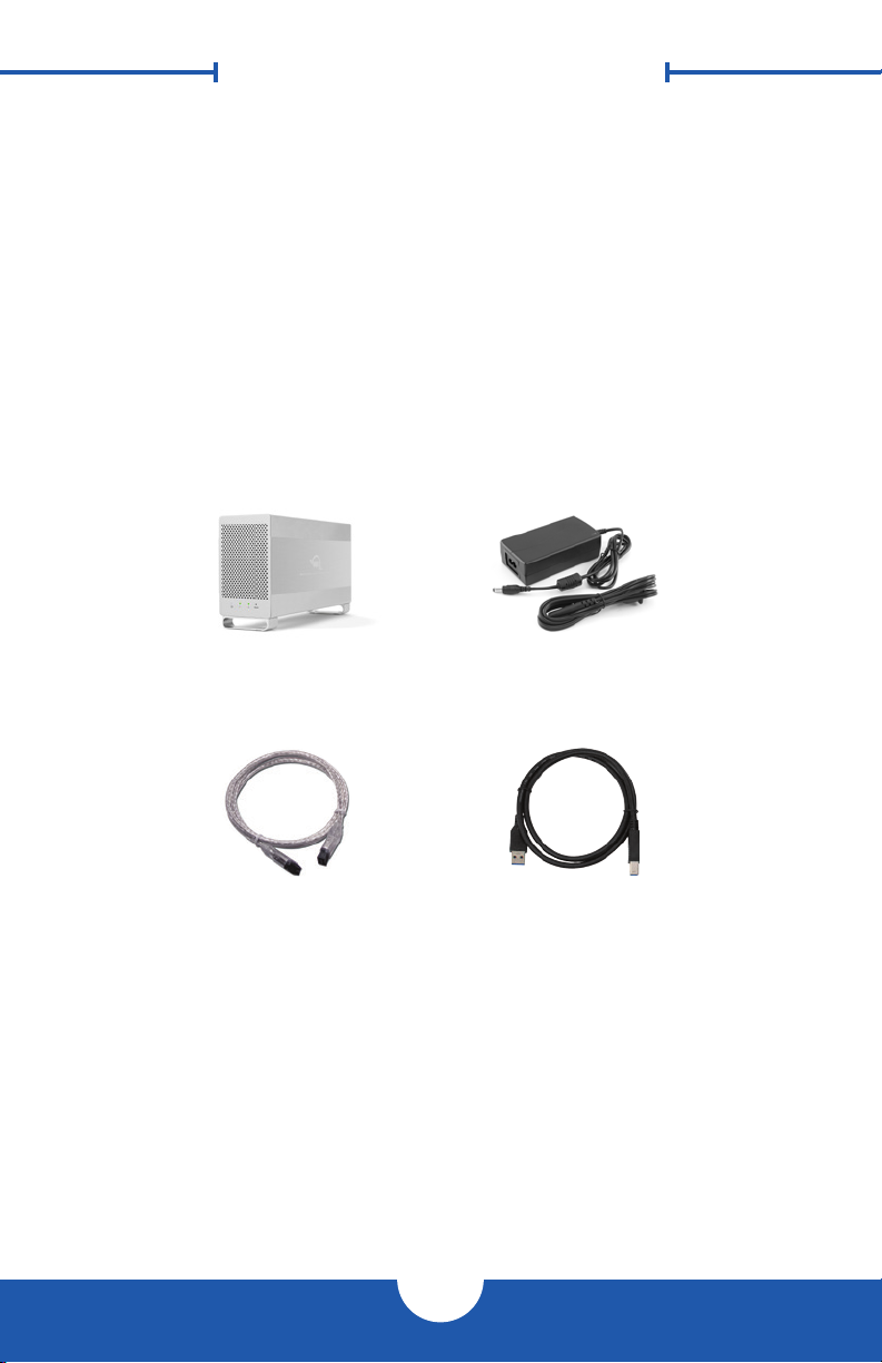
1.2 Package Contents
Mercury Elite Pro Dual Power Supply and
cable
FireWire 800 (1394b)
9-9 pin cable
Not pictured: If the Elite Pro Dual was purchased as an empty enclosure, a packet
of screws is included inside the enclosure.
USB 3.1 Gen 1 (Standard-
A to Standard-B) cable
1.3 About This Manual
The images and descriptions may vary slightly between this manual and the unit
shipped. Functions and features may change depending on the rmware version.
Please visit the product web page for the most recent product specications.
1
OWC MERCURY ELITE PRO DUAL INTRODUCTION
Page 4
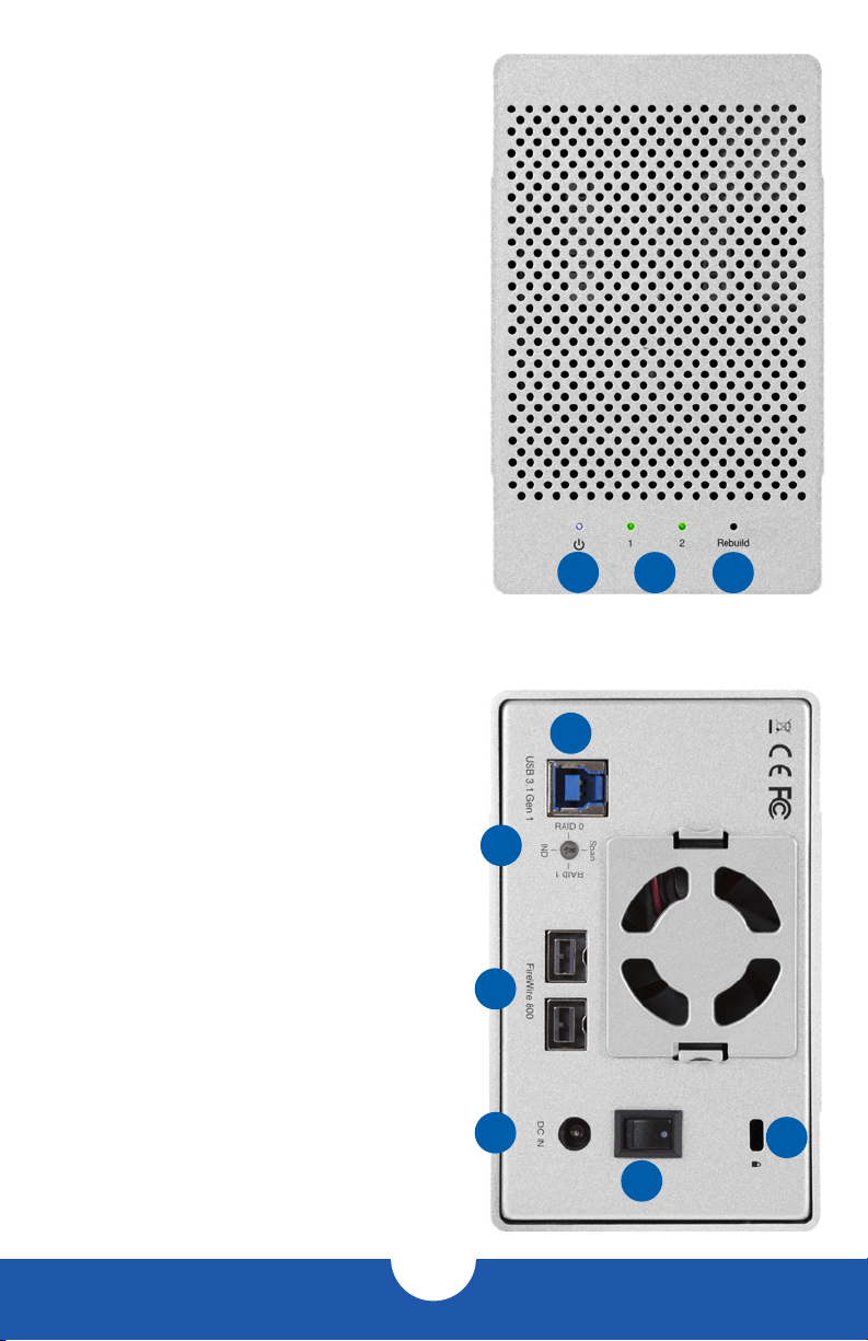
1.4 Front View
1.4.1 LED Indicators
1. Power — This LED emits a solid blue light
when the Elite Pro Dual is powered on.
2. LEDs 1 & 2 — These LEDs represent the
two drives inside the Elite Pro Dual. During
normal activity, each of these LEDs will
blink green when the corresponding drive
is accessed. If one of the drives in the Elite
Pro Dual fails, or if the drive bay is empty,
the corresponding LED will turn solid red.
3. Rebuild — If the Elite Pro Dual is set up
as a RAID 1 and one of the hard drives
is being rebuilt, this LED will blink green
during the rebuild process. The LED that
corresponds to the hard drive being rebuilt
will also blink green.
1.5 Rear view
1 2 3
1.5.1 Rear Features
1. USB 3.1 Gen 1 port — Attach the
included USB 3.1 Gen 1 (Standard-A to
Standard-B) cable here.
2. RAID Dial — Set the RAID mode here.
3. FireWire 800 ports — Attach the included
9-9 pin FireWire 800 cable to one of these
ports and to your computer. Use the other
FireWire 800 port to daisy chain other
FireWire 800 devices.
2
1
3
4. DC IN — Connect the included power
supply here.
5. ON/OFF Switch — Turn power to the Elite
Pro Dual on and o with this switch.
6. Kensington® Security Slot — Connect a
security tether here.
4
5
6
2
OWC MERCURY ELITE PRO DUAL INTRODUCTION
Page 5

1.6 Usage Notes
• Use only one interface (USB 3.1 Gen 1 or FireWire 800) at a time.
• In order for the computer to access volumes larger than 2TB, the operating system
needs to support large volumes (e.g. Windows Vista or OS X 10.4 and above).
• If the enclosure is powered on but there is no active data connection, or if the
computer is sleeping, both drive LEDs will display as solid red. If this happens when
the drive is not sleeping and there is a cable connection present, check both ends of
the data cable to ensure it is securely connected to the enclosure and the computer.
• When you want to change the data connection type from FireWire to USB or vice-
versa, do the following: unmount the volume in the OS, then power o the Elite Pro
Dual. Next switch the data connection, wait 10 seconds, then power on the Elite Pro
Dual again to resume operation.
• For the safe removal of your drive and to ensure that no data is lost, always eject or
unmount the corresponding disk from your operating system before powering o.
There are several methods to unmount disks when using OS X systems.
OS X:
• Drag the icon for the disk you wish to unmount to the trash can.
• Right-click the disk icon on the desktop, then click “Eject”.
• Highlight the disk on your Desktop and press Command-E.
Windows:
1. Go to the System Tray (located in the lower right corner of your screen). Click on
the “Eject” icon (a small green arrow over a hardware image).
2. A message will appear, detailing the devices that the “Eject” icon controls, i.e.,
“Safely remove...” Click on this prompt.
3. You will then see a message that says, “Safe to Remove Hardware.” It is now safe
to disconnect the Elite Pro Dual from the computer.
OWC MERCURY ELITE PRO DUAL INTRODUCTION
3
Page 6

DEVICE SETUP
2.1 Quick Start
Follow the steps below to use the OWC Drive Guide utility to format your Elite Pro
Dual for Mac (OS X 10.4 and later) or Windows (XP and later). If you installed your
own drives, please use the formatting method you are most familiar with or check
Section 3.1 for a link to our online formatting tips.
1. Power on the Elite Pro Dual and plug it into to your computer using the proper data
cable. If you prefer to use a dierent formatting utility, do so at this time and skip
the rest of these steps.
2. The disk will mount and your operating system will display it as “OWC SETUP”.
Open the disk icon to view its contents.
3. Double-click the OWC Drive Guide application.
4. Follow the simple on-screen instructions to complete the formatting process.
Once the formatting is nished the drive is ready to use.
2.2 Assembly
NOTE: these assembly instructions are written for users who purchased the Elite Pro
Dual as an empty enclosure. The instructions show how to open the Elite Pro Dual in
order to change the RAID settings and install drives. If you purchased the Elite Pro
Dual with drives already installed, opening the Elite Pro Dual before the expiration
of the original warranty will VOID the warranty. If you wish to remove or replace the
drives after the expiration of the original warranty, you may do so at that time.
1. Remove the Elite Pro Dual from the retail box and the protective plastic bag. Set
the Elite Pro Dual on its side and look at the bottom of the enclosure. Use a Phillips
screwdriver to remove the two screws, as circled below in red.
4
OWC MERCURY ELITE PRO DUAL DEVICE SETUP
Page 7

2. Once the two screws have been removed, slide the inner chassis out the front
of the outer enclosure, as shown below. Start by pushing on the rear of the inner
chassis, then when you are able to grip the front grill of the inner chassis, pull it
the rest of the way.
3. When removed from the outer enclosure, the inner chassis will appear as shown
below. There will also be a packet of screws inside (not shown). Remove this
packet and use the screws as directed in subsequent assembly steps.
OWC MERCURY ELITE PRO DUAL DEVICE SETUP
5
Page 8

4. Install the rst hard drive (Drive 1), as shown below. Slide the SATA connector on
the hard drive into the black SATA connector (shown in red). Make sure the drive
is rmly seated on the black SATA connector before proceeding. NOTE: the red
SATA cable used to connect the second hard drive has been removed in order
to provide a better image. Do not remove any cables from the Elite Pro Dual.
5. Install the second hard drive (Drive 2), as shown below. Insert the SATA connector
from the red cable into the SATA connector on the hard drive. Make sure the SATA
connectors are rmly seated. NOTE: Make sure that the at red cable is twisted as
shown (below-right) in order to avoid interfering with the exhaust fan.
OWC MERCURY ELITE PRO DUAL DEVICE SETUP
6
Page 9

6. Using eight of the larger screws from the packet you removed in Step 1, fasten
the inner chassis to the hard drives. There are four screw holes on each side of the
inner chassis, as shown below.
7. Slide the inner chassis back into the outer enclosure. Note that while the inner
chassis can slide into both sides of the outer enclosure, there is only one correct
way that will allow the screw holes to line up correctly. To determine the correct
orientation relative to the outer enclosure, turn the outer enclosure on its side and
look at the bottom. The screw holes at the front of the outer enclosure are close to
the silicone feet, while the screw holes at the rear of the outer enclosure are farther
away from the silicone feet.
REAR FRONT
7
OWC MERCURY ELITE PRO DUAL DEVICE SETUP
Page 10

8. Once you have determined the correct orientation, slide the inner chassis back
into the outer enclosure, as shown below.
9. Once the front grill of the inner chassis sits ush with the edge of the outer
enclosure, turn the Elite Pro Dual on its side again to look at the screw holes on
the bottom. You should see that the screw holes in the outer enclosure line up
with the screw holes in the inner chassis. Use the four smaller screws to fasten
the inner chassis to the outer enclosure, as shown below.
The assembly of the Elite Pro Dual is now complete.
8
OWC MERCURY ELITE PRO DUAL DEVICE SETUP
Page 11

IMPORTANT
IMPORTANT
WARNING: Changing the RAID mode will destroy the
data on the drives. Be sure to back up your data rst! See
Section 3.4 for information on proper backup strategies.
2.3 RAID Settings
2.3.1 Changing the RAID Mode
The RAID mode is controlled by a dial on the rear of the
unit, as shown at left. The dial has four positions, each
labeled with a dierent RAID mode. In order to change
the RAID mode, follow the simple steps below.
Adjust the RAID dial so that the arrow is pointing at the
desired RAID mode. Each time the arrow is aligned with
a new mode, you will feel a slight click. A small athead
screwdriver works the best to adjust the dial.
When starting from a power on state, rotate the dial on the back of the enclosure to the
desired RAID mode, then unmount the drive and power o the Elite Pro Dual. Next power on
the Elite Pro Dual. The LEDs on the front will blink for a brief time; once the blinking stops the
drive is ready to use.
When starting from a power o state, rotate the dial on the back of the enclosure to the
desired RAID mode, then power on the Elite Pro Dual. The LEDs on the front will blink for a
brief time; once the blinking stops the drive is ready to use. NOTE: changing the RAID mode
for the Mercury Elite Pro Dual requires an active USB or FireWire connection.
See Section 2.3.2 - “RAID Modes” for more information on each RAID mode that can be
used, and how it diers from the others.
2.3.2 RAID Modes
RAID 0 “Drive Striping” Mode:
The two drives show up as a single large volume with a size equal to the combined
capacities of both drives. RAID 0 is used when speed is the primary objective; it does not
provide data redundancy for protection. The reading and writing of data files is spread
across both drives to gain speed by distributing the workload. This allows for the fastest
data transfer rates, but if one drive fails the whole array becomes corrupted. The data will
be lost. Always maintain a full and separate backup of your RAID 0 data!
RAID 1 “Drive Mirroring” Mode:
The two drives show up as a single volume with a size equal to the capacity of a single
drive from the array. RAID 1 copies (or “mirrors”) the data from the rst drive to the second
drive. This is useful when reliability and redundancy are more important than capacity
or maximum speed. When one drive fails, it can be replaced and the data can be rebuilt
automatically from the other functioning drive. See Section 2.4 for more details on the
drive replacement and rebuild process.
9
OWC MERCURY ELITE PRO DUAL DEVICE SETUP
Page 12

Span Mode:
Both drives show up as a single large volume, but one which functions differently than
RAID 0. The total size will depend on the drives installed; unlike RAID 0 you can use drives
of different capacities. A Span is an array (but not a RAID) in which the data is written
sequentially across the drives. When one drive becomes full, subsequent data is written
to the second drive. This combines the capacities of the drives, but it does not provide
any performance or data redundancy benefits.
Independent Drive Mode
Each drive will appear individually without being combined. If you are using drives of
diering capacity and model, or if you are using only one drive, this is the mode to use.
NOTE: Drives of identical model and capacity are required for RAID 0 and RAID 1.
2.4 Drive Failure
In the event that one of the drives fails, the corresponding drive LED will turn solid
red. If the Mercury Elite Pro Dual was congured as a RAID 0 or Span, the data on
the array is lost and the volume is no longer usable. In a span, only the data stored on
the failed drive is lost, although data recovery software will be required to recover the
data from the other drive in the Span. If the drives were congured independently,
then the data on the drive that did not fail will remain intact.
2.4.1 Replacing Drives
If the Elite Pro Dual is set up as a RAID 1, a drive that has failed can be replaced. The
data will remain accessible via the functioning drive, until the RAID 1 array is rebuilt with
a new drive. If the Elite Pro Dual was purchased with drives already installed and it is
still under warranty, see Section 3.5 to contact OWC technical support and arrange for
replacement. If the unit is outside its warranty or was purchased without drives, follow the
assembly instructions in Section 2.2 to access and replace the failed drive.
If the Drive 1 LED is solid red, the failed drive is the one on the bottom, connected directly
to the black SATA connector on the circuit board (see Section 2.2, step 4). If the Drive 2
LED is solid red, the failed drive is the one on the top, connected using a SATA cable (see
Section 2.2, step 5). IMPORTANT: a failed drive must be replaced with a drive of identical
model and capacity.
Once the drive has been replaced, if the Elite Pro Dual is congured as a RAID 1, the array
will automatically begin the rebuild process when it is turned on. This process may take
several hours to more than a day, based on the capacity of the drives. During the rebuild
process, the LED for the drive being rebuilt (Drive 1 or Drive 2) will blink green, and the
rebuild LED will blink green.
It is recommended to leave the Elite Pro Dual turned on during the entire rebuild process,
but if power is interrupted (or the computer sleeps), the unit will continue rebuilding
automatically when power is restored. Once the rebuild process is complete, the rebuild
LED will turn o and the LED for the rebuilt drive will resume normal activity. See Section
1.4 for more information on the behavior of the LEDs on the front of the Elite Pro Dual.
10
OWC MERCURY ELITE PRO DUAL DEVICE SETUP
Page 13

NOTE: The Mercury Elite Pro Dual needs an active data signal to remain powered on. If
it is disconnected from the computer, or if the computer goes to sleep or turns o, the
device will power o. To minimize the total rebuild time, it is recommended to keep the
device connected to the computer (with the computer powered on), and disable any hard
drive sleep settings on the computer for the duration of the rebuild process.
OWC MERCURY ELITE PRO DUAL DEVICE SETUP
11
Page 14

SUPPORT RESOURCES
3.1 Fo r m at t i n g
For additional formatting information, including instructions on how to format your
Mercury Elite Pro Dual for Mac or Windows, go to: www.owcdigital.com/format
3.2 Troubleshooting
Begin your troubleshooting by verifying that the power cable is connected to the Elite
Pro Dual and to a power source. If the power cable is connected to a power strip,
make sure that the power strip switch is in the ON position. Next, verify that both
ends of the data cable are properly plugged into the computer and the Elite Pro Dual.
If you are still having trouble, try connecting a dierent type of data cable and see
if the Elite Pro Dual works properly; you can also connect the device to a dierent
computer or use dierent cables of the same type. Sometimes the cables themselves
can have aws.
If one of the drive LEDs (Drive 1 or Drive 2) is solid red, then that drive has failed. See
Section 2.4 for instructions on how to proceed. If the Elite Pro Dual is congured
as a RAID 1 and the rebuild LED is blinking, simply wait for the rebuild process to
complete. If the rebuild LED is still blinking after more than 48 hours, contact tech
support for assistance. If problems persist, Section 3.5 provides information for
contacting technical support.
3.3 About Data Backup
To ensure that your les are protected and to prevent data loss, we strongly suggest
that you keep two copies of your data: one copy on your Elite Pro Dual and a second
copy on either your internal drive or another storage medium, such as an optical
backup, or on another external storage unit. Any data loss or corruption while using
the Elite Pro Dual is the sole responsibility of the user, and under no circumstances
may OWC, its parents, partners, and aliates be held liable for loss of the use of data
including compensation of any kind or recovery of the data.
3.4 Online Resources
To access our online knowledge base, which includes topics like migrating your data from an
old drive to a new one, please visit: www.owcdigital.com/faq
12
OWC MERCURY ELITE PRO DUAL SUPPORT RESOURCES
Page 15

3.5 Contacting Technical Support
8am - 8pm (CT) Monday - Friday
9am - 4pm (CT) Saturday
(866) 692-7100 (North America only)
+1 (815) 338-4751 (International)
Live chat is available during normal business hours at:
www.owcdigital.com/support
Email support is available at:
www.owcdigital.com/support
OWC MERCURY ELITE PRO DUAL SUPPORT RESOURCES
13
Page 16

Changes:
The material in this document is for information purposes only and subject to change without notice. While reasonable
efforts have been made in the preparation of this document to assure its accuracy, OWC and its officers and employees
assume no liability resulting from errors or omissions in this document, or from the use of the information contained herein.
OWC reserves the right to make changes or revisions in the product design or the product manual without reservation and
without obligation to notify any person of such revisions and changes.
FCC Statement:
Warning! Modications not authorized by the manufacturer may void the user’s authority to operate this device.
NOTE: This equipment has been tested and found to comply with the limits for a Class B digital device, pursuant to Part 15
of the FCC Rules. These limits are designed to provide reasonable protection against harmful interference in a residential
installation. This equipment generates, uses and can radiate radio frequency energy and, if not installed and used in
accordance with the instructions, may cause harmful interference to radio communications. However, there is no guarantee
that interference will not occur in a particular installation. If this equipment does cause harmful interference with radio or
television reception, which can be determined by turning the equipment off and on, the user is encouraged to try to correct
the interference by one or more of the following measures:
• Reorient or relocate the receiving antenna.
• Increase the separation between the equipment and receiver.
• Connect the equipment to an outlet on a circuit different from that to which the receiver is connected.
Health And Safety Precautions:
• Use proper anti-static precautions while performing the installation of your hard drives into this drive enclosure.
Failure to do so can cause damage to your drive mechanisms and/or the hard drive enclosure.
• Read this user guide carefully and follow the correct procedures when setting up the device.
• Do not attempt to disassemble or modify the device. To avoid any risk of electrical shock, fire, short-circuiting or dangerous
emissions, never insert any metallic object into the device. If it appears to be malfunctioning, contact technical support.
• Never expose your device to rain, or use it near water or in damp or wet conditions. Never place objects containing liquids
on the drive, as they may spill into its openings. Doing so increases the risk of electrical shock, short-circuiting, fire or
personal injury.
General Use Precautions:
• To avoid damage, do not expose the device to temperatures outside: 41º — 107º F (operating) or
-40º — 149º F (non-operating)
• Always unplug the device from the electrical outlet if there is a risk of lightning or if it will be unused for an extended
period of time. Otherwise, there is an increased risk of electrical shock, short-circuiting or fire.
• Do not use the device near other electrical appliances such as televisions, radios or speakers. Doing so may cause
interference which will adversely affect the operation of the other products.
• Do not place the device near sources of magnetic interference, such as computer displays, televisions or speakers. Mag-
netic interference can affect the operation and stability of hard drives.
• Do not place heavy objects on top of the device.
• Protect your device from excessive exposure to dust during use or storage. Dust can build up inside the device, increasing
the risk of damage or malfunction.
• Do not block any ventilation openings on the device. These help to keep the device cool during operation. Blocking the
ventilation openings may cause damage to the device and cause an increased risk of short-circuiting or fire.
• For up-to-date product and warranty information, please visit the product web page.
Copyrights and Trademarks:
No part of this publication may be reproduced, stored in a retrieval system, or transmitted in any form or by any
means, electronic, mechanical, photocopying, recording or otherwise, without the prior written consent of OWC.
© 2016 OWC. All rights reserved.
OWC is trademark of New Concepts Development Corporation, registered in the U.S. Patent and Trademark Office
and/or in Canada. The OWC logo is a trademark of New Concepts Development Corporation. Apple, Mac, and
OS X are trademarks of Apple Inc., registered in the United States and/or other countries. Windows and Windows
Vista are either registered trademarks or trademarks of Microsoft Corporation in the United States and/or other
countries. Other marks may be the trademark or registered trademark property of their owners.
OWCMANMEPD562UFR2 05/20/16 DM
OWC’s Limited Warranty is not transferable and subject to limitations.
Copyright 2016 OWC. All Rights Reserved.
 Loading...