

Page 1
OWC Mercury Optical Drives
Installation Instructions
For PowerBook G4 15” Models
Page #1OWC Mercury Optical Drives Installation Manual
Page 2
Thank you for purchasing an OWC Mercury Optical drive from
Other World Computing!
Please use this reference guide to install your new optical drive into your PowerBook G4
15” “Titanium”.
Before getting started, you will need the following:
• A well lit clean work space approximately 3’x2’
• A soft cloth or rubber mat to place the PowerBook on while working on it
• A #1 Phillips Screwdriver
• A Torx T-8 Screwdriver
• A Torx T-6 Screwdriver (some models w/ combo drives installed)
• A blank CD-R disc
• A blank DVD-R disc (DVD-R optical drives only)
You will need to observe static safe precautions while performing this installation,
just like you would for installing memory into your computer. Refer to your original
PowerBook manual for those steps.
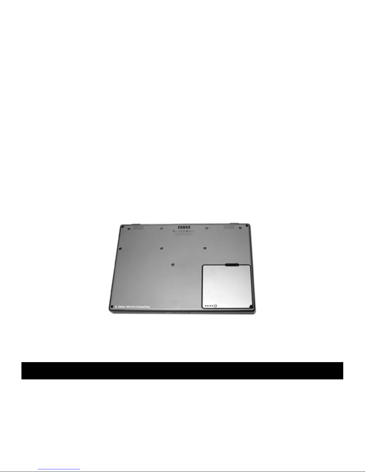
Bottom side of a PowerBook G4/500MHz. Some systems will look different and have screws in different
locations, although the objective is the same.
Before beginning, make certain your PowerBook is shut down. You cannot
perform this upgrade if the computer is in sleep mode.
Start by turning your PowerBook over on it’s top. You may want to place the computer
on a soft cloth or a rubber mat to keep it from sliding around while you perform
this upgrade. A mouse pad works well, just be sure to not scratch the top of your
PowerBook. Take a few moments and align all of the components and tools you will need
to perform this upgrade so that you don’t have to move around much while doing the
upgrade. You will nd that if you don’t have to reach very far for an item, it will allow
you to concentrate more.
Page #2OWC Mercury Optical Drives Installation Manual
Page 3
Remove the battery from the PowerBook and place it aside.
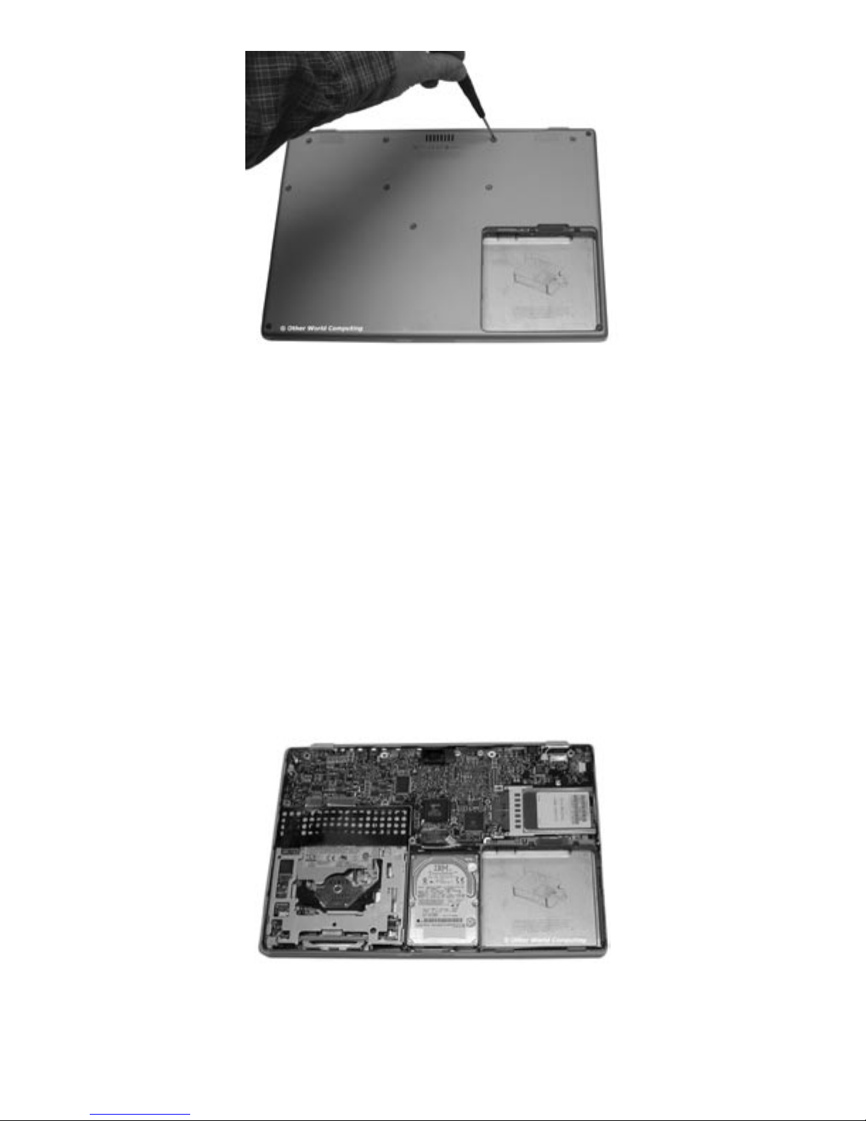
Remove the screws from the bottom of the computer. Depending on the model of
computer you have, it will either use #1 Phillips screws or Torx T-8 screws. Some of
these can be difcult to remove, be patient and use even force to unscrew them. Do
NOT slip and either damage the screw head or scratch the bottom of the PowerBook.
If you own a PowerBook G4 400 - 667MHz(VGA)
system without a combo DVD-CD/RW drive installed,
please continue with this section.
For 667Mhz(DVI) - 1GHz systems, or for machines
that already have a combo DVD-CD/RW drive, please
turn to page 11.
Gently remove the bottom of the PowerBook and expose the logic board / HD / CD
Drive. Note on the bottom left is the object of this upgrade, the CD-ROM drive. You may
want to take a few moments and remove any dust or lint that has become trapped inside
of the computer, especially at the top center, the cooling fan.
Page #3OWC Mercury Optical Drives Installation Manual
Page 4
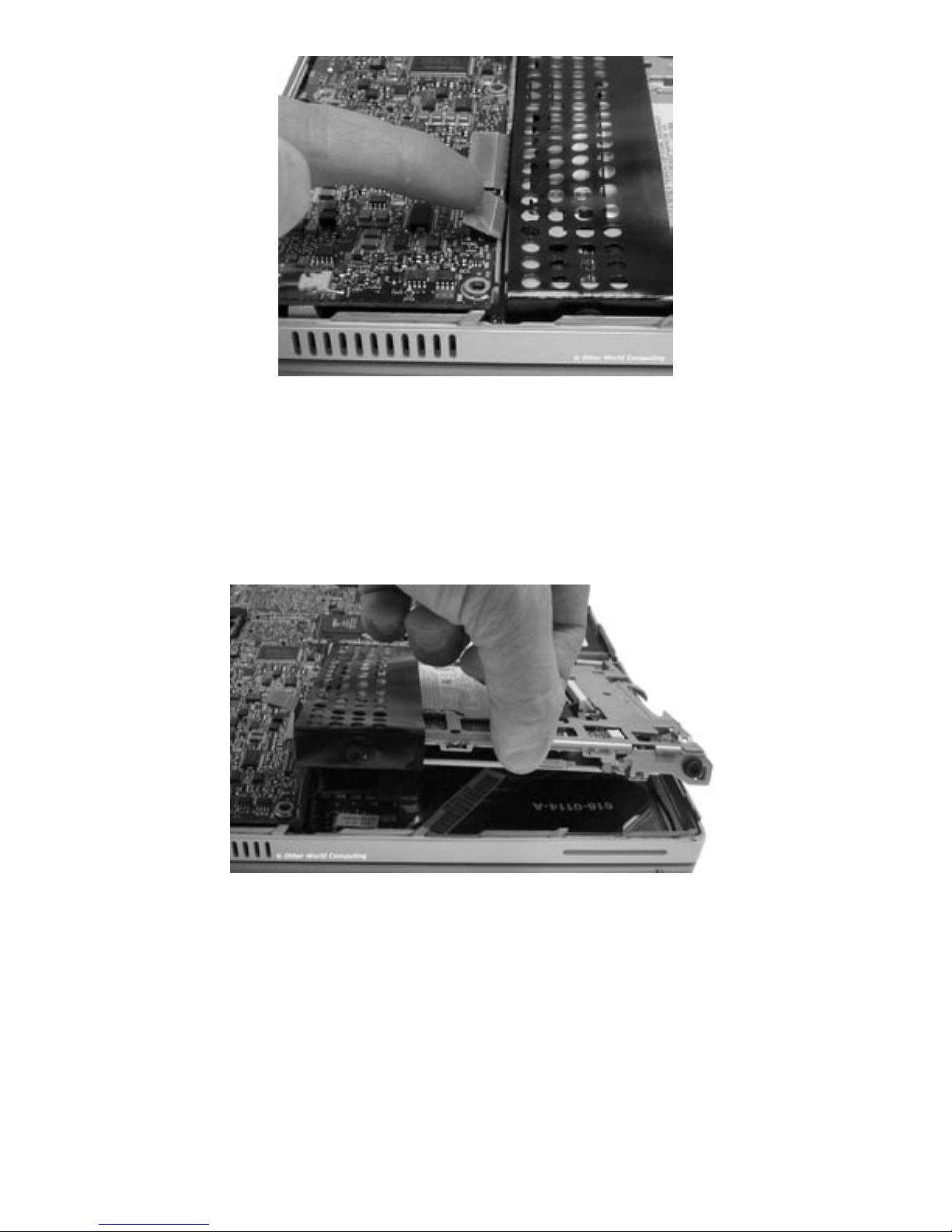
Begin removing the CD-ROM drive by detaching the cable that controls it from the main
logic board as shown. You may nd a yellow piece of tape covering the cable you need to
remove, gently peel it off of the logic board, you can reattach it once the installation is
complete. Your ngernail is probably the best choice to remove this cable from the logic
board, you only need lift it up enough to dislodge it from the connector.
Once the cable has been unhooked, you can then grasp the side of the CD-ROM drive as
shown and gently lift it out of the computer. You’re lifting on the side of the drive, not
the front. Notice the 2 screws and rubber grommets attached to the CD-ROM drive, they
aren’t captive held into the frame of the computer, they are held in by compression once
the bottom is attached to the computer.
Lift the drive up and pull toward you, the entire mechanism will slide out.
NOTE: If you feel resistance, you may have a piece of tape holding the thin black
plastic shield down at the rear of the drive. The only way to remove this adhesive is to
physically break the plastic shield, it’s not very difcult to do. If you’re lucky, you can
peel the plastic away from the adhesive but don’t be concerned if you break the plastic
shield.
Page #4OWC Mercury Optical Drives Installation Manual
Page 5
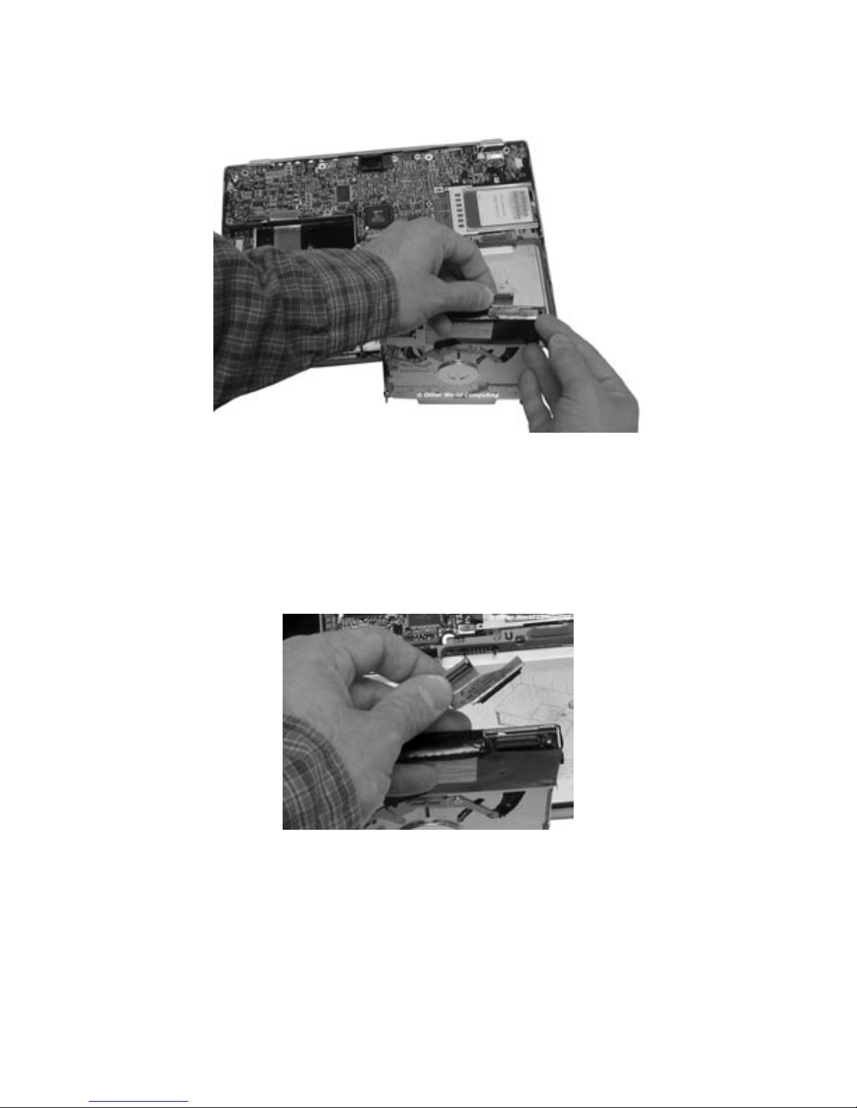
Take the CD-ROM drive and turn it so you can see the cable attached to the back of it.
Gently use your ngernails to rock the cable gently, removing it from the connector.
Set the cable aside.
Another picture of the cable being removed, showing the connector in more detail.
Page #5OWC Mercury Optical Drives Installation Manual
Page 6
Use the Torx T-8 screwdriver to remove the 4 screws and grommets that are at the
corners of the drive. You will notice that the screws are all identical, but there are 3
different types of grommets.
• Two are half-moon shaped and go on the left side of the drive (they are the ones
that are compressed to hold in place when the lid is closed).
• One is a standard round washer that goes at the front right of the drive, right next to
the hard drive.
• One is a captive grommet, which is round and ts into a hole at the top right of the
CD bay.
Place these screws and grommets in order when you remove them to avoid having to
determine which one goes where upon reassembly.
Once the screws have been removed, slide the thin plastic drive shield off of the
CD-ROM mechanism. If you had to tear any part of it to remove because of it being
stuck inside of the machine, take a moment and examine where it was torn and use a
bit of tape to repair it.
Page #6OWC Mercury Optical Drives Installation Manual
Page 7

Side-by-side comparison of two drives. An OWC Mercury Ti Combo on the left, the CDROM/DVD-ROM drive just removed on the right.
Slide the plastic drive shield over the rear of the new OWC Mercury Optical drive. This
usually takes two hands to get it in place. The shield will fully cover the rear of the drive
and the screw holes will be visible once you have it in place all the way.
Align the cable you removed and fully seat it into the OWC Mercury Optical drive’s
connector. This will also help hold the plastic shield in place while you install the screws
and grommets.
Page #7OWC Mercury Optical Drives Installation Manual
Page 8

Insert the 4 Torx T-8 screws into the OWC Mercury Optical drive and place their
grommets over the screw heads. Once again, the locations are:
• Two are half-moon shaped and go on the left side of the drive (they are the ones
that are compressed to hold in place when the lid is closed).
• One is a standard round washer that goes at the front right of the drive, right next to
the hard drive.
• One is a captive grommet, which is round and ts into a hole at the top right of the
CD bay.
The two grommets / washers on the right side are universal in orientation, because
they are round. The two grommets on the left side are half-moon shaped and the moon
(larger portion) should be facing up as shown in this picture. The drive slides down onto
the smaller portion of the grommet and if improperly installed, the case will not close on
the PowerBook.
Page #8OWC Mercury Optical Drives Installation Manual
Page 9

Now that you have the OWC Mercury Optical drive prepared to reinstall into the
PowerBook, take a moment and look inside of the CD-ROM bay where the new drive will
be placed. Note the two holes that are highlighted in this photograph. The grommet and
washer will be placed into these holes when you install the new drive. Note that the rear
hole is deeper than the front, as the front will not protrude into the hard drive bay when
installed.
Set the new drive into the bay (old drive is pictured, but the t is the same). NOTE:
The label side of the drive will be DOWN, reversed from what the original drive was. Be
certain when you have the holes on the right side of the bay lined up and pivot the new
drive down into the bay that you have the controlling cable ush with the rear of the
drive, otherwise it will catch and impede your movement of the drive downward.
Page #9OWC Mercury Optical Drives Installation Manual
Page 10

Once your new OWC Mercury Optical drive is inserted fully into the CD bay, insert the
controlling cable onto the connector on the logic board. Be sure that the cable is fully
lined up, it does take a bit of adjustment so it will seat into the connector fully. If your
system had yellow tape covering the two connectors, reattach it now.
Your new OWC Mercury Optical drive should t snugly into the drive bay. Run your
ngers along the perimeter of the drive to be sure that it fully seated into the bay, it
should not protrude from the left side at all, the half-moon grommets will settle down
onto the posts that align the height perfectly.
Please turn to page 20
Page #10OWC Mercury Optical Drives Installation Manual
Page 11

Installation into a 667MHz (DVI) or later with combo drive.
Upon removing the bottom shell of the PowerBook, you will see the optical drive on the
left side of the computer. Turn the machine so the drive is oriented facing you, as shown
in this picture. There are a number of cables and connectors you need to unhook to
remove this drive. The cards attached to the drive brackets are a modem (left) and the
inverter board for the display (right).
Begin removing the drive by gently lifting up on the ribbon cable attached to the inverter
board, circled here.
Page #11OWC Mercury Optical Drives Installation Manual
Page 12

Detach the ribbon cable from the inverter board and then from the logic board - the two
positions you remove the cable from are shown circled in this picture. Set the inverter
ribbon cable aside.
Unplug the white and pink cable from the inverter board by pulling gently straight back
towards the modem, the cable is shown unplugged in this picture. The wires are very
exible silicone coated, do not pinch or cut them as they carry power to the LCD display.
Page #12OWC Mercury Optical Drives Installation Manual
Page 13

At the top of the drive you will see a at ribbon cable attached to the main logic board,
it may be covered by a yellow piece of kapton tape. If it is, remove the tape gently (you
will reuse it), and lift up on the ribbon cable from the logic board side gently, as shown.
Look back at the outside of the drive assembly and you will see two more connectors
that need to be detached. Unplug the ribbon cable from the logic board (it goes to the
modem, underneath the drive), and also the 2 wire cable from under the edge of the
black plastic cover on the modem card. That cable will need to be pulled straight out of
it’s connector toward the back of the PowerBook.
Page #13OWC Mercury Optical Drives Installation Manual
Page 14

You are now ready to physically remove the drive from the PowerBook. Start by gently
lifting up on the drive where the modem and inverter boards are at, angling the drive
from the outside. The 2 rubber grommets that the drive rests on will allow the drive to
lift freely on the outside, but not the inside. The inside grommets are captive and t
inside holes in the frame and you cannot lift from the middle of the computer.
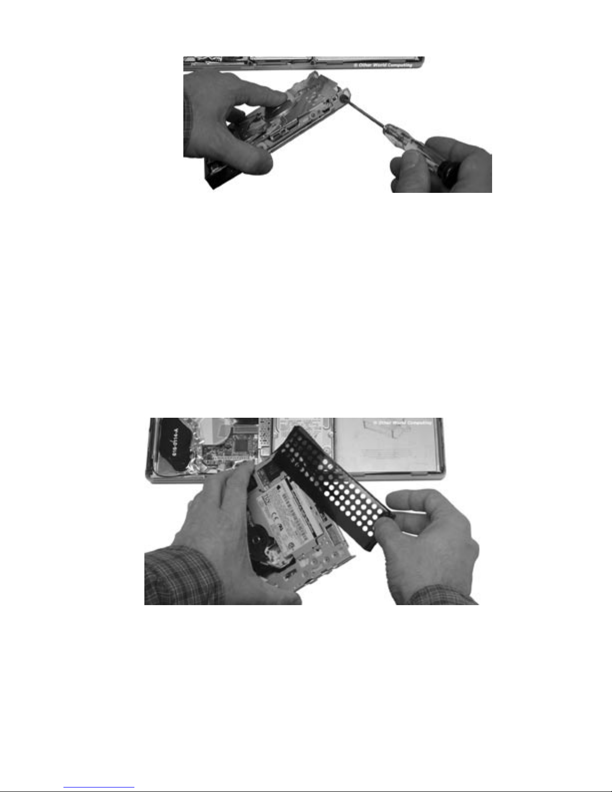
Once the drive is free of the machine, set it on a at surface and remove the 4 Torx T-6
screws circled in this picture that attach the cards to the frame.
The inverter board will lift straight up off of the frame, set it aside. The modem card
will also lift straight up and off of the frame, but the ribbon cable needs to be gently fed
through the bottom half of the frame, do not cut or pinch the cable while doing so. You
can remove the cable itself to do this, but you do not have to - your choice.
Turn the drive around and remove the two Phillips screws that attach the small left
frame to the drive. Set all parts aside in a safe place.
Page #14OWC Mercury Optical Drives Installation Manual
Page 15

Remove the two Phillips screws from the large right metal frame. Notice that the screw
on the left in this picture is a zero draft head - very at, and it will need to be put
back into this hole, otherwise the modem card will not t ush back into place upon
reassembly. Set the frame aside.
Remove the drive connector cable from the back of the drive and set it aside.
Page #15OWC Mercury Optical Drives Installation Manual
Page 16

Turn the original drive on it’s back and point the slot toward you as shown in this picture.
Using a small thin straight screwdriver, or a paperclip, press gently on these two release
tabs circled in this picture. You will nd two more tabs on the bottom side of the drive
(pictured below), and also one on the side. Once you release the tabs, you will see the
other capture points and the removal is simple. Be patient, and do not break the tabs.
Remove and place the feed slot onto the new drive in the same way you removed it from
the old drive, starting with the side tab and hinging the slot onto the drive mechanism,
locking it into place.
Page #16OWC Mercury Optical Drives Installation Manual
Page 17

Begin assembling the new drive by placing the large right frame on the new drive.
Attach the small zero draft screw on the left, and the regular screw on the right (circled
with the large circles above). Gently slide the modem’s ribbon cable through the slot
shown above, placing the modem on the screw risers circled on the left. Do the same
with the inverter board, placing it on the right, with the power connector toward the
modem card.
Reattach the 4 Torx T-6 screws you removed from the boards back onto the assembly,
securing the cards in place.
Page #17OWC Mercury Optical Drives Installation Manual
Page 18

Attach the drive controller cable to the back of the new drive as shown. It will t ush
once in place.
Reattach the small bracket to the left side of the drive using the Phillips screws you
removed from it. The old drive is shown in this picture, installation is identical.
Inserting the drive into the PowerBook
Take the assembled drive components and place it into the PowerBook, label side down,
with the modem and inverter board towards the outside.
You will need to place the rubber grommets from the frame on the inside portion of the
drive mechanism into the holes in the PowerBook chassis that line up with the drive,
and pivot the new drive downward into the chassis. Once inserted, the rubber grommets
on the outside portion of the frame will rest on their mounting pegs. Be sure the drive
is straight, and do not use force to insert the drive, it will slide right into place without
resistance if installed properly.
Page #18OWC Mercury Optical Drives Installation Manual
Page 19

Start by attaching the drive controller cable on the back of the drive to the logic board.
If there was a yellow piece of Kapton tape when you removed that cable, reattach it
now.
Then, following the numbers here, attach the cables you removed back onto the
components.
1. Inverter power (routing the cable neatly around the drive, as shown)
2 & 2a. Inverter ribbon cable (you removed it from the machine originally)
3 & 3a. Modem ribbon cable
4. 2 wire cable from modem card (under black plastic cover)
Another picture of the inverter pink & white cord, routed nicely around the drive
mechanism.
Page #19OWC Mercury Optical Drives Installation Manual
Page 20

Place the bottom back onto your PowerBook and line up all of the screw holes. We
recommend partially inserting each screw only enough to line the hole up, and
proceeding to the next screw. Frequently PowerBooks will have a screw or two that are
extremely difcult to get seated fully, if you encounter resistance while inserting the
screws, you can usually press the case bottom back toward the rear a bit more and
alleviate the pressure on the screw, allowing it to be tightened for a snug t.
Tighten the screws in a rotation starting with the inside screws, as directed by your
original Apple PowerBook manual.
Once the bottom is reattached, you’re ready to try out your new OWC Mercury Optical
Drive! Boot the system up and insert a blank CD-R disc - you should be greeted with
a dialog box asking what you wish to do with it. The OWC Mercury Optical Drive works
natively with all of your favorite creation applications!
Entire contents copyright ® 2003 Other World Computing all rights reserved. JD 8/20/03
Page #20OWC Mercury Optical Drives Installation Manual
 Loading...