

Page 1
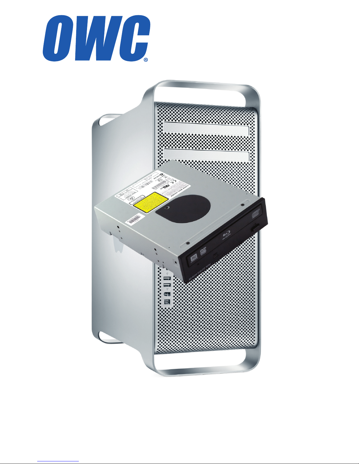
Mac Pro
SATA Optical Drive
Installation Manual
Page 2
Page 1
Thank you for purchasing the Other World Computing Mac Pro
Serial ATA Optical Kit! This guide will walk you through the installation process step by step and get you up and running using your
new optical drive quickly.
Installation of the optical drive is straightforward but does contain
some dicult procedures. We highly recommend you thoroughly read
through this manual before beginning the installation to avoid any surprises along the way.
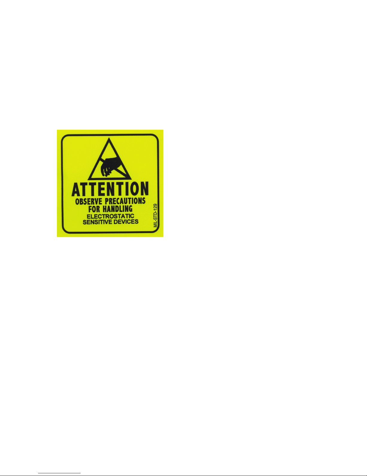
ATTENTION!
You will be working in
close proximity to static
sensitive components. Take
precautions to not build up
static electricity.
You will need the following tools to perform this installation:
• A Phillips P1 Screwdriver
• A Phillips P0 Screwdriver
• You may need a thin pair of needlenose pliers, or a pair of hemostats,
depending on your Mac Pro and it’s time of manufacture.
Bring your Mac Pro up to a desktop level so you can work on it. You’ll be
leaving it in an upright position for this installation, but you won’t want
to be on the oor to do this job.
Page 3

This manual is broken into 3 parts.
• If you own a Mac Pro 667MHz system made between August, 2006
and January, 2008, turn to page #3
• If you own a Mac Pro 800MHz system made after January, 2008,
turn to page #12
• The installation of the optical drive is the same for both of these
models. That portion of the assembly guide begins on page #16
TABLE OF CONTENTS: PAGE #
Mac Pro 667MHz Installation 3
Mac Pro 800MHz Installation 12
Optical Drive Installation (All Models) 15
Page 2
Page 4
Page 3
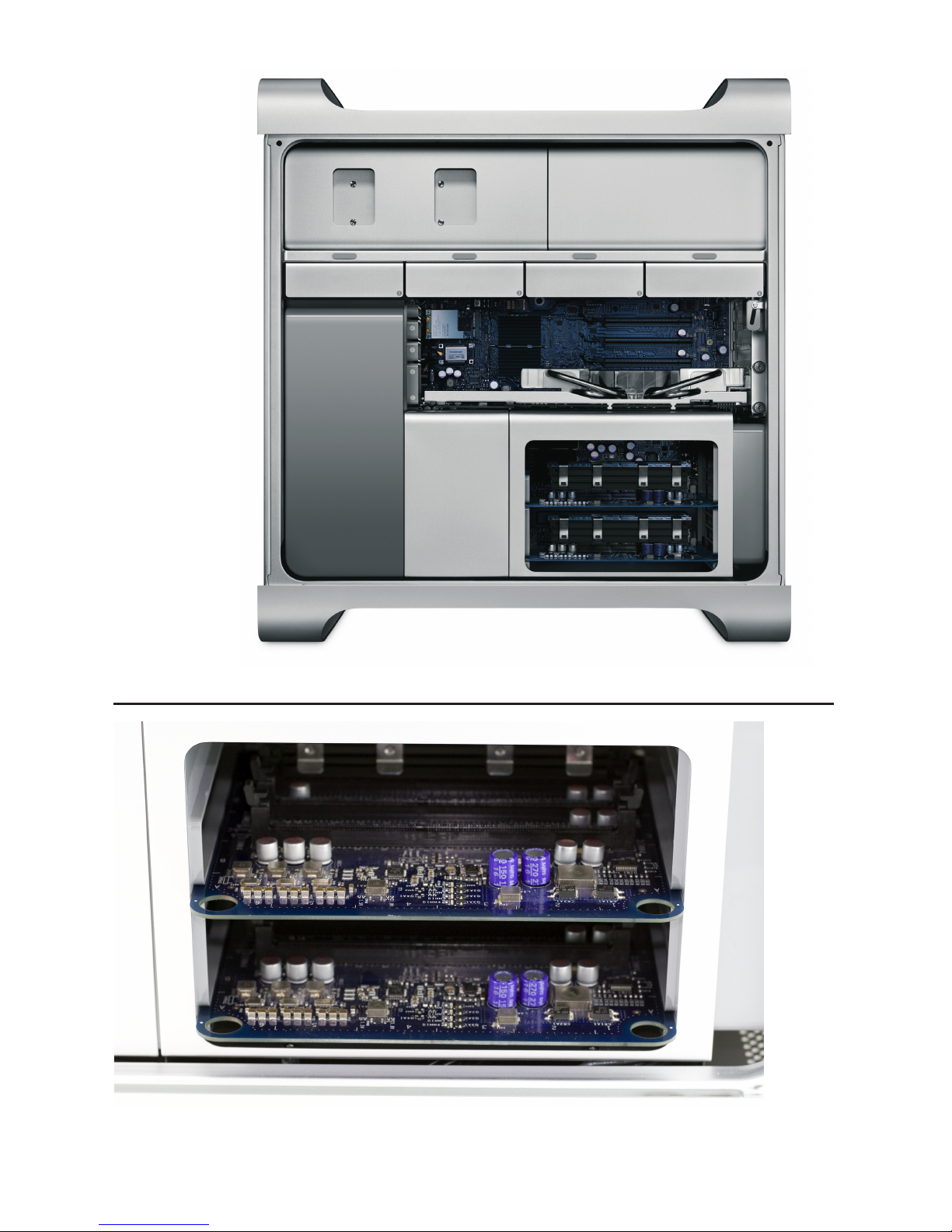
Begin by removing the side door on your Mac Pro.
On the lower right, nd the memory bay.
Mac Pro 667MHz - Cable Installation
Page 5
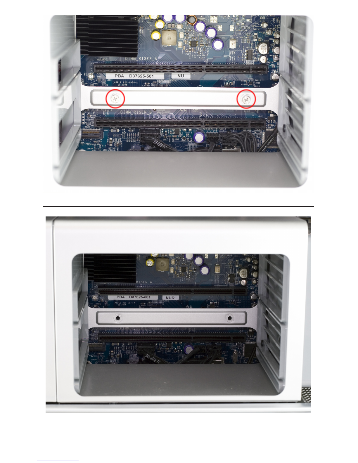
Remove the 2 memory riser cards, exposing the 2 Phillips screws shown here.
Remove the 2 Phillips screws. They are long and extend through the logic board and
into the back of the computer.
Page 4
Page 6
Page 5
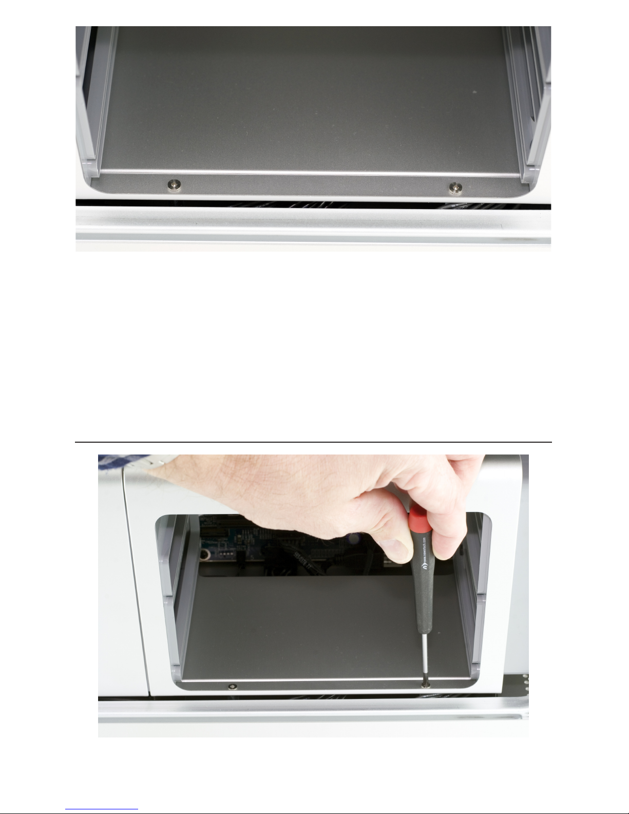
At the bottom of the memory bay, there are 2 more Phillips screws. They are a smaller
head than the ones inside the memory bay that you just removed. Use a Phillips #0
screwdriver to remove the screws.
There is one problem. On many machines, the screws were improperly installed. Instead of using loctite on the screw stando, Apple used loctite on the screws themselves, into the standos - without loctite on the standos that thread into the Mac
Pro’s chassis.
This means, when you try and remove the screws, the standos themselves that the
screws are screwed into turn. You may need to use a very thin pair of needlenose pliers, hemostats, or even a thin at blade screwdriver to hold the hex-shaped stando
tight, while you loosen the Phillips screws.
A photo of this task being made look easy, at least if your screws are not improperly
installed as described above. Try and not strip the Phillips screw heads.
Page 7

Make sure that the locking latch on the back side of the Mac Pro is lifted up. Then,
remove all 4 of the drive bays and set them aside.
Look inside the PCI Express bay at the top right of the Mac Pro. You’ll need to remove
items from this location next.
Page 6
Page 8

Page 7
Using a Phillips P0 screwdriver, loosen the PCI Express cover retaining plate and
remove it. There is a tab at the top that the metal plate latches into, you’ll need to
unscrew the 2 screws and slide the plate down out of the tab.
Once the metal retaining plate is removed, remove the top PCI Express dead plate
cover from the top slot as shown. Set the dead plate cover aside, you’ll be using it in a
future step.
Page 9

Remove your PCI Express video card. At the rear of the PCI Express slot, there is a small
plastic tab that you need to lift up to unlock the PCI Express card. While doing this, pull
gently on the card itself toward you and it will come free. Set the video card aside.
Immediately to the left of the PCI slots, at the top of the logic board, you will see this
Phillips screw. Using a Phillips P0 screwdriver, remove it.
Page 8
Page 10

Page 9
Take the memory bay and gently move it to the right, towards the back of the computer. You’ll be able to gently shake it and it will pop loose and move just enough to
expose a gap between the processor cover and the memory bay as shown.
Once the memory bay is moved, you can pull out on the bottom of the processor
cover on the bottom right, and gently remove it from the computer. It hinges up and
to the right as shown. It locks into the fan shroud on the left fairly tight.
Page 11

A view of the processor heatsinks with the cover removed.
Some later model Mac Pro systems, especially 8-Core models, have a hidden Phillips
screw located a the base of the fan assembly. If it’s there, Unscrew it.
Page 10
Page 12

Page 11
Take the L shaped PCI card deadplate you removed on page #7. Starting at the top of
the fan shroud, work the short end of the bracket into the gap at the back of the Mac
Pro, as shown above.
Once the bracket is inserted, you can use it as a hook to help pull the fan assembly
out of the Mac Pro. Place the bracket at the bottom left like shown here. Start putting
gentle force on the bracket, pulling on it. Then....
Using your right hand, wiggle, tug, and pull the entire fan assembly out of the computer. It attaches to the logic board via a connector that you don’t need to worry about
disconnecting, it’s a pressure t.
End of Mac Pro 667MHz Install. Please Turn to page #15
Page 13

Begin by removing the side door on your Mac Pro.
Mac Pro 800MHz - Cable Installation
Make sure that the locking latch on the back right side of the Mac Pro. Then, remove all
4 of the drive bays and set them aside.
Page 12
Page 14

Remove the cover over the processors by pulling on it. There are magnets securing the
cover in place.
Immediately to the left of the PCI slots, at the top of the logic board, you will see this
Phillips screw. Using a Phillips P0 screwdriver, remove it.
Page 13
Page 15

Using your right hand, wiggle, tug, and pull the entire fan assembly out of the computer. It attaches to the logic board via a connector that you don’t need to worry about
disconnecting, it’s a pressure t.
Remove the Phillips screw from the base of the fan assembly, located at the bottom
left of the processor heatsinks.
Page 14
Page 16

Optical Drive Installation - All Models
Now that you have fully exposed the logic board, look for the 2 SATA ports, circled
here.
Insert the L shaped SATA cable into the top SATA port on the logic board.
Page 15
Page 17

Grasp the optical bay with your ngers and pull straight out. The drive carrier may require a bit of shaking to dislodge it from it’s mounts but it will come right out. Disconnect the power and ATA cables from the back of the existing optical drive and set the
carrier on a work surface in front of you.
Insert your new SATA optical drive into the carrier in the empty lower bay. There are 4
screws provided by Apple already on the back side of the drive carrier. Remove them
and use them to fasten the drive to the carrier.
Page 16
Page 18

Start routing the SATA cable that you have already attached to the logic board up
through the corner of the optical bay, following the existing wires.
Here you see the proper routing of the SATA cable, behind drive tray #1’s logic board
connector. Make very sure you have the cable all the way tucked in behind the con-
nector before proceeding.
Page 17
Page 19

Reinsert the fan module into the computer, sliding it on it’s base track and then reinserting it’s Phillips screw into the logic board. Take careful note of the location of the
red SATA cable in this picture - you will need to make sure that the cable is not behind
the mounting bracket when you tighten the screw.
Insert the SATA cable and the power converter cable into the drive. Connect the power
converter cable into the secondary power connector already provided in the comput-
er. Finally, reconnect the power cable and the ATA cable into the top optical drive.
Page 18
Page 20

OWCMANOPTMACPRO
Entire Contents Copyright ® 2008 Other World Computing All Rights Reserved Rev 1 JD 02/07/08
Set the optical drive assembly into the optical drive bay, there are 2 screws that line
up onto a track in the bottom of the bay. Carefully route the cabling so that it’s not
pinched or disconnected when tting the carrier into the optical bay. Fully insert it so
that it’s ush into the computer again.
Mac Pro 667MHz Owners; Turn to page 11 and work backwards to complete reassembly of your Mac Pro.
Mac Pro 800MHz Owners: Reinsert the Phillips screw you removed from the base of
the fan unit. Replace the processor cover. You’re all set - enjoy your new optical drive!
 Loading...